
 Open Access Article
 This Open Access Article is licensed under a
 Creative Commons Attribution 3.0 Unported Licence
Morphological analysis of cerium oxide stabilized nanoporous gold catalysts by soft X-ray ASAXS†
C. Rumancev a,
A. R. von Gundlacha,
S. Baierb,
A. Wittstockc,
J. Shic,
F. Benzib,
T. Senkbeila,
S. Stuhra,
V. M. Garamusxd,
J.-D. Grunwaldt*b and
A. Rosenhahn*a
a,
A. R. von Gundlacha,
S. Baierb,
A. Wittstockc,
J. Shic,
F. Benzib,
T. Senkbeila,
S. Stuhra,
V. M. Garamusxd,
J.-D. Grunwaldt*b and
A. Rosenhahn*a
aAnalytical Chemistry – Biointerfaces, Ruhr-University Bochum, Universitätsstr. 150, 44780 Bochum, Germany. E-mail: Axel.Rosenhahn@rub.de
bInstitute for Chemical Technology and Polymer Chemistry, Karlsruher Institut für Technologie (KIT), Engesserstr. 20, 76131 Karlsruhe, Germany. E-mail: grunwaldt@kit.edu
cInstitute of Applied and Physical Chemistry, University of Bremen, P.O. Box 330 440, 28359 Bremen, Germany
dHelmholtz-Zentrum Geesthacht, Zentrum für Material und Küstenforschung GmbH, Max-Planck-Straße 1, 21502 Geesthacht, Germany
First published on 22nd September 2017
Abstract
Nanoporous (np) gold is a promising catalyst material for selective oxidation reactions. Especially the addition of oxide deposits like ceria (CeO2) promises enhanced morphological stability for high temperature applications. Describing such temperature induced morphological changes in porous materials is challenging. Here, X-ray nanoanalysis is particularly promising due to the high penetration depth that allows studying of the bulk properties with high spatial sensitivity. We applied soft X-ray small angle scattering (SAXS) to determine temperature induced structural changes in nanoporous gold catalysts. The results show that CeO2 deposits enhance the temperature stability of the nanoporous gold catalyst. Moreover, we demonstrate the ability of soft X-rays to selectively provide structural information on the stabilizing cerium oxide deposits via resonant, anomalous SAXS (ASAXS) measurements at the cerium M-edge, revealing no growth of the ceria particles.
1. Introduction
The catalytic activity of metallic nanoparticles strongly depends on their size and shape as this determines the availability of reactive sites. Similarly, the catalytic activity of nanoporous gold (np-Au), which exhibits a 3D sponge like structure with ligaments and pores in the range of a few tens of nanometers, also depends on the size of the ligaments.1,2 Among applications in sensing2,3 or as a biomaterial interface,4 it is used in catalysis.1,2,5,6 While the catalyst shows interesting performance at temperatures below 100 °C, challenges arise in application at elevated temperatures due to coarsening of the material.7–11 Such structural reorganizations can be prevented by the deposition of metal oxide nanoparticles on the gold matrix and the thermal stability can be increased12 up to 600 °C,13 but the origin of the stabilizing effect at the atomic level is still under discussion. Besides stabilization of the ligaments, the combination of metal oxides and the metallic host results in a bifunctional catalyst, where both partners provide their unique catalytic activity. Of course, the resulting performance strongly depends on the size of the gold ligaments as well as that of the metal oxide particles as this determines the interphase and reaction.14–16 Due to the small size of the structures and the necessity to probe a sufficiently large volume of the catalysts, just few methods are suitable for their analysis. The current knowledge about the catalyst materials was gained predominantly by Scanning Electron Microscopy (SEM) and Transmission Electron Microscopy (TEM) as they provide the necessary spatial resolution of few nanometers or even below. Such an analysis required measurement of a large number of objects which is very time consuming. Furthermore, using electron microscopy, the analysis is usually restricted to the surface or to very thin specimens under vacuum conditions. Scattering techniques are in turn capable to provide information on a sufficiently large sample volume with the desired sensitivity and to allow in situ measurements,5 similar to X-ray microscopy.17 In contrast to direct imaging techniques, Small Angle X-ray Scattering (SAXS) allows structural studies on the nanometer scale and provides information in the size range between 1 nm and 100 nm, which is the relevant range for catalyst materials. Although SAXS does not provide images, it captures information of structure sizes averaged over many objects and can therefore be used as a complementary method to conventional imaging techniques. In particular, properties like size, shape and surface contribution can be obtained by SAXS, which can be used in many different applications like in catalysis,18 protein research,19,20 biology,21–23 and polymer chemistry.4,24In addition to conventional SAXS, Anomalous Small Angle X-ray Scattering (ASAXS) exploits the energy dependence of the scattering cross section. Therefore, the scattering signal is measured at two energies, one below and one close to the absorption edge of a selected element. The drop of the scattering cross section at the absorption edge allows to isolate the scattering contribution of structures rich in the addressed element, as the one of the matrix remains unchanged.25 Thus, ASAXS allows to determine size and shape of small structures within a structured matrix material.26,27 The energy of the X-rays need to be tuned to the absorption edge of the element of interest. For cerium we selected the M-edge as it provides high contrast. The used soft X-ray range requires a dedicated sample environment like the holographic X-ray scattering chamber HORST28 used for the current experiment.
In this experiment, we investigated structural changes of the well characterized nanoporous gold catalyst np-Au4,7,29 and np-Au with ceria deposits (CeO2/np-Au)15–17,30 after different annealing treatments. This is a so-called “inverse catalyst” system as the metal oxide is deposited on the noble metal. The morphological changes of the catalyst after heating as well as the size of ceria nanoparticles were determined by resonant and non-resonant SAXS in the soft X-ray energy range. In addition to the statistical analysis provided by SAXS, the application of ASAXS allowed studying not only the influence of CeO2 on the coarsening of np-Au, but also following the structure of CeO2 during the heating treatment. This information is important as the Au/CeO2 interface is often responsible for the catalytic activity, i.e. the oxygen activation or oxidation ability.
2. Experimental
2.1 Sample preparation
Np-Au films (≈100 nm thickness) were prepared by dealloying of AgAu alloy leaves (American White Gold, Au 35.4 at% and Ag 64.6 at%, 12 karat, Noris Blattgold) using concentrated nitric acid (Sigma Aldrich, puriss p.a., ≥65 wt%). The floating films were transferred onto deionized water for a 30 min rinsing step and finally transferred onto copper TEM grids (100 mesh). The CeO2/np-Au was prepared by impregnation of the np-Au on the copper TEM grid with 10 μl of an ethanolic solution of cerium nitrate (Ce(NO3)3, 1 mol l−1). After air-drying for at least 30 min, the sample was calcined at 250 °C for two hours to obtain the oxide30 (for preparation details see Shi et al.16). To study the effect of structural changes at elevated temperatures, both samples were annealed at the desired temperature of 520 °C for 30 minutes ex situ applying a heating ramp of 10 °C min−1 in a static air furnace. Scanning transmission electron microscopy on reference samples was performed using a FEI Titan 80-300 image aberration corrected electron microscope operated at 300 kV, applying a Fischione model 3000 High Angle Annular Dark Field (HAADF) STEM detector.2.2 SAXS and ASAXS measurements
SAXS and ASAXS measurements were performed at the U49-2 PGM-1 (ref. 31) beamline at the BESSY II synchrotron radiation source of the Helmholtz-Zentrum Berlin (HZB). The measurements were performed using the vacuum chamber HORST. HORST is a multi-purpose vacuum chamber developed for soft X-ray scattering experiments at synchrotrons and free electron lasers. The HORST chamber was used for holography with pinholes32,33 and zone plates34,35 and enabled ptychographic imaging of biological systems with photons in the water window36,37 or coherent diffraction imaging of biological samples at free-electron lasers.38 Multiple translation stages allowed precise sample positioning and the holographic image obtained from a 2 μm pinhole illumination of the sample was used to select the region of interest. For the SAXS/ASAXS experiment, the illumination was switched to the KB focus of the beamline with a focus size of 100 μm × 80 μm. The resulting diffraction pattern was recorded by a CCD detector (back-illuminated Andor DX436, 2048 × 2048 pixels, 13.5 μm pixel size, Peltier cooled to −60 °C), placed 18 cm downstream from the sample. SAXS measurements of the pure np-Au sample were performed at a photon energy of 905 eV. The ASAXS measurements to selectively analyze the cerium oxide nanoparticles was performed at two different energies near the cerium M-edge at E1 = 905 eV and E2 = 870 eV (ESI Fig. S1†). All measurements were performed at room temperature.2.3 Data analysis
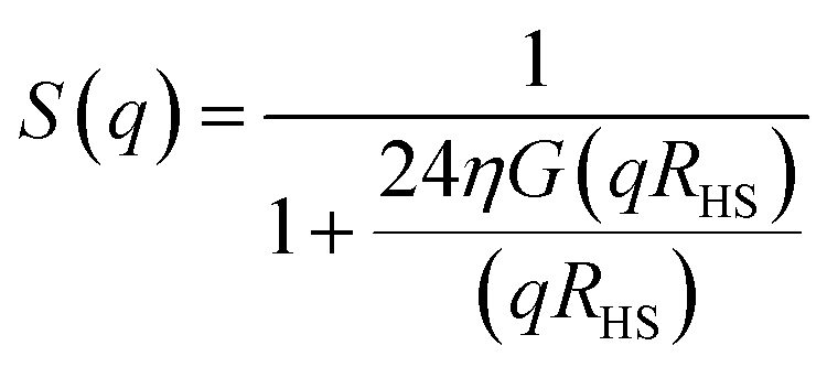
The collected scattering intensities were radially averaged using the IRENA macros39 for Igor Pro (Wavemetrics, Portland, USA). The scattering vector q was calculated as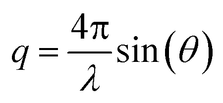 , with λ being the X-ray wavelength and θ half of the scattering angle. In case of ASAXS measurements, the intensities were normalized to the dominant Au scattering peak of the gold matrix (0.01 Å−1). The contribution of the cerium oxide nanoparticles was obtained by subtracting the normalized intensities at the cerium M-edge (905–870 eV), as depicted in the ESI Fig. S2.† A generalized Indirect Fourier Transform (IFT)40,41 was used to evaluate the small angle scattering data. SAXS intensities were analyzed in the q-range between 0.006 Å−1 and 0.04 Å−1 and the ASAXS intensities between 0.02 Å−1 and 0.04 Å−1. To obtain structural information, the 3D structure of the np-Au was modeled as an ensemble of particles. To be able to describe the ligament structure as series of these particles, a Hard-Sphere-Potential (HSP)42,43 was introduced as structure factor S(q):
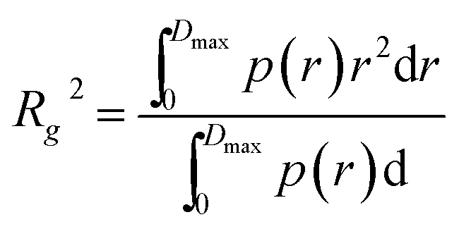
where η is the volume fraction, and RHS is the effective hard-sphere radius. The detailed expression of the function G(qRHS) was described by Pedersen.42 The result of the IFT is the pair-distance-distribution function p(r), which describes the occurrence of distances between pairs of points in real space. Details on the particle shape and mean size can be extracted from the p(r) function of the obtained model. The radius of gyration (Rg) yields information on the spatial extension without assuming a particle shapes:
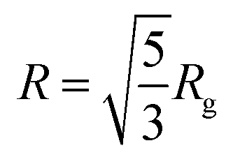
In the case of spherical particles, the particle radius R can be calculated as:
 .44
.44
3. Results and discussion
3.1 Nanoporous gold
Nanoporous gold (np-Au) catalysts show exceptional activity at low temperature applications,1,2 but are known to be susceptible to coarsening at temperatures above 100 °C.7–11 To analyze such structural transitions with soft X-ray SAXS, the np-Au samples were investigated before and after annealing at 520 °C (Fig. 1(a) and (b)). The SAXS signal was measured in the range from 0.006 Å−1 to 0.04 Å− 1 which is sensitive to structure sizes between 150 Å and 1050 Å. Before annealing, the most prominent feature in the scattering curves is a maximum at around 0.01 Å−1 which evolves into a Porod decay towards higher scattering angles (Fig. 1(a)). A heat treatment leads to a decrease in intensity and a shift of this peak to lower q-values indicating a coarsening of the catalyst material (Fig. 1(b)).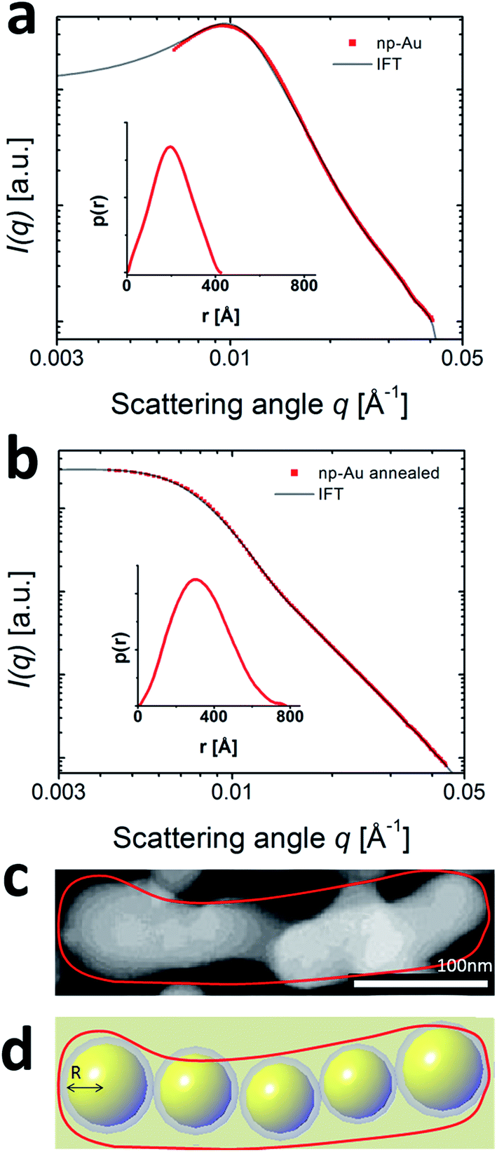 | ||
| Fig. 1 SAXS data of a pure np-Au sample (red dots) as prepared (a) and after (b) annealing at 520 °C. Both measurements were conducted at a photon energy of 905 eV. A generalized indirect Fourier transform yields the corresponding p(r) function. After annealing the peak at 0.01 Å−1 is shifted to lower q-values, which is in accordance with increasing size of the particles representing the ligament structure as indicated in (c) and (d). (c) Scanning Transmission Electron Microscopy of High Angle Annular Dark Field (STEM-HAADF) image of a np-Au, the scale bar has a length of 100 nm. (d) Schematic representation of the model containing chains of particles to approximate the realistic 3D ligament structure of the np-Au sample. | ||
As a direct inversion of the SAXS data into real space is impossible due to the missing phase information, the established method is to develop a model of the investigated material with a set of variable parameters which are adjusted to fit the experimental data. Such a model allows to draw more detailed, quantitative conclusions even about complex materials.45,46 In Fig. 1(c), a typical ligament of a np-Au sample is shown. The visual impression of the gold network suggests to model the ligament network as chain of interconnected particles, like presented in Fig. 1(d). The averaged diameter of the np-Au was analyzed in detail by Shi et al.15 and sizes in the order of 40 nm are reported, a size range covered by the q-range of the SAXS signal.
The experimental scattering data was modeled as a virtual particle ensemble by using the generalized Indirect Fourier Transform (IFT) method described by Glatter.41,47 The IFT analysis provides a distance distribution function p(r) with real space information on structure and size of the particle ensemble. The proximity of the virtual particles in the catalyst ligament creates additional forward scattering much alike a high concentration particle solution. This interaction can be considered by a hard-sphere potential addition to the IFT as described by Pedersen.42 The model yields a comprehensive information about the catalyst: first, the distance distribution function p(r), which allows to conclude on the shape of the virtual particles forming the catalyst and to obtain their radius of gyration (Rg). Second, the hard sphere interaction radius of the virtual nanoparticles in the gold ligament. The HSR describes the distance of the individual gold nanoparticles inside the catalyst ligament (ESI Fig. S5†). Third, we obtain the volume fraction (VF) of the gold nanoparticles of a specific size inside the scattering volume. All quantities were obtained by iterative optimization until the model was a sufficient representation of the scattering data.
The results of modeling the SAXS curves of the np-Au catalyst before and after annealing at 520 °C are shown in Fig. 1. The red dots show the experimental data, while the solid lines in panels Fig. 1(a) and (b) display the modeled data. From the shape of the distance distribution function p(r) we conclude48 that the geometry of the virtual particles is most suitably represented as spherical building blocks that form the ligaments. For spherical particles, the radius of gyration can be converted to an average radius (R) of the particle ensemble: 204 Å before and 332 Å after heating (Table 1). As shown in the size distribution graph in Fig. 1(a) and (b), the distribution of particle sizes became broader after annealing. Both effects can be interpreted as a coarsening of the material, i.e. an increase in the average ligament diameter and in polydispersity of the gold ligaments.
| Nanoporous catalyst sample | Rg [Å] | R [Å] | Volume fraction (VF) | Fig. |
|---|---|---|---|---|
| Au | 158.1 ± 0.5 | 204.1 ± 0.1 | 0.225 ± 0.3 | 1(a) |
| Au, annealed at 520 °C | 256 ± 0.8 | 331.6 ± 0.1 | 0.08 ± 0.3 | 1(b) |
| Au + CeO2 | 155.4 ± 0.7 | 200.6 ± 0.1 | 0.265 ± 0.05 | 2(a) |
| Au + CeO2 annealed at 520 °C | 159.4 ± 0.8 | 205.2 ± 0.1 | 0.225 ± 0.3 | 2(b) |
| Only CeO2 | 78.7 ± 5.7 | 101.6 ± 0.9 | 0.3 ± 0.4 | 3(a) |
| Only CeO2, annealed at 520 °C | 78.7 ± 1.8 | 101.6 ± 0.2 | 0.17 ± 0.2 | 3(b) |
Our model indicates that the volume fraction of the np-Au in the above determined size range decreased from 0.225 to 0.08. To understand this drastic decrease, it is important to be reminded that the size range in which our experiment is sensitive ranges from 150 Å to 1050 Å. This implies, that structures with a radius larger than 1050 Å cannot be detected and appear as a virtual loss of material. Hence the decrease in volume contribution of the particle ensemble from 0.225 to 0.08 points to a loss of structures in the detectable size range due to coarsening of the pure np-Au material. This interpretation would be in line with the general notion that a coarsening of the gold structure occurs and the average radius of the remaining scatterers increased by ≈60% from 204 Å to 332 Å (which would correspond to a ligament diameter increase from 40 nm to 66 nm). The obtained values for the diameter of the gold ligaments matches very well with the SEM data from literature15 discussed above.
3.2 Nanoporous gold with CeO2 deposits
In previous studies, it was found that ceria particles deposited on the np-Au surface are capable to stabilize the np-Au ligaments at higher temperatures and the interface between np-Au and CeO2 was found to be crucial leading to enhanced catalytic activity.13 Since the melting point of CeO2 is 2400 °C, the Huttig-temperature needed for surface recrystallization and coarsening is about 630 °C.15 The CeO2/np-Au sample was studied by SAXS at an energy of 905 eV, just above the cerium absorption edge, before and after annealing at 520 °C, which is represented in Fig. 2. The same IFT analysis as for the pure np-Au sample described above was applied (Fig. 1 and 2) and the addition of CeO2 did not impact the position of the Au scattering peak (ESI Fig. S3†).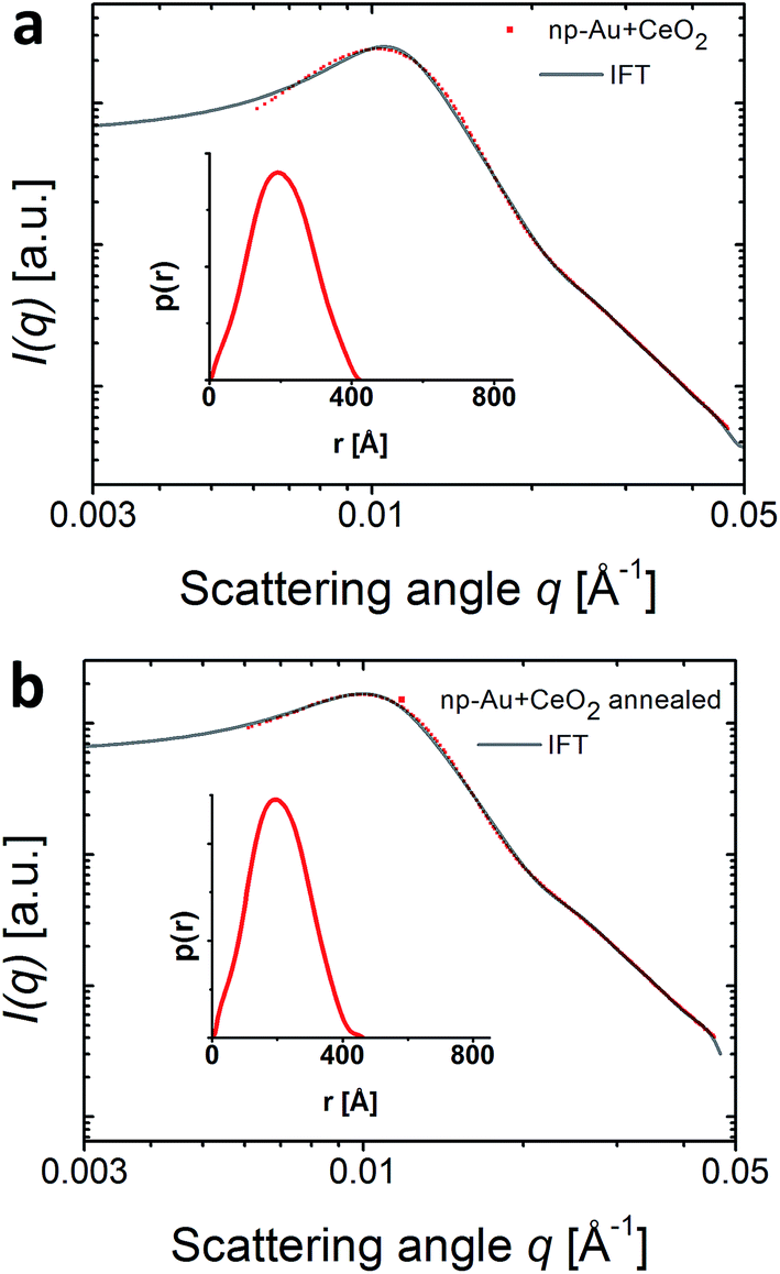 | ||
| Fig. 2 SAXS data of the CeO2/np-Au sample (a) before and (b) after annealing at 520 °C. Both measurements were conducted at a photon energy of 905 eV. The measured data are displayed as red dots and a fit using a generalized IFT as a line. An inset shows the resulting p(r) function which reveals a spherical shape. The comparison of (a) and (b) furthermore depicts that the annealing did not alter the morphology of the catalyst. | ||
As it was shown by Shi et al.15 on the same sample system, the annealing did not lead to a coarsening of the catalyst, revealing the stabilizing effect of the ceria. Moreover, it was shown in SEM measurements that the averaged ligament size of np-Au is in the order of 40 nm.15 Further analysis by TEM and EDX reveal a porous np-Au substrate covered by CeO2 deposits.15,16 In our SAXS experiment, the scattering peak remained at the same position and the p(r) function shows that both, size and shape of the gold ligaments remained constant. Using the spherical shape of the p(r) function, the average radius R of the particles forming the model ligament did not change (200 Å before and 205 Å after annealing, Table 1). Thus, SAXS indicates that the average ligament diameter remains at ≈40 nm.
3.3 ASAXS analysis of CeO2/np-Au
The deposition of ceria particles on the np-Au was found to stabilize the np-Au ligaments during thermal annealing as it is obvious from the SAXS data presented in Fig. 2. However, the question whether the CeO2 nanoparticles present as deposits on the nanoporous gold are changed during thermal treatment remains. Previous reports on the annealing of TiO2/np-Au showed a strong dependence of the catalytic activity on the thermal treatment and a fast decrease in activity with the onset of oxide particle growth.14 ASAXS offers the unique possibility to address single elements by comparing measurements before and in resonance with the absorption edges of metals, i.e. at two different photon energies at which the scattering cross section is selectively altered for a specific element.The ASAXS data were recorded at E1 = 905 eV and E2 = 870 eV, i.e. above and below the cerium M-edge (ESI Fig. S1†). After subtraction of the scattering curves (I(E1) − I(E2)), the sole contribution of the CeO2 nanoparticles was obtained which is depicted in Fig. 3. The scattering curves were normalized on the dominating Au scattering (ESI Fig. S2†). While the shape of the dominating Au scattering was identical, a difference was found at higher q-values. This scattering contribution corresponds solely to the ceria nanoparticles which are of smaller size than the np-Au structures. As it is represented in Fig. 3(a) and (b), the differential ASAXS scattering curve exhibits two shoulders at 0.021 Å−1 and 0.04 Å−1 which are less pronounced after annealing (Fig. 3(b)).
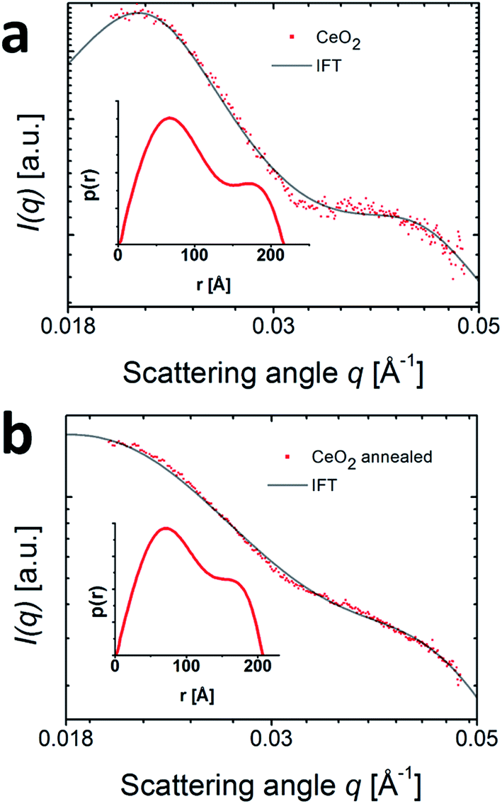 | ||
| Fig. 3 The ASAXS data of CeO2 nanoparticles (dots) was obtained after subtraction of scattering curves measured above and below the cerium M-edge (E1 = 905 eV and E2 = 870 eV). The data was measured (a) before and (b) after annealing. Modeling was performed using an indirect Fourier transform with a hard sphere interaction potential (line). The inset depicts the p(r) function which shows a bimodal distribution with two average radii at 70 Å and 170 Å. | ||
To model these CeO2 nanoparticles we used generalized IFT with a hard-sphere interaction potential as described above for the np-Au SAXS data. The p(r) functions show bimodal distributions and the two average radii of gyration of the bimodal distribution are 70 Å−1 and 170 Å−1. The corresponding radii amount to 90.3 Å−1 and 219.4 Å−1. This results is in agreement with the studies performed by Shi et al.15 on the same sample system where the size of CeO2 was in most cases around 10–20 nm and sometimes up to 30 nm.15,16 After annealing, the bimodal distribution of the p(r) function is retained, as shown in Fig. 3(b), indicating no change in the CeO2 particle sizes. However, the VF of the CeO2 particles decreased from 0.3 to 0.17 which could be caused by an alloying of CeO2 with the gold phase. During the alloying the distinct sizes of the CeO2 particles would vanish and become invisible for SAXS, thus resulting in a lower VF. An alternative interpretation would be a coalescence of CeO2 into structures so large that the scattering signal is in a q range below the detected one. The absence of such structures in recent electron microscopy images (Baier et al.30 and Shi et al.15) favor the first model.
4. Summary and conclusion
In this study, SAXS and ASAXS were used to determine the sizes of np-Au and CeO2/np-Au before and after annealing. The average radius of nanoparticles used for modeling the np-Au ligaments was quantified by SAXS as 200 Å before the annealing treatment. After annealing, the size of pure np-Au increased to a radius of 330 Å. It was shown that the deposition of CeO2 nanoparticles successfully prevented the sample from coarsening, represented by the average size of the np-Au which remained at radius ∼200 Å. With ASAXS it was possible to extract the size of the deposited CeO2 nanoparticles as a bimodal distribution around 70 Å and 170 Å radius of gyration, which did not change after annealing. Therefore, it can be concluded that the ceria particles are not influenced by the annealing process and at the same time stabilize the np-Au framework.The beauty of the application of SAXS and ASAXS to catalyst material is that the result is averaged across a large catalyst area and is able to access 3D structures even under in-operando conditions. At modern synchrotron sources the photon energy can be easily adjusted which is extremely valuable for ASAXS. The soft X-ray regime does not only allow to cover the M-edges of most relevant metals, but also to use a large variety of complementary methods like NEXAFS, X-ray fluorescence and resonant imaging techniques.49 While the sensitivity in the soft X-ray range was proven to be very high, the experiments need to be done in vacuum, which complicates the experimental setup. Despite the high level of experimental complexity, the application of ASAXS in the soft X-ray regime was shown to be a powerful tool to study the morphology of catalysts and nanomaterials such as to investigate two phase systems like finely dispersed particles in a matrix. This allows further estimating the Au/ceria interface in the future under in-operando conditions and thus to correlate it directly to the catalytic performance of this inverse Au/CeO2 catalyst system.
Conflicts of interest
There are no conflicts of interest to declare.Acknowledgements
We acknowledge the virtual institute VI 403 “In situ Nano Imaging of Biological and Chemical Processes” of the Helmholtz Society, the BMBF project 05K16PC1, the BMBF projects “X-ray microscopy” (05K10VK1) and “Nanoscopy” (05K13VK2), the Cluster of Excellence RESOLV (EXC 1069), and the Helmholtz Research Program “Science and Technology of Nanosystems” (STN) for financial support. S. B. was supported by a PhD grant from “Stiftung der Deutschen Wirtschaft”. Furthermore, we acknowledge the BESSY staff for their experimental support.References
- V. Zielasek, B. Jürgens, C. Schulz, J. Biener, M. Biener, A. Hamza and M. Bäumer, Angew. Chem., Int. Ed., 2006, 45, 8241–8244 CrossRef CAS PubMed
.
- A. Wittstock, J. Biener and M. Bäumer, Phys. Chem. Chem. Phys., 2010, 12, 12919–12930 RSC
- L. Y. Chen, X. Y. Lang, T. Fujita and M. W. Chen, Scr. Mater., 2011, 65, 17–20 CrossRef CAS
- C. A. R. Chapman, H. Chen, M. Stamou, J. Biener, M. M. Biener, P. J. Lein and E. Seker, ACS Appl. Mater. Interfaces, 2015, 7, 7093–7100 CAS
- T. Fujita, P. Guan, K. McKenna, X. Lang, A. Hirata, L. Zhang, T. Tokunaga, S. Arai, Y. Yamamoto, N. Tanaka, Y. Ishikawa, N. Asao, Y. Yamamoto, J. Erlebacher and M. Chen, Nat. Mater., 2012, 11, 775–780 CrossRef CAS PubMed
- J. A. Rodriguez, S. Ma, P. Liu, J. Hrbek, J. Evans and M. Pérez, Science, 2007, 318, 1757–1760 CrossRef CAS PubMed
- A. Y. Chen, S. S. Shi, F. Liu, Y. Wang, X. Li, J. F. Gu and X. F. Xie, Appl. Surf. Sci., 2015, 355, 133–138 CrossRef CAS
- M. J. Matthews, Nanoscale, 2016, 8, 785–795 RSC
- Y. C. K. Chen-Wiegart, S. Wang, Y. S. Chu, W. Liu, I. McNulty, P. W. Voorhees and D. C. Dunand, Acta Mater., 2012, 60, 4972–4981 CrossRef CAS
- Y. L. Zhengmin, Z. Shuping, L. Hongtao, S. Weijiang and Y. Ding, J. Nanosci. Nanotechnol., 2009, 9, 1651–1654 CrossRef
- J. Biener, A. Wittstock, M. M. Biener, T. Nowitzki, V. A. Hamza and M. Baeumer, Langmuir, 2010, 26, 13736–13740 CrossRef CAS PubMed
- M. M. Biener, J. Biener, A. Wichmann, A. Wittstock, T. F. Baumann, B. Marcus and A. V. Hamza, Nano Lett., 2011, 11, 3085–3090 CrossRef CAS PubMed
- A. Wichmann, A. Wittstock, K. Frank, M. M. Biener, B. Neumann, L. Mädler, J. Biener, A. Rosenauer and M. Bäumer, ChemCatChem, 2013, 5, 2037–2043 CrossRef CAS
- M. Bagge-Hansen, A. Wichmann, A. Wittstock, J. R. I. Lee, J. Ye, T. M. Willey, J. D. Kuntz, T. V. Buuren, J. Biener, M. Bäumer and M. M. Biener, J. Phys. Chem. C, 2014, 118, 4078–4084 CAS
- J. Shi, A. Schaefer, A. Wichmann, M. M. Murshed, T. M. Gesing, A. Wittstock and M. Bäumer, J. Phys. Chem. C, 2014, 118, 29270–29277 CAS
- J. Shi, C. Mahr, M. M. Murshed, V. Zielasek, A. Rosenauer, T. M. Gesing, M. Bäumer and A. Wittstock, Catal. Sci. Technol., 2016, 6, 5311–5319 CAS
- S. Baier, C. D. Damsgaard, M. Scholz, F. Benzi, A. Rochet, R. Hoppe, T. Scherer, J. Shi, A. Wittstock, B. Weinhausen, J. B. Wagner, C. G. Schroer and J. D. Grunwaldt, Microsc. Microanal., 2016, 22, 178–188 CrossRef CAS PubMed
- R. Besnard, G. Arrachart, J. Cambedouzou and S. Pellet-Rostaing, RSC Adv., 2015, 5, 57521–57531 RSC
- D. I. Svergun and M. H. J. Koch, Rep. Prog. Phys., 2003, 66, 1735–1782 CrossRef CAS
- B. N. Chaudhuri, Protein Sci., 2015, 24, 267–276 CrossRef CAS PubMed
- C. Conceição, M. Antoniassi, W. Geraldelli and M. E. Poletti, Radiat. Phys. Chem., 2014, 95, 313–316 CrossRef
- T. Gorniak, T. Haraszti, V. M. Garamus, A. R. Buck, T. Senkbeil, M. Priebe, A. Hedberg-Buenz, D. Khoen, T. Salditt, M. Grunze, M. G. Anderson and A. Rosenhahn, PLoS One, 2014, 9(3), e90884 Search PubMed
- A. Von Gundlach, V. M. Garamus, T. Gorniak, H. A. Davies, M. Reischl, R. Mikut, K. Hilpert and A. Rosenhahn, Biochim. Biophys. Acta, Biomembr., 2015, 1858, 918–925 CrossRef PubMed
- M. Gazzano, C. Gualandi, A. Zucchelli, T. Sui, A. M. Korsunsky, C. Reinhard and M. L. Ocarete, Polymer, 2015, 63, 154–163 CrossRef CAS
- N. Naudon, in Modern Aspects of Small-Angle Scattering, Springer Science & Business Media, 1995, pp. 203–219 Search PubMed
- A. Benedetti, L. Bertoldo, P. Canton, G. Goerigi, F. Pinna, P. Riello and S. Polizzi, Catal. Today, 1999, 49, 485–489 CrossRef CAS
- Z. Y. Zhou, Z. Tian, Z. Z. Huang, D. J. Chen and S. Sun, Faraday Discuss., 2008, 140, 81–92 RSC
- T. Gorniak and A. Rosenhahn, Z. Phys. Chem., 2014, 228, 1–16 CrossRef
- A. Wittstock, B. Neumann, A. Schaefer, K. Dumbuya, C. Kübel, M. M. Biener, V. Zielasek, H. P. Steinru, J. M. Gottfried, J. Biener, A. Hamza and M. Bäumer, J. Phys. Chem. C, 2009, 113(14), 5593–5600 CAS
- S. Baier, A. Wittstock, C. D. Damsgaard, A. Diaz, J. Reinhardt, F. Benzi, J. Shi, T. Scherer, D. Wang, C. Kübel, C. G. Schroer and J. D. Grunwaldt, RSC Adv., 2016, 6, 83031–83043 RSC
- T. Kachel, Journal of large-scale research facilities, 2016, 2, A72 CrossRef
- R. Barth, F. Staier, T. Simpson, S. Mittler, S. Eisebitt, M. Grunze and A. Rosenhahn, J. Biotechnol., 2010, 149, 238–242 CrossRef CAS PubMed
- S. Eisebitt, M. Grunze, A. Rosenhahn, R. Barth, F. Staier, T. Simpson and S. Mittler, J. Opt. Soc. Am. A, 2008, 25, 416–422 CrossRef
- T. Gorniak, R. Heine, P. Mancuso, F. Staier, C. Christophis, M. E. Pettitt, A. Sakdinawat, R. Treusch, N. Guerassimova, J. Feldhaus, C. Gutt, G. Grübel, S. Eisebitt, A. Beyer, A. Gölzhäuser, E. Weckert, M. Grunze, I. Vartanyants and A. Rosenhahn, Opt. Express, 2011, 19, 11059–11070 CrossRef CAS PubMed
- R. Heine, T. Gorniak, T. Nisius, C. Christophis, M. E. Pettite, F. Staier, T. Wilhein, S. Rehbein, M. Grunze and A. Rosenhahn, Ultramicroscopy, 2011, 111, 1131–1136 CrossRef CAS PubMed
- K. Giewekemeyer, M. Beckers, T. Gorniak, M. Grunze, T. Salditt and A. Rosenhahn, Opt. Express, 2011, 19, 1037–1050 CrossRef CAS PubMed
- M. Rose, P. Skopintsev, D. Dzhigaev, O. Gorobtsov, T. Senkbeil, A. Von Gundlach, T. Gorniak, A. Shabalin, J. Viefhaus, A. Rosenhahn and I. Vartanyants, J. Synchrotron Radiat., 2015, 22, 819–827 CrossRef CAS PubMed
- A. P. Mancuso, T. Gorniak, F. Staier, O. J. Yefanov, R. Barth, C. Christophis, B. Reime, J. Gulden, A. Singer, M. E. Pettit, T. Nisius, T. Wilhein, C. Gutt, G. Grübel, N. Guerassimova, R. Treusch, J. Feldhaus, S. Eisebitt, E. Weckert, M. Grunze, A. Rosenhahn and I. A. Vartanyants, New J. Phys., 2010, 12, 035003 CrossRef
- J. Ilavsky and P. R. Jemian, J. Appl. Crystallogr., 2009, 42, 347–353 CrossRef CAS
- O. Glatter, J. Appl. Crystallogr., 1977, 10, 415–421 CrossRef
- A. Bergmann, G. Fritz and O. Glatter, J. Appl. Crystallogr., 2000, 33, 1212–1216 CrossRef CAS
- J. S. Pedersen, Adv. Colloid Interface Sci., 1997, 70, 171–210 CrossRef CAS
- D. J. Kinning and L. E. Thomas, Macromolecules, 1984, 17, 1712–1718 CrossRef CAS
- P. Willmot, An Introduction to Synchrotron Radiation, John Wiley & Sons, 2011, vol. 53 Search PubMed
- M. A. Graewert and D. I. Svergun, Curr. Opin. Struct. Biol., 2013, 23, 748–754 CrossRef CAS PubMed
- O. Glatter and O. Kratky, Small angle x-ray scattering, Academic Press, München, 1982 Search PubMed
- O. Glatter, J. Appl. Crystallogr., 1977, 10, 415–421 CrossRef
- D. I. Svergun and M. H. J. Koch, Rep. Prog. Phys., 2003, 66, 1735–1782 CrossRef CAS
- M. Beckers, T. Senkbeil, T. Gorniak, M. Reese, K. Giewekemeyer, S. C. Gleber, T. Salditt and A. Rosenhahn, Phys. Rev. Lett., 2011, 107, 1–4 CrossRef PubMed
Footnote |
| † Electronic supplementary information (ESI) available. See DOI: 10.1039/c7ra05396g |
| This journal is © The Royal Society of Chemistry 2017 |