
 Open Access Article
 This Open Access Article is licensed under a
 Creative Commons Attribution 3.0 Unported Licence
Comparison of the exergy efficiency of four power generation systems from methane using fuel cells
Zhe Wang *a,
Weiyu Fanb and
Guangqing Zhangc
*a,
Weiyu Fanb and
Guangqing Zhangc
aState Key Laboratory of Advanced Metallurgy, University of Science and Technology Beijing, Beijing 100083, China. E-mail: zhewang@ustb.edu.cn
bState Key Laboratory of Heavy Oil Processing, China University of Petroleum, Qingdao, Shandong 266580, China
cSchool of Mechanical, Materials and Mechatronic Engineering, University of Wollongong, NSW 2522, Australia
First published on 11th August 2017
Abstract
Exergy analyses are carried out on four different solid oxide fuel cell (SOFC) systems using methane as the original fuel, with focus on exergy flows, efficiency and destruction. The four processes are (1) CH4-SOFC, which is a CH4 directly fuelled SOFC system with a CO2 capture unit; (2) CH4-SOFC-CLC, in which the CH4-SOFC system is integrated with chemical looping combustion (CLC); (3) SMR-SOFC, i.e. a SOFC system using H2 (H2-SOFC) generated by steam methane reforming (SMR); (4) MC-SOFC-DCFC, which is a combined system of H2-SOFC and a direct carbon fuel cell (DCFC) where H2 and C are supplied by methane cracking (MC). Generally, the CH4-SOFC and CH4-SOFC-CLC processes which directly use CH4 as the fuel of cells have higher exergy efficiency. MC-SOFC-DCFC reaches an overall exergy efficiency of 71.4%, which is 17% higher than that of SMR-SOFC (54.4%) due to the higher exergy efficiency of MC than SMR. The effects of operating parameters on the performance of CH4-SOFC are also examined in detail. The results of this investigation demonstrate that the development of methane directly fuelled SOFC, decreasing its operating temperature and suitable capture of CO2 are the key technologies to improve the energy conversion efficiency of methane fuelled SOFC systems.
1. Introduction
Solid oxide fuel cells (SOFCs) attract considerable interest due to their numerous advantages, in which O2− anions are the species transported through the solid-state electrolyte (commonly yttria-stabilized zirconia (YSZ)). This allows SOFCs to operate, in principle, on any combustible fuels.1 The use of YSZ electrolyte requires SOFCs to be operated at high temperatures (700–1000 °C) which make SOFCs very suitable for coupling with gas turbines (GTs) or steam methane reforming (SMR).1,2 The intermediate temperature solid oxide fuel cells (IT-SOFCs) with an operating temperature 500–600 °C have been developed by replacing the commonly used YSZ electrolyte with a cerium gadolinium oxide (CGO) or lanthanum strontium gallate magnesite (LSGM) electrolyte.3 The lower operating temperature can reduce cost and start-up time of a system.Still, so far, hydrogen is the predominant fuel for fuel cell applications. Approximate 75% of the global hydrogen production currently is achieved by SMR, which a multi-stage process. The overall SMR reaction is given in reaction (1).
| CH4(g) + 2H2O(g) = CO2(g) + 4H2(g), ΔH298 K = 164.7 kJ | (1) |
Since the reaction is highly endothermic, huge amounts of supplemental energy is required to maintain the reforming temperature. The energy is usually provided by the combustion of additional methane (if necessary) or the off-gas from the H2 purification unit, which resulting in high CO2 emissions and a relatively low energy efficiency of SMR (60–75%).4,5
Nowadays, it has been increasingly necessary to investigate and develop low CO2 emission technologies owing to the greenhouse gas (GHG) concerns. In comparison with SMR, methane cracking (MC), as described by reaction (2), is a new alternative to hydrogen production due to its simplicity of process and the absence of COx by-product.6
| CH4(g) = C(s) + 2H2(g), ΔH298 K = 74.6 kJ | (2) |
When the temperature is higher than 600 °C, the methane cracking reaction can occur at a reasonable rate. As the only gaseous product, hydrogen can be easily separated from the unreacted methane via membrane or adsorption separation, which is much simpler compared to the complex purification processes that also deal with CO2 and CO in SMR. The produced solid carbon has value as a replacement for carbon black or can serve as the fuel of a direct carbon fuel cell (DCFC).7,8 Liu et al.8 proposed an energy conversion system on the basis of a MC reactor together with two fuel cells. In this model, the hydrogen-rich product of MC was used in an internal reforming solid oxide fuel cell (IRSOFC) and the carbon generated via MC was fed into a DCFC. An exergy efficiency of 68.2% was proposed in that system. Previously, we conducted detailed comparative exergy analysis of three MC processes with different CO2 capture methods. It is demonstrated that these MC processes can achieve global exergy efficiencies close to 90%.9
The application of CO2 capture and storage (CCS) techniques is another promising option of reducing CO2 emissions, which includes pre-combustion capture, post-combustion capture and capture in oxy-combustion.10 Unfortunately all these methods require expensive and complicated equipment and have low energy efficiency due to the high energy penalty. As an attractive technology, the chemical looping combustion (CLC) process emerges which is capable of obtaining inherent separation of CO2.11 In CLC, the fuel combustion is divided into two sub-reactions tanking place in two separate reactors, i.e., a fuel reactor (FR) and an air reactor (AR). A metal oxide as oxygen carriers (OCs) is circled in CLC to oxidise fuel in FR and to be reoxidised in AR by fresh air. The off-gas from FR mainly contains CO2 and water vapour. After water vapour condensation, a highly concentrated CO2 stream ready for transport and storage is obtained. More detailed process description of CLC can be found elsewhere.12,13
Originally, the CLC was proposed to combine with gas turbines for electricity production.11,14,15 Later, proposals on the application of CLC for H2 production have been expanded significantly over the last 10 years, e.g. SMR integrated with CLC (SMR-CLC),5,16–18 auto-thermal chemical-looping reforming (CLR)19,20 and MC integrated with CLC (MC-CLC).9 Chen et al.21 recently incorporated a coal gasification process with SOFC and CLC. The predicted plant net power efficiency is about 49.8% with complete CO2 separation. The thermodynamics of CLC-GT,11,14,15 SMR-CLC16,17 and CLR19,20 have been intensively studied. Nevertheless, investigations on process simulation and thermodynamics of the processes of the SOFC integrated with CLC and the MC integrated with fuel cells are limited.21
The objective of this paper is, by means of energy and exergy analyses, to evaluate and compare four different fuel cell processes which use methane as the original fuel, including (1) CH4-SOFC, i.e. CH4 directly fuelled SOFC with a CO2 capture unit; (2) CH4-SOFC-CLC, i.e. CH4 directly fuelled SOFC integrated with CLC; (3) SMR-SOFC, i.e. SOFC using H2 (H2-SOFC) generated by SMR; (4) MC-SOFC-DCFC, i.e. H2-SOFC coupled with DCFC, with H2 and C supplied by MC. The simplified schematics of the four fuel cell processes are described in Fig. 1. A systematic comparison of the four model processes is helpful for the selection and development of the most efficient methane (natural gas) conversion technologies.
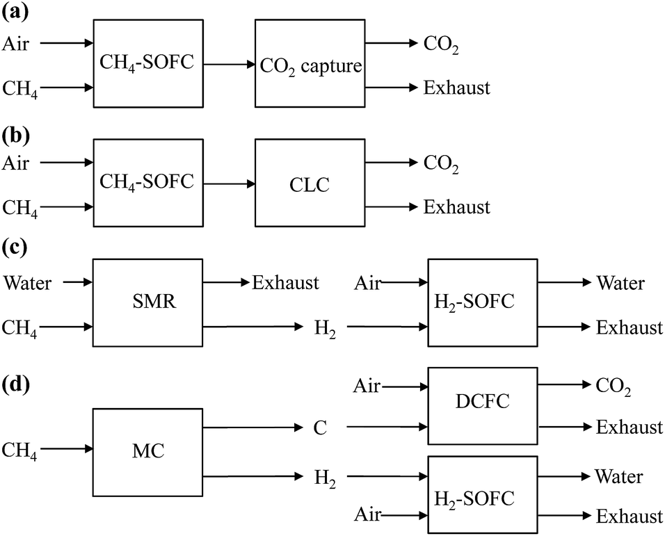 | ||
| Fig. 1 Simplified schematics of fuel cell systems for power generation from methane. (a) CH4-SOFC, (b) CH4-SOFC-CLC, (c) SMR-SOFC, (d) MC-SOFC-DCFC. | ||
2. Methodology
2.1 Model description of SOFCs
The SMR, MC and DCFC processes considered in this study are taken from the models reported in the literature. This section describes the detailed models of CH4-SOFC, CH4-SOFC-CLC and H2-SOFC.Some of the SOFC models reported in the literature consider the effect of different forms of over potential on the SOFC performance, which are mainly caused by the electrochemical reaction activation, ohmic resistance and concentration depletion.2,8,22,23 The values of the over potential are determined by many factors such as temperature, material of electrolyte, and the material, size and even morphology of electrodes. When methane is directly fed into the anode chamber, steam reforming reaction takes place inside the chamber and the anode reaction is still the oxidation of hydrogen. In spite of the difference in fuels fed, all four SOFCs involve hydrogen oxidation reaction. The over potential of the oxygen reduction reaction is also common to all four SOFCs. So the over potential issues equally affect all of the four SOFCs. In this study, the ideal fuel cell model is taken and the energy loss due to over potential is neglected, which does not affect the conclusions in comparing the performance of four SOFCs.
The key components of the CH4-SOFC process developed in this investigation are a chemical equilibrium SOFC, a post-burner (PB), a heat exchanger (HE), a gas turbine (GT), a condenser, an air compressor (AC), a fuel compressor (FC) and a CO2 capture unit. The detailed schematic of the system is shown in Fig. 2.
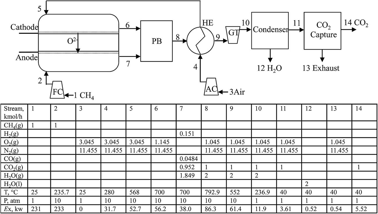 | ||
| Fig. 2 The schematic of the CH4-SOFC process. | ||
In the SOFC under operation, the molecular oxygen from preheated air (node 5) is reduced to oxygen anions at the cathode by gaining electrons supplied from an external circuit. Driven by the difference in oxygen chemical potential between the anode and cathode compartments, oxygen anions migrate through the solid electrolyte to the anode where they are consumed by oxidation of the compressed CH4 by FC. The electrons released from the electrochemical reaction flow through an external circuit to the cathode to complete the circuit. The lean fuel (node 7) and lean air (node 6) exit the cell at the operating pressure and temperature of SOFC. The CO, H2 and unreacted CH4 in the lean fuel are mixed with the lean air and combusted in the PB. The high-temperature flue gas from the combustor is used to preheat the air, compressed by AC, to keep the operating temperature of the SOFC. The exhaust stream (node 9) from the HE then drives the GT to produce electricity and is cooled to 40 °C through the condenser. The remaining gas (mostly N2, CO2 and O2) is then directed into a CO2 capture unit. In this study, consumption of 3.95 MJ kg−1 CO2 of heat at 220 °C and 0.32 MJ kg−1 CO2 of work is assumed in the CO2 capture unit by MEA scrubbing.24
Fig. 3 shows a detailed schematic of the CH4-SOFC-CLC process. The main difference between it and CH4-SOFC depicted in Fig. 2 is that the PB where the direct combustion of lean fuel occurs in CH4-SOFC is replaced by a CLC unit. NiO/Ni is used as the solid oxygen-carrier of the CLC in this model. Also, two heat exchangers (HE1 and HE2) and gas turbines (GT1 and GT2) are utilized to preheat the fresh air and recover as much heat as possible from the flue gas exiting the CLC.
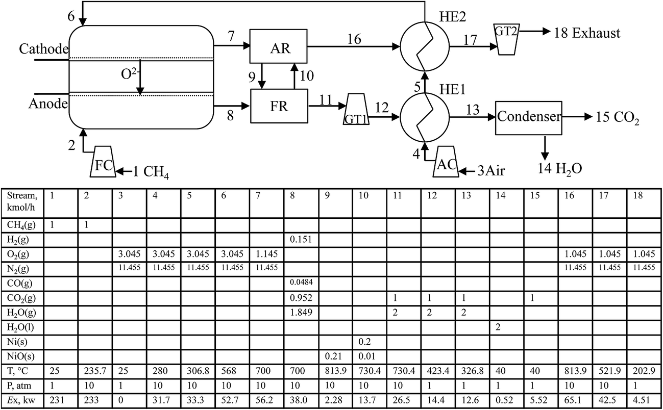 | ||
| Fig. 3 The schematic of the CH4-SOFC-CLC process. | ||
The lean fuel (node 8) in this model flows into the FR and is oxidised by the NiO (node 9). The products include gas stream (node 11) containing CO2 and steam, and solid stream (node 10) containing Ni and a few unreacted NiO. All the solids are sent to the AR. The flue gas exiting the FR firstly drives the GT1 and then is cooled by HE1. After water condensation, an almost pure CO2 stream obtained. The heat released from the oxidation of Ni by air in AR increases the temperatures of the NiO solid and the lean air (node 16). The lean air firstly preheats the fresh air to the required temperature and then drives the GT2 to produce electricity.
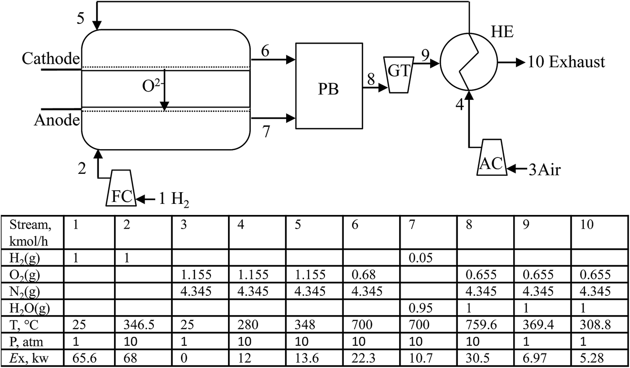
The detailed schematic of the H2-SOFC process is shown in Fig. 4. As H2-SOFC is fuelled by H2, the exhaust (node 10) exiting the process mainly consists of water and lean air, therefore a CO2 capture unit is not required in this model. In comparison with CH4-SOFC (Fig. 2), another difference is that the high-temperature exhaust (node 8) from the PB firstly drives a GT and then preheats the compressed air. By this arrangement, not only the compressed air is preheated to a required temperature to maintain the operating temperature of the cell, but also the exhaust gas can be used to drive a GT to produce more electricity. In comparison, the CH4-SOFC process needs to use the exhaust (node 8) from the PB to firstly preheat the compressed air (node 5), as the cell in CH4-SOFC has a higher capability of producing electricity than that in H2-SOFC and the compressed air (node 5) requires to be preheated to a higher temperature to keep the operating temperature of the cell.
 | ||
| Fig. 4 The schematic of the H2-SOFC process. | ||
The maximum electrical power available from a fuel cell is determined by the Gibbs free energy difference across the electrolyte membrane, ΔG. It determines the electromotive force (EMF) of the cell, E, through the Nernst equation. The main chemical reactions involved in CH4-SOFC are shown below, and only hydrogen combustion reaction (reaction (5)) occurs in H2-SOFC.
| CH4 + ½O2 = CO + 2H2, ΔH = −35.6 kJ | (3) |
| CO + ½O2 = CO2, ΔH = −283 kJ | (4) |
| H2 + ½O2 = H2O, ΔH = −241.8 kJ | (5) |
Above reactions (3)–(5) consist of half cell reactions:
| ½O2 + 2e− = O2− | (6) |
| F + O2− = FO + 2e− | (7) |
| F + ½O2 = FO | (8) |
Combining reactions (7) and (8), the following reaction is obtained:
| O2− = ½O2 + 2e− | (9) |
Reactions (6) and (9) consist of a concentration cell, of which the EMF is25
| E = (RT/4F)ln{P(O2 cathode)/P(O2 anode)} | (10) |
The simulation of the SOFC reactions was carried out by application of Aspen Plus Software using PR-BM method. It used the built-in RGibbs modules, with an approach of Gibbs free energy minimisation. Oxygen, water, hydrogen, carbon dioxide, carbon monoxide, methane as well as pure carbon (by reaction (2)) were added manually as the possible species in CH4-SOFC and CH4-SOFC-CLC. Oxygen, water and hydrogen were chosen as the possible species in the H2-SOFC. It is found that no carbon is formed in the anode part of cells in this study.
The base-case operating parameters of the three SOFC processes are listed in Table 1. Main assumptions are considered including:
| Parameter | Unit | CH4-SOFC | CH4-SOFC-CLC | H2-SOFC |
|---|---|---|---|---|
| a Post-burner, air reactor and fuel reactor are operated adiabatically; the operating temperatures are determined by the heat balance of each device. | ||||
| Fuel cell | ||||
| Fuel type | CH4 | CH4 | H2 | |
| Fuel flow | kmol h−1 | 1 | 1 | 1 |
| Air flow | kmol h−1 | 14.5 | 14.5 | 5.5 |
| Temperature | °C | 700 | 700 | 700 |
| Pressure | atm | 10 | 10 | 10 |
| O2 anode,in/fuel | 1.9 | 1.9 | 0.475 | |
![[thin space (1/6-em)]](https://www.rsc.org/images/entities/char_2009.gif) |
||||
| Post-burnera | ||||
| Pressure | atm | 10 | — | 10 |
|
||||
| Air reactora | ||||
| Pressure | atm | — | 10 | — |
|
||||
| Fuel reactora | ||||
| Pressure | atm | — | 10 | — |
• The pressure and heat losses are ignored in all processes.
• The flow rate of fuel (methane and hydrogen) fed into each cell of three processes is set at 1 kmol h−1. This reference amount for calculation does not affect the calculated efficiency of the processes to be compared.
• Air is assumed to be constituted by 21 vol% O2 and 79 vol% N2.
• AC is assumed to be a three stage compressor. The polytropic and mechanical efficiencies for all turbines and compressors are considered as 0.86 and 0.9, respectively.
• The minimum temperature difference in heat exchangers is considered to be is 20 °C.
2.2 Exergy analysis
The exergy of a substance is evaluated against the environment which is assumed to be at 25 °C and 1 atm in this study. Three forms of exergy transfer are present in a system, namely, work interaction, heat interaction and that occurred due to material streams and detailed calculation methods of the three forms of exergy can be found elsewhere.26 Table 2 lists the standard mole chemical exergy of materials used in this study.26| Substance | Exch, J mol−1 |
|---|---|
| CH4 | 831650 |
| O2 | 3869 |
| N2 | 584 |
| CO | 275100 |
| CO2 | 19870 |
| H2 | 236100 |
| H2O(g) | 9500 |
| H2O(l) | 900 |
| Ni(s) | 232700 |
| NiO(s) | 23000 |
The exergy destruction (Exdest) for a steady-state system is calculated via exergy balance, defined in eqn (11). Exdest measures the unrecoverable lost capability to do work. The lost exergy loss (Exls) is defined in eqn (12) as the sum of Exdest within the system and the exergy ejected (Exej) in the streams which are not utilized. The unutilized streams include streams 12, 13 and 14 in CH4-SOFC, 14, 15 and 18 in CH4-SOFC-CLC, and 10 in H2-SOFC.
| Exdest = Exin − Exout | (11) |
| Exls = Exdest + Exej | (12) |
The overall exergy efficiency of these SOFC processes is defined as the ratio of the produced net power work (Wnet) to the total exergy input to the system, defined in eqn (13). Wnet is the difference between the power generated from the cells and gas turbines and that consumed by the power work consumed by the compressors.
 | (13) |
Exergy analysis also can be used in individual devices. The exergy efficiency (φk) of a device k can be defined in eqn (14).
 | (14) |
For a chemical process such as cells, reactors and post-burners, both physical and chemical exergy are included in the calculation of φk. For pumps and compressors, only the power supplied to the devices is counted in the exergy input while the exergy increase in the stream leaving pumps and compressors is included in the exergy output. For heat exchangers, the reduction of the physical exergy of the hot streams corresponding to their temperature reduction is counted as the exergy input while the increase of the physical exergy of the cold streams corresponding to their temperature increase is considered as the exergy output, because only heat transfer is involved in the energy transformation processes.
3. Results and discussion
3.1 Exergy analysis of CH4-SOFC, CH4-SOFC-CLC and H2-SOFC
All the cells in the three processes are assumed to be operated at 700 °C and 10 atm. In general, the oxygen content in the cathode compartment of a SOFC is lower than 21%. However, if the air amount entering the cathode compartment carries far larger amount of O2 than that passing through the solid electrolyte, assuming a constant partial pressure of O2 (PO2 = 2.1 atm) in the cathode compartment does not cause significant deviation in the calculated power output.The amount of O2 passing through the solid electrolyte of a SOFC for per mole of fuel has a significant impact on the equilibrium composition of the lean fuel in the anode compartment and the corresponding capability of producing electricity of the SOFC. Fig. 5(a) presents the effect of the molar ratio of the oxygen passing through the solid electrolyte to the fuel (CH4) flowing into the anode compartment of the CH4-SOFC (O2 anode,in/CH4) on the equilibrium O2 partial pressure of the lean fuel leaving the anode compartment (P(O2 anode)). When the O2 anode,in/CH4 ratio is below 1.7, increasing the O2 anode,in/CH4 has little effect on the P(O2 anode), and so on EMF of the cell, but results in an increase of the electric charge transferred by the cell, and so the power output increases nearly linearly. As O2 anode,in/CH4 ratio approaches 2, the combustion of CH4 approaches completion. The P(O2 anode) increases sharply, causing the power output reaching a peak at about O2 anode,in/CH4 = 1.9. Beyond this range, the power output sharply decreases due to the decrease of the EMF corresponding to the increase of the oxygen content in the lean fuel. As shown in Fig. 5(b), similar trends are there in the changes of the P(O2 anode) and the power output from a H2-SOFC operated at the same conditions as the CH4-SOFC. The combustion of H2 approaches completion and the P(O2 anode) increases sharply, when the O2 anode,in/H2 approaches 0.5 corresponding to the stoichiometry of reaction (5). The peak power output appears at O2 anode,in/CH4 ratio about 0.475.
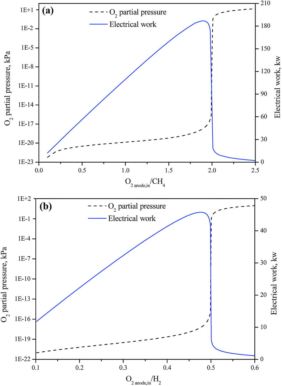 | ||
| Fig. 5 The effect of the molar ratio of O2 and fuel flowing into the anode compartment of SOFC on the equilibrium O2 partial pressure of lean fuel leaving the anode compartment and the electrical power produced by (a) CH4-SOFC and (b) H2-SOFC, both operated at 700 °C and 10 atm and with a constant O2 content at 21% in the cathode compartment. | ||
In this work, the exergy analysis of CH4-SOFC and CH4-SOFC-CLC systems is carried out at O2 anode,in/CH4 = 1.9; while for H2-SOFC system, it is carried out at O2 anode,in/H2 = 0.475.
Table 3 presents the exergy balances and exergy efficiencies of CH4-SOFC, CH4-SOFC-CLC and H2-SOFC operating with the base-case parameters shown in Table 1. For the CH4-SOFC-CLC and H2-SOFC processes, the exergy input is only from the fuel. The CO2 separation unit of the CH4-SOFC process to capture the CO2 generated by the combustion of CH4 brings about extra consumption of exergy, accounting for 9.1% of the total exergy input in the process.
| CH4-SOFC | CH4-SOFC-CLC | H2-SOFC | ||||
|---|---|---|---|---|---|---|
| kW | % | kW | % | kW | % | |
| a Energy consumed by compressors (data in brackets) is considered from expanding gas turbines and so not counted in the exergy input.b Net power output of gas turbines is after subtracting that consumed by compressors.c Exch,CO2 is counted in the Exej and so not repeatedly counted in the exergy output. | ||||||
| Exergy input | 254 | 100 | 231 | 100 | 65.6 | 100 |
| ExCH4 | 231 | 90.9 | 231 | 100 | — | — |
| ExH2 | — | — | — | — | 65.6 | 100 |
| Wcompressorsa | (36.4) | — | (36.4) | — | (15.6) | — |
| ExCO2 capture | 23 | 9.10 | — | — | — | — |
| Exergy output | 197 | 77.5 | 201 | 87.2 | 56.2 | 85.6 |
| Wcell | 183 | 72.1 | 183 | 79.3 | 45.3 | 69.1 |
| W′GTb | 7.06 | 2.78 | 7.61 | 3.3 | 5.59 | 8.53 |
| Exej | 6.58 | 2.59 | 10.6 | 4.57 | 5.28 | 8.05 |
| Exch,CO2c | (5.52) | — | (5.52) | — | — | — |
| Destroyed exergy | 57.2 | 22.5 | 29.6 | 12.8 | 9.42 | 14.4 |
| Lost exergy | 63.8 | 25.1 | 40.2 | 17.4 | 14.7 | 22.4 |
| Exergy efficiency | 74.9 | 82.6 | 77.6 | |||
The exergy output of the three processes is mainly contributed by the power produced by each cell (Wcell); the major lost exergy is the destroyed exergy owing to the irreversibility in the processes. The CH4-SOFC-CLC process obtains the highest exergy efficiency (82.6%), followed by H2-SOFC (77.6%). The lowest exergy efficiency occurs in CH4-SOFC, 74.9%. It is noted that without capturing the CO2 in the flue gas the exergy efficiency of CH4-SOFC can reach 82.4%, which is close to that of CH4-SOFC-CLC. It is also noted that the exergy efficiencies of CH4-SOFC (74.9%) and H2-SOFC (77.6%) are higher than those given in some other thermodynamic SOFC analysis papers, which is reasonable since the ideal fuel cell model is assumed and the exergy destruction due to over potential is neglected in this work. The adoption of gas turbines to recover the pressure energy of the off gases for power generation contributes to the high efficiency of the processes.
Over potential is a common issue related to the characteristics of electrochemical reactions and detailed reaction conditions, such as temperature, the material of electrolyte, the material, size and even morphology of electrodes, the current density on the electrodes for a given electrode reaction, etc. Fig. 6 shows the effect of over potential on the exergy efficiencies of the three SOFC processes. The exergy efficiencies of all of the processes decreased greatly with the increase of over potential. Reducing over potential is one of the key engineering technologies to improve the energy conversion efficiency of SOFC systems.
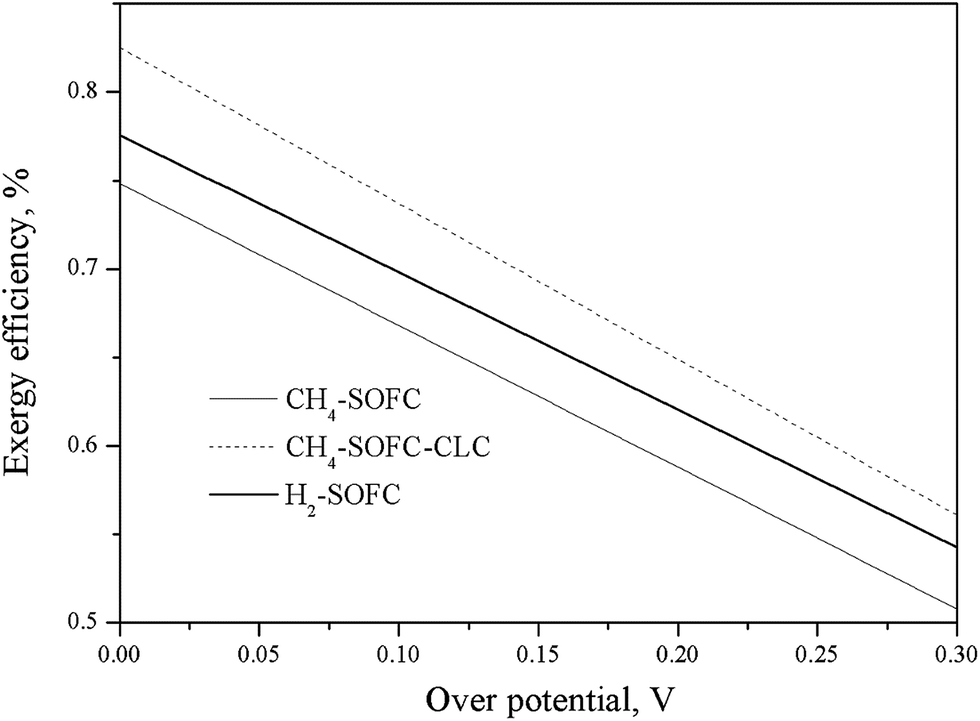 | ||
| Fig. 6 Effect of over potential on the exergy efficiencies of CH4-SOFC, CH4-SOFC-CLC and H2-SOFC. | ||
To further understand the exergy destruction in the three SOFC processes, the exergy analysis of each device in the processes is implemented, and the results are listed in Table 4.
| CH4-SOFC | CH4-SOFC-CLC | H2-SOFC | |||||||
|---|---|---|---|---|---|---|---|---|---|
| Exdest (kW) | % of total Exdest (%) | Device φk (%) | Exdest (kW) | % of total Exdest (%) | Device φk (%) | Exdest (kW) | % of total Exdest (%) | Device φk (%) | |
| Cell | 8.47 | 14.8 | 97.0 | 8.47 | 28.5 | 97.0 | 3.34 | 35.5 | 95.9 |
| Post-burner | 7.86 | 13.8 | 91.7 | — | — | — | 2.53 | 26.9 | 92.3 |
| CLC unit | — | — | — | 2.59 | 8.72 | 97.3 | — | — | — |
| Air reactor | — | — | — | 2.57 | 8.66 | 96.3 | — | — | — |
| Fuel reactor | — | — | — | 0.02 | 0.07 | 99.9 | — | — | — |
| CO2 capture | 20.5 | 35.9 | 22.8 | — | — | — | — | — | — |
|
|||||||||
| Compressors | |||||||||
| AC | 2.32 | 4.06 | 93.2 | 2.32 | 7.82 | 93.2 | 0.88 | 9.34 | 93.2 |
| FC | 0.24 | 0.42 | 90.2 | 0.24 | 0.81 | 90.2 | 0.24 | 2.58 | 90.9 |
|
|||||||||
| Gas turbines | |||||||||
| GT | 6.08 | 10.6 | 87.7 | — | — | — | 2.41 | 13.3 | 90.0 |
| GT1 | — | — | — | 1.25 | 4.23 | 89.6 | — | — | — |
| GT2 | — | — | — | 4.83 | 16.3 | 87.3 | — | — | — |
|
|||||||||
| Heat exchangers | |||||||||
| HE | 3.93 | 6.87 | 82.9 | — | — | — | 0.08 | 0.87 | 95.9 |
| HE1 | — | — | — | 0.24 | 0.82 | 87.8 | — | — | — |
| HE2 | — | — | — | 3.17 | 10.7 | 84.6 | — | — | — |
| Condenser | 7.72 | 13.5 | 34.8 | 6.53 | 22.0 | 48.0 | — | — | — |
| Total destroyed exergy | 57.2 | 100 | 29.6 | 100 | 9.42 | 100 | |||
The CO2 capture unit is the most exergy destruction intensive device in the CH4-SOFC process. This unit has the lowest exergy efficiency (22.8%), destroying 35.9% of the total Exdest in the process. The major exergy destruction is resulted from the unavoidable heat exergy required for the regeneration of the MEA after CO2 absorption. The CO2 capture unit has a high energy penalty, resulting in a large decrease (7.5%) in the overall exergy efficiency in CH4-SOFC, as shown in Table 3.
The condenser in the CH4-SOFC process also has a very low exergy efficiency of 34.8%, mainly because the heat is released from condenser to the atmosphere and not utilized. In comparison, the φcondenser in CH4-SOFC-CLC is slightly higher, 48.0%. This is because the heat wasted in the condenser in the latter process is less than that in the former.
As the kernel device with the purpose of producing electricity from fuel, the cells account for 14.8% of the total Exdest in CH4-SOFC, 28.5% in CH4-SOFC-CLC and 35.5% in H2-SOFC. The φcell in CH4-SOFC and CH4-SOFC-CLC reaches 97.0% and is slightly higher than that of H2-SOFC (95.9%), which means that methane fuelled SOFC has higher capacity of electricity production than hydrogen fuelled SOFC. The exergy destruction happened in cells is mostly due to mixing of fuels in the anode compartment, and heating fuels and air streams to the operating temperature. The high exergy efficiencies (over 95%) of the three cells are because the cell reactions are assumed at equilibrium. To reduce the exergy destruction in the cells, the fuels (CH4 and H2) in the three processes can be preheated to decrease the exergy destruction caused by the temperature difference between the fuels and other gas species in the cells.
The post-burner and CLC unit are also significant exergy destroyers. The exergy destruction in the devices is mainly due to the large amount of entropy produced during the oxidation of fuels in the post-burner or metallic Ni in the CLC unit. It can be seen that although the mass and energy balances between the post-burner in CH4-SOFC and the CLC unit in CH4-SOFC-CLC are completely same, the φCLC unit in CH4-SOFC-CLC (97.3%) is 5.6% higher than φpost-burner (91.7%) in CH4-SOFC. This is mainly because the mixing of lean fuel and lean air in the post-burner also leads to unavoidable exergy destruction as the mixing process is irreversible. The destroyed exergy in the lean fuel/air mixing is already minimized in the post-burners as the same temperatures of lean air and lean mixer do not result in further exergy destruction due to heat transfer. It is noted that the exergy efficiencies of the post-burners and CLC unit in this study are higher than those of the combustors in some previous publications.4,27 This is mainly because the high extent of reactions occurring in cells resulted in very limited amount of combustible gases (H2, CO and CH4) in the lean fuel streams and the amount of air flowing into the post-burner and CLC is much higher than the stoichiometric value for combustion.
In a heat exchanger, the heat transfer across a finite temperature difference contribute to the inherent exergy destruction. In this study, the HE in H2-SOFC has the highest exergy efficiency (95.9%) due to its relatively small temperature difference between hot and cold streams. Reducing the temperature difference can be an option of decreasing the exergy destruction in a heat exchanger, although practically it could increase the size and the corresponding capital cost of the heat exchanger.
Fig. 7(a) shows the effect of the cell operating temperature on the overall exergy efficiency and the global exergy flows of CH4-SOFC. As the operating temperature increases from 400 to 1000 °C, the overall exergy efficiency and the net amount of electricity produced in the process decrease from 79.1% to 67.9% and from 201 kW to 172 kW, respectively. Since the oxidation reactions occurring in the cell are exothermic, a higher temperature decreases the equilibrium constant of reactions and so shifts the equilibrium position towards the reactants. As a result, the equilibrium P(O2 anode) increases quickly and decreases the electrical work produced by the cell consequently. Increasing the temperature of flue gas from PB can produce more electricity by GT, but it is not enough to compensate the loss of electricity produced by the cell. Therefore, the total amount of net electricity produced in the process decreases with increasing the cell operating temperature, as shown in Fig. 6(a). There is also an increase in the amount of destroyed exergy with increasing the cell operating temperature.
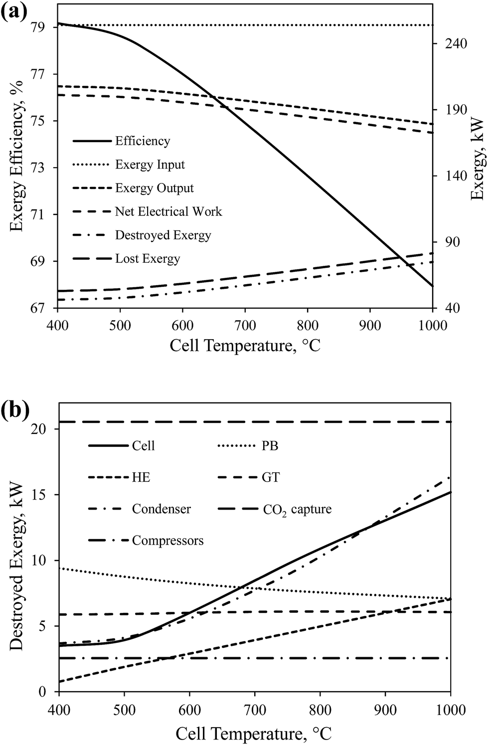 | ||
| Fig. 7 The effect of cell operating temperature on (a) the overall exergy efficiency and global exergy flows of CH4-SOFC, and (b) the destroyed exergy in each device. | ||
The effect of cell temperature on the destroyed exergy in each device in CH4-SOFC was shown in Fig. 7(b). The amount of destroyed exergy in CO2 capture and compressors remains constant. The increase in the total destroyed exergy in the whole process was mainly attributed to the condenser, cell and HE. Among the three devices, the destroyed exergy in the condenser increases at the highest rate. This is mainly because a higher temperature is reached by the exhaust steam (node 10 in Fig. 2) and more heat is wasted in the condenser during cooling. Also, a higher cell temperature also increases the heat transfer occurred in the cell and HE, which consequently leads to more exergy destruction in these two devices.
The data presented in Fig. 7(a) and (b) indicate that decreasing the working temperature of the SOFCs increases the exergy efficiency of the system, which demonstrates the necessity to develop novel solid electrolyte materials capable of delivering oxygen at lower temperatures.
Fig. 8(a) shows the effect of the cell operating pressure on the overall exergy efficiency and the global exergy flows of CH4-SOFC. The overall exergy efficiency increases gradually from 71.0% to 75.3% with increasing the cell pressure from 2 to 20 atm. This is mainly resulted from the increase in net amount of electricity produced in the process from 180 kW to 191 kW and the corresponding decrease in the amount of destroyed exergy from 67.2 kW to 56.2 kW. Increasing the cell pressure increases the electrical work produced in both the cell and GT. When the operating pressure is above 10 atm, the increase in the overall exergy efficiency with increasing pressure becomes less significant. This is because above 10 atm the net amount of electricity produced in the process increases at a lower rate, while the consumption rate of electricity in compressors increases linearly.
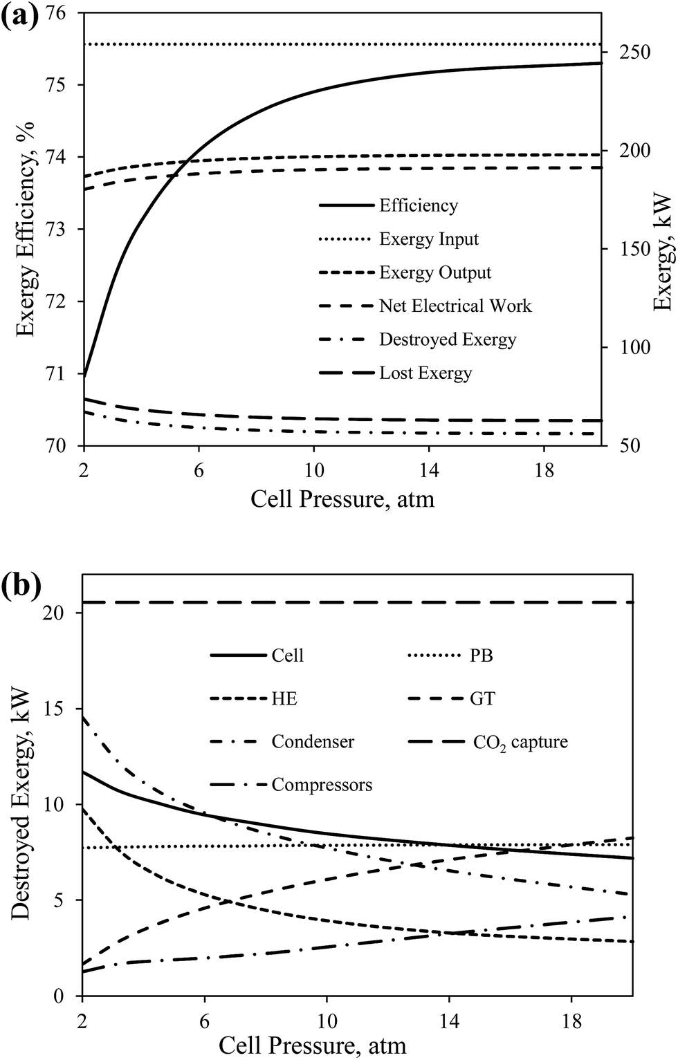 | ||
| Fig. 8 The effect of cell operating pressure on (a) the overall exergy efficiency and global exergy flows of CH4-SOFC, and (b) the destroyed exergy in each device in CH4-SOFC. | ||
The effect of cell pressure on the destroyed exergy in each device was shown in Fig. 8(b). The decrease in the total destroyed exergy of the process is mostly contributed to the cell, HE and condenser. The decrease in the heat duties in the condenser decreases the destroyed exergy in the device. Also, the temperature of the preheated air (node 5 in Fig. 2) increases with the increase in the cell pressure. This decreases the temperature difference of heat transfer in the HE and cell, which correspondingly results in less exergy destruction in the two devices.
Fig. 9(a) and (b) show the effect of the air flow rate into the cathode compartment on the overall exergy efficiency and the global exergy flows of CH4-SOFC. The exergy efficiency reaches the maximum of 74.9% when the air flow rate is 14.5 kmol h−1. The total amount of electricity produced by the cell (Wcell) and GT (WGT) increases gradually with increasing the air flow rate from 10 to 30 kmol h−1. The growth of the produced electricity by the cell slows down when the air flow rate exceeds about 14 kmol h−1, while the consumed electricity in compressors (Wcompressors) increases with increasing the air flow rate at a higher rate. Therefore, there is a trade-off between the increased electrical work produced by the cell and GT and the consumed work by compressors, which forms the peak total net electricity produced (Wcell) when the air flow rate is 14.5 kmol h−1. Also, the destroyed exergy reaches the lowest at the same air flow rate.
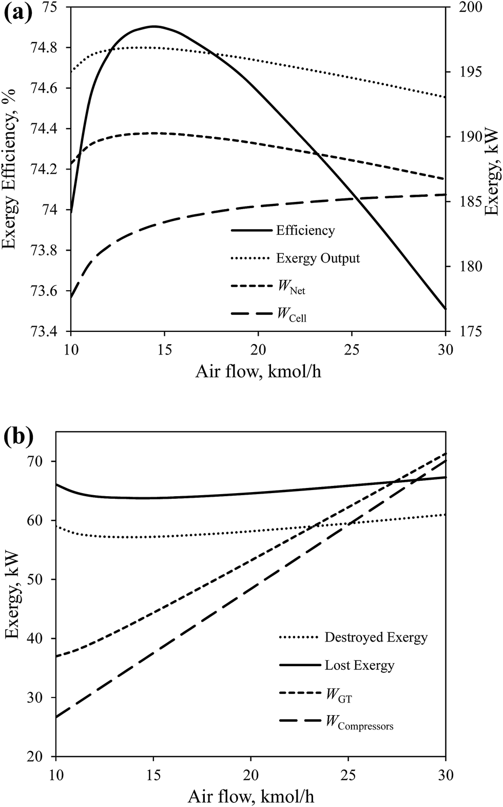 | ||
| Fig. 9 The effect of the air flow rate on the overall exergy efficiency and global exergy flows of CH4-SOFC. | ||
The effect of air flow rate on the destroyed exergy in each device in CH4-SOFC is shown in Fig. 10. Along with increasing the air flow rate, the temperature of preheated air gradually decreases to keep the operating temperature of the cell constant. This decreases the temperature difference of the heat transfer and the destroyed exergy in the cell although increases the heat duty of the HE, leading to more destroyed exergy in the HE. A higher air flow rate also increases the produced electricity and unavoidably increases the destroyed exergy in the GT. Furthermore, an increase in the net electricity produced in the whole process results in less energy carried by the exhaust stream (node 10 in Fig. 2), which correspondingly decreases the destroyed exergy in the condenser.
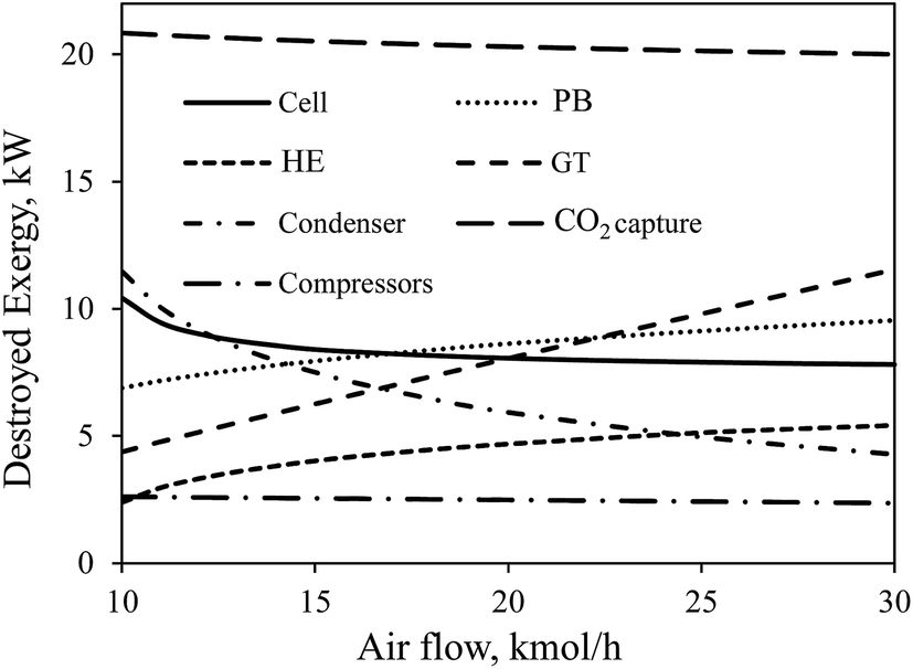 | ||
| Fig. 10 The effect of the air flow rate on the destroyed exergy in each device in CH4-SOFC. | ||
3.2 Comparison of the four SOFC processes using CH4 as the original fuel
To feed a H2 fuelled SOFC system, H2 can be produced from hydrocarbons particularly natural gas, and the loss of energy unavoidably occurs during a H2 production process. It is necessary to compare the exergy utilization of the integrated H2-SOFC process starting with CH4 fuel with other fuel cell processes directly using CH4 as fuel (as presented in Fig. 1).The process simulation and thermodynamics of SMR have been thoroughly studied. The exergy efficiency of SMR, φSMR, is defined as the ratio of exergy in hydrogen product to the total exergy input to the system. A summary of the exergy efficiencies of SMR systems reported in literature has been made previously.9 The average value of the exergy efficiency of these SMR systems is 70.1% which is used in this work.
Muradov28 introduced a circulating fluidized bed reactor for H2 production by a MC process which is performed at 850–950 °C and 10–20 atm. The required heat for MC can be produced by the combustion of additional methane or non-permeate gas. The exergy efficiency φMC is defined as the ratio of exergy in the produced hydrogen and carbon to the total exergy input to the system. In light of Muradov's model, we proposed a novel MC process integrated with a CLC. In this MC process, a CLC unit is employed to supply heat to endothermic methane cracking reaction and CO2 capture simultaneously.9 The performance of this MC process is evaluated using exergy analysis and a high exergy efficiency of 91% is reached. The novel MC model9 is used in this work.
Direct carbon fuel cell (DCFC) is the only fuel cell capable of converting solid carbon into electricity without a reforming process. In comparison with H2-based fuel cells, DCFC has the great thermodynamic advantage of a near-zero entropy change at a high temperature. Even under practical conditions, a efficiency of 80% can be reached in a DCFC system.29,30
Fig. 11 presents the simplified exergy flow diagrams of the four SOFC processes using CH4 as original fuel. In general, CH4-SOFC and CH4-SOFC-CLC processes which directly use CH4 as the fuel of cells have higher exergy efficiencies than SMR-SOFC and MC-SOFC-DCFC, as a large amount of exergy is destroyed in the H2 production processes. CH4-SOFC-CLC obtains the highest exergy efficiency among the four processes, reaching 82.6%. It is followed by CH4-SOFC, which has a lower exergy efficiency of 74.9% mainly because of the energy loss in the CO2 capture unit.
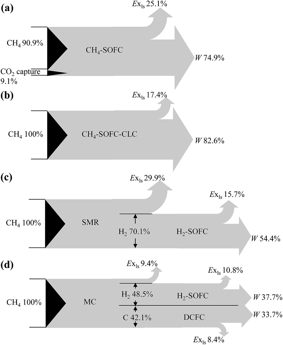 | ||
| Fig. 11 Simplified exergy flow diagrams of the four SOFC processes using CH4 as the original fuel. | ||
MC-SOFC-DCFC obtains an overall exergy efficiency of 71.4%, which is in good consistent with that of Liu's MC-IRSOFC-DCFC model (68.2%).8 SMR-SOFC has the lowest efficiency of 54.4% which is 17% lower than that of MC-SOFC-DCFC. SMR process alone causes a loss of 29.9% of total exergy delivered into the whole process, leading to the low exergy efficiency of SMR-SOFC. MC process has a higher exergy efficiency than SMR mainly owing to the relatively higher reactant utilization of MC. Theoretically, in MC methane can be totally utilized to produce hydrogen and carbon; while in SMR, the carbon in methane is reacted to carbon dioxide without the capability of producing electricity. Besides, more heat is required for the SMR reaction than the decomposition of methane, which results in a higher fraction of methane consumption in heat provision and increases the complexity of heat integration, leading to further decrease in the exergy efficiency of the whole SMR-SOFC system.
4. Conclusions
Exergy analysis is carried out on four different solid oxide fuel cell (SOFC) processes which use methane as the original fuel. The effect of operating parameters on the performance of CH4-SOFC is also examined.The CH4-SOFC-CLC system and CH4-SOFC system without CO2 capture have similar high exergy efficiency, 81.4% and 81.6% respectively. When a CO2 capture unit is attached to the latter, its exergy efficiency is decreased by 7.5%. The H2-SOFC system has an exergy efficiency of 77.6% which is lower than that of CH4-SOFC-CLC system. It is also found that lower cell temperature and higher cell pressure result in increased overall exergy efficiency of CH4-SOFC.
When the H2 production processes are integrated into the H2-SOFC system, the formed SMR-SOFC and MC-SOFC-DCFC processes have even lower efficiencies, as a large amount of exergy is destroyed in H2 production. MC-SOFC-DCFC obtains an overall exergy efficiency of 71.4%, which is 17% higher than that of SMR-SOFC (54.4%). This is mainly contributed to the higher exergy efficiency of MC than SMR.
The results of this investigation demonstrate that the development of methane directly fuelled SOFC, decreasing its operating temperature and proper capture of CO2 are key technologies to improve the energy performance of SOFC systems.
Acknowledgements
The authors gratefully acknowledge the support of the Fundamental Research Funds for the Central Universities (FRF-TP-16-036A1).References
- S. Park, J. M. Vohs and R. J. Gorte, Direct oxidation of hydrocarbons in a solid-oxide fuel cell, Nature, 2000, 404, 265–267 CrossRef CAS PubMed
.
- F. Calise, M. Dentice d'Accadia, A. Palombo and L. Vanoli, Simulation and exergy analysis of a hybrid solid oxide fuel cell (SOFC)-gas turbine system, Energy, 2006, 31, 3278–3299 CrossRef CAS
- J. Huijsmans, F. Van Berkel and G. Christie, Intermediate temperature SOFC – a promise for the 21st century, J. Power Sources, 1998, 71, 107–110 CrossRef CAS
- A. P. Simpson and A. E. Lutz, Exergy analysis of hydrogen production via steam methane reforming, Int. J. Hydrogen Energy, 2007, 32, 4811–4820 CrossRef CAS
- J. Fan and L. Zhu, Performance analysis of a feasible technology for power and high-purity hydrogen production driven by methane fuel, Appl. Therm. Eng., 2015, 75, 103–114 CrossRef CAS
- A. M. Dunker, S. Kumar and P. A. Mulawa, Production of hydrogen by thermal decomposition of methane in a fluidized-bed reactor-effects of catalyst, temperature, and residence time, Int. J. Hydrogen Energy, 2006, 31, 473–484 CrossRef CAS
- Q. Liu, Y. Tian, H. Li, L. Jia, C. Xia and L. T. Thompson, et al., High efficiency chemical energy conversion system based on a methane catalytic decomposition reaction and two fuel cells: part I. Process modeling and validation, J. Power Sources, 2010, 195, 6539–6548 CrossRef CAS
- Q. Liu, Y. Tian, H. Li, L. Jia, C. Xia and L. T. Thompson, et al., High efficiency chemical energy conversion system based on a methane catalytic decomposition reaction and two fuel cells: part II. Process exergy analysis, J. Power Sources, 2010, 195, 6532–6538 CrossRef CAS
- Z. Wang, W. Fan, G. Zhang and S. Dong, Exergy analysis of methane cracking thermally coupled with chemical looping combustion for hydrogen production, Appl. Energy, 2016, 168, 1–12 CrossRef CAS
- L. Zhu, P. Jiang and J. Fan, Comparison of carbon capture IGCC with chemical-looping combustion and with calcium-looping process driven by coal for power generation, Chem. Eng. Res. Des., 2015, 104, 110–124 CrossRef CAS
- H. J. Ritcher and K. F. Knoche, in Reversibility of combustion process, ed. R. A. Gaggioli, ACS Symposium Series 235, Washington DC, 1983, pp. 71–85 Search PubMed
- J. Adanez, A. Abad, F. Garcia-Labiano, P. Gayan and F. Luis, Progress in chemical-looping combustion and reforming technologies, Prog. Energy Combust. Sci., 2012, 38, 215–282 CrossRef CAS
- M. Tang, L. Xu and M. Fan, Progress in oxygen carrier development of methane-based chemical-looping reforming: a review, Appl. Energy, 2015, 151, 143–156 CrossRef CAS
- M. Ishida, D. Zheng and T. Akehata, Evaluation of a chemical-looping-combustion power-generation system by graphic exergy analysis, Energy, 1987, 12, 147–154 CrossRef CAS
- M. Anheden and G. Svedberg, Exergy analysis of chemical-looping combustion systems, Energy Convers. Manage., 1998, 39, 1967–1980 CrossRef CAS
- M. Rydén and A. Lyngfelt, Using steam reforming to produce hydrogen with carbon dioxide capture by chemical-looping combustion, Int. J. Hydrogen Energy, 2006, 31, 1271–1283 CrossRef
- M. R. Rahimpour, M. Hesami, M. Saidi, A. Jahanmiri, M. Farniaei and M. Abbasi, Methane steam reforming thermally coupled with fuel combustion: application of chemical looping concept as a novel technology, Energy Fuels, 2013, 27, 2351–2362 CrossRef CAS
- J. A. Medrano, V. Spallina, M. van Sint Annaland and F. Gallucci, Thermodynamic analysis of a membrane-assisted chemical looping reforming reactor concept for combined H2 production and CO2 capture, Int. J. Hydrogen Energy, 2014, 39, 4725–4738 CrossRef CAS
- M. Rydén, Hydrogen production from fossil fuels with carbon dioxide capture, using chemical-looping technologies, PhD thesis, Chalmers University of Technology, Sweden, 2008
- P. Roohi, R. Alizadeh and E. Fatehifar, Thermodynamic study of transformation of methane to synthesis gas over metal oxides, Int. J. Thermophys., 2015, 36, 88–103 CrossRef CAS
- S. Chen, N. Lior and W. Xiang, Coal gasification integration with solid oxide fuel cell and chemical looping combustion for high-efficiency power generation with inherent CO2 capture, Appl. Energy, 2015, 146, 298–312 CrossRef CAS
- P. G. Bavarsad, Energy and exergy analysis of internal reforming solid oxide fuel cell-gas turbine hybrid system, Int. J. Hydrogen Energy, 2007, 32, 4591–4599 CrossRef CAS
- S. Motahar and A. A. Alemrajabi, Exergy based performance analysis of a solid oxide fuel cell and steam injected gas turbine hybrid power system, Int. J. Hydrogen Energy, 2009, 34, 2396–2407 CrossRef CAS
- U. Desideri and A. Paolucci, Performance modelling of a carbon dioxide removal system for power plants, Energy Convers. Manage., 1999, 40, 1899–1915 CrossRef CAS
- S. McIntosh and R. J. Gorte, Direct hydrocarbon solid oxide fuel cells, Chem. Rev., 2004, 104, 4845–4866 CrossRef CAS PubMed
- J. Szargut, D. R. Morris and F. R. Steward, Exergy analysis of thermal, chemical, and metallurgical processes, Hemisphere Publishing Corporation, New York, 1987 Search PubMed
- M. Rosen, Thermodynamic investigation of hydrogen production by steam-methane reforming, Int. J. Hydrogen Energy, 1991, 16, 207–217 CrossRef CAS
- N. Muradov, Hydrogen via methane decomposition: an application for decarbonization of fossil fuels, Int. J. Hydrogen Energy, 2001, 26, 1165–1175 CrossRef CAS
- X. Li, Z. Zhu, J. Chen, R. De Marco, A. Dicks and J. Bradley, et al., Surface modification of carbon fuels for direct carbon fuel cells, J. Power Sources, 2009, 186, 1–9 CrossRef CAS
- G. A. Hackett, J. W. Zondlo and R. Svensson, Evaluation of carbon materials for use in a direct carbon fuel cell, J. Power Sources, 2007, 168, 111–118 CrossRef CAS
| This journal is © The Royal Society of Chemistry 2017 |