DOI:
10.1039/C7RA05204A
(Paper)
RSC Adv., 2017,
7, 30142-30151
Graphene-decorated silica stabilized stearic acid as a thermal energy storage material†
Received
8th May 2017
, Accepted 4th June 2017
First published on 9th June 2017
Abstract
Novel thermal energy storage materials were synthesized from graphene-decorated silica (SG) and stearic acid (SA) by vacuum impregnation method. Three kinds of SG (SG1, SG5, and SG10) were prepared by decorating silica with different contents of graphene and were then used to stabilize SA to prepare SA/SG1, SA/SG5, and SA/SG10 composites. The structures and thermal energy storage performances of the SA/SG composites were investigated. It is of interest that the thermal energy storage behaviors of the SA/SG composites were dramatically changed with different contents of graphene, presenting more than one endothermal or exothermal peak in the differential scanning calorimetry (DSC) curves while pure SA had only one. The SA in SA/SG1 and SA/SG5 showed higher crystallinity (Fc, 84.44% and 84.39%) and greater effective energy storage per unit mass (Eef, ∼150 J g−1) than that of SA in SA/SG10. These thermal energy storage behaviors and properties were revealed to be related to the pore structures of the SG. The thermal stability of the SA/SG composites was analyzed by a thermogravimetric analyzer (TGA), and the SA/SG composites have good thermal stability. Addition of graphene was beneficial to the enhancement in thermal conductivity of the SA/SG composite, which could reach 0.90 W m−1 K−1, 1.05 W m−1 K−1, and 1.12 W m−1 K−1 for SA/SG1, SA/SG5, and SA/SG10, respectively; and were 246%, 304%, and 331% higher than pure SA, respectively. SA/SG5 has potential for application in thermal energy storage, especially in thermal gradients due to it having both high Eef and thermal conductivity.
1. Introduction
Energy storage is nowadays considered as a key element in the modern energy supply chain, and research on energy storage technologies has been gaining more and more attention.1–5 Thermal energy storage (TES) has been recognized as one of the most efficient ways to enhance the energy efficiency and to relieve the mismatch between energy supply and demand.6–8 TES works by heating thermal energy storage materials (TESMs) during a charging period and then releasing the heat when the energy is needed.8 Thus, TESMs play a crucial part in thermal energy storage systems, including thermal management application.9,10 Finding new TESMs has become more and more important. Phase change materials (PCMs) are a good choice for thermal energy storage systems because the PCMs have high energy storage density and can storage energy in isothermal process.11 Nevertheless, PCMs still have some disadvantages, including the leakage during the phase change process and low thermal conductivity of most PCMs, which limit their wide application for thermal energy storage.11–13 Stabilizing PCMs with supporting matrix (e.g., carbon materials, metal or their oxides, porous structure materials, nanomaterials, etc.) into form-stable composite PCMs is the most promising practical method to overcome these problems.6,11,14–21
Silica-based materials has been used as supporting matrix due to it can make liquid PCMs easy to handle and protect PCMs from harmful interactions with the surrounding materials and environment during the phase change process.22 Fang et al. successfully used silicon dioxide or silica shell to stabilize n-hexadecane,23 lauric acid,24 and octadecane,11 respectively, and the thermal storage capacities of the prepared composite PCMs were 100–230 J g−1. Chung et al.25 successfully impregnated octadecane and BioPCM into the pore of micronized silica and the prepared composite PCMs also had considerable thermal storage capacities (86.07–108.1 J g−1). The octadecane and BioPCM molecules were held easily into the pore of micronized silica by these physical interactions and thus leakage of the melted PCM from the porous was prevented. Wang et al.26 skillfully impregnated stearic acid into the silica fume matrix and its thermal storage capacity was 84.47 J g−1 while the maximum percentage of stearic acid in the composite was 46 wt%. Jeong et al.27 also utilized the silica fume to support hexadecane, octadecane, and paraffin, respectively. The thermal storage capacities of the prepared composite PCMs were 50–90 J g−1 and they were useful for applying to building materials. Min et al.22 for the first time used the radial mesoporous silica to support polyethylene glycol, and their thermal storage capacities were 60–120 J g−1 with different contents of PEG. Song et al.28 used the silica shell microencapsulated caprice-stearic acid with a thermal storage capacity of 91.48 J g−1 while the encapsulation ratio was 56.7 wt%, and prepared composite PCMs showed good thermal reliability. Also, the silica shell encapsulated phase change materials were successfully fabricated by Liu et al.29 and the thermal storage capacities were range from 30–110 J g−1 with different encapsulation ratios. These above mentioned silica-based composite PCMs had considerable thermal storage capacities. Therefore, the silica is a promising supporting matrix to stabilize PCMs and prevent the melted PCMs leakage. Also the thermal conductivities of PCMs were improved to 0.6–0.8 W m−1 K−1 by silica.29,30 As an advanced heat transfer organic materials with excellent thermal conductivities, the PCMs preferably has a thermal conductivity above 1 W m−1 K−1, which broadens its wide application for thermal energy storage.31,32
In this paper, in order to enhance the thermal properties of silica-based composite PCMs, we firstly decorated silica by graphene, which has attracted a great deal of attention in recent years because of its high thermal conductivity.33 Then we synthesized novel composite PCMs (SA/SG) from graphene-decorated silica (SG) and stearic acid (SA) by a simple blending and impregnation process. The structures and thermal energy storage performances of the SA/SG composites were investigated. It is of interest that the thermal energy storage behaviors of SA/SG composites were dramatically changed along with different contents of graphene, presenting more than one endothermal or exothermal peaks in the DSC curves while pure SA only one of that. The thermal conductivity of the SA/SG reached 1.12 W m−1 K−1, which was 331% higher than that of pure SA.
2. Experimental
2.1. Materials
Silica sol (SiO2, 30 wt%) was supplied by Research Institute Of Tsinghua University In Shenzhen, China. Graphite was purchased from Qingdao Graphite Co., Ltd., China. KMnO4, H2O2 and NaNO3 were purchased from Xilong Chemical Co., Ltd. H2SO4 and HCl was purchased from Research Institute Of Chemical Industry In Zhuzhou. (3-Aminopropyl)-triethoxysilane (APTS) was purchased from Nanjing Compton Shuguang Organosilicon Chemical Co., Ltd. (China). Stearic acid (SA, CH3(CH2)16COOH) was supplied by Tianjin Hengxing Chemical Reagent Co., Ltd., China.
2.2. Preparation procedures of the composites
Typical procedures were depicted in Fig. 1, including preparation of the SG and the SA/SG composites.
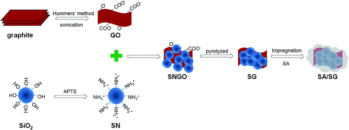 |
| | Fig. 1 Schematic illustration of the preparation process of the SG and SA/SG composites. | |
2.2.1. Preparation of the SG. The SG were prepared from the GO and SN. The GO dispersion was prepared by simple sonication of graphite oxide that was obtained from natural graphite using a modified Hummers' method.34,35 Graphite (2.5 g) and NaNO3 (1.25 g) were mixed with a 95% H2SO4 (60 mL) in a 250 mL flask. The mixture was stirred for 30 min in an ice bath. Under vigorous stirring, 7.5 g of KMnO4 was added to the suspension. The rate of addition was controlled to keep the reaction temperature lower than 20 °C. The ice bath was then removed, and the mixture was stirred at 35 °C for 5 h. Afterward, 150 mL of deionized H2O was slowly added to the mixture still under vigorous agitation. The reaction temperature was observed to rapidly increase to 98 °C. The diluted suspension was stirred for 12 h. Then, 25 mL of 30% H2O2 was added to the mixture. To purify, the mixture was washed with 5% of HCl and then with deionized H2O for several times to obtain the graphite oxide sample. The final GO dispersion was prepared by diluted and sonication of graphite oxide, and concentration of GO is 1 mg mL−1.The SN was prepared by silanizing of SiO2. Silanized of SiO2 with the APTS coupling agent: the silica sol (300 g) was mixed into the 15 mL APTS dissolved in 584 mL DI H2O by stirred at 50 °C for 12 h to ensure completion of the silanization reaction. The obtained product was SiO2–NH2 and labelled as SN (SiO2, 10%).
And then, the silanized silica suspension (SN, 50 g) was slowly added into the GO aqueous dispersion and stirred for 2 h. The obtained slurry was dried at 60 °C for 24 h. The SN-functionalized GO (GO ratio of 1%, 5%, and 10%) was designated as SNGO1, SNGO5, and SNGO10, respectively. Three kinds of SNGO (SNGO1, SNGO5, and SNGO10) were then pyrolyzed at 800 °C under nitrogen atmospheres, generating the SG1, SG5, and SG10, respectively.
2.2.2. Preparation of the SA/SG composites. The composites were prepared using vacuum impregnation method: 3.9 g support (SG1, SG5, and SG10) and 2.1 g SA were placed inside a conical flask (the content of SA in the composites was designed as 35 wt%), and a device of preventing of backward suction was used to connect the conical flask with vacuum pump. The vacuum of conical flask was evacuated to −0.1 MPa for 5 min. Then, the conical flask was placed in thermostatical water bath at 95 °C for 30 min. The vacuum pump was then turned down and allowed the air to enter the flask again, with ultrasonic heating at 80 °C for 10 min. After cooling, composites were obtained and named as SA/SG1, SA/SG5, and SA/SG10, respectively.
2.3. Characterization
The differential scanning calorimetry (DSC) analysis of SA and SA/SG composites was performed using TA Instruments Q2000 at a heating rate of 5 °C min−1 from 20 °C to 80 °C under a constant stream of nitrogen at the atmospheric pressure. Liquid nitrogen was used for cooling the sample during the freezing period. Thermo-gravimetric analysis (TGA) and differential scanning calorimetry (DSC) analysis were conducted at a heating rate of 10 °C min−1 up to 550 °C in nitrogen atmosphere, using α-Al2O3 crucibles in NETZSCH STA 449F3. X-ray diffraction (XRD) was carried out by using a Rigaku D/max-rA analyzer (Cu-Kα) under the following conditions: voltage of 40 kV; current of 40 mA; scan range from 5° to 80° and step size of 0.02°. The thermal conductivity of the samples at room temperature was measured by means of steady-state heat flow method using a thermal conductivity tester (DRX-II-RW, Xiangtan Huafeng Instrument Manufacturing Co., Ltd., Hunan, China).36 The microstructures of the samples were investigated by a JEOL JSM-6360LV scanning electron microscopy (SEM). Fourier transform infrared spectroscopy (FTIR) spectra were recorded by using a Thermo Electron Corporation Nicolet 6700 FTIR spectrometer in the range of 4000–400 cm−1. Nitrogen gas adsorption–desorption isotherms for the SG were measured by an ASAP 2020 surface area and porosimetry system, and the SG samples were outgassed prior to the measurement at 523.15 K and 10−4 mbar for 12 h.
3. Results and discussions
3.1. XRD and FTIR characterization for preparing SG
The XRD patterns of the graphite before and after modified Hummers method were illustrated in Fig. S1.† It is seem that GO showed two diffraction peaks at 2θ = 10.4° and 11.3°, indicating the complete exfoliation of the graphite.34 The XRD patterns of the SiO2 before and after silanized with APTS were illustrated in Fig. S1,† suggesting that the SiO2 still maintained amorphous silica. Fig. S2† showed the XRD patterns of the SNGO before and after pyrolyzed at 800 °C under nitrogen atmospheres. It indicated that the samples kept the amorphous form after pyrolyzed under nitrogen atmospheres. The silica present amorphous form or crystalline form at different atmospheres.37,38 The silica used here pyrolyzed at 800 °C under nitrogen atmosphere and air atmosphere were amorphous form and crystalline form, respectively (Fig. S3†), and these results were in accord with the References.37,38 Fig. S4† showed the FTIR spectrum of the graphite, GO, SiO2, and SN. Compared with the FTIR spectrum of graphite, that of GO exhibited the bands at around 3410 cm−1, 1726 cm−1, 1623 cm−1, 1145 cm−1, and 1114 cm−1, which can be attributed to the oxygen containing functional groups on GO.39 In the FTIR spectrum for the SiO2 and SN, the weakened band at 1384 cm−1 indicated that the APTS bonded to SiO2. The FTIR spectrum of the SNGO and SG were shown in Fig. S5.† It is seem that the bands at 3450 cm−1 and 1630 cm−1 in the SNGO had disappeared after pyrolyzed (see the FTIR spectrum of SG in Fig. S5†), verifying the reduction of GO to G under nitrogen atmospheres.40
3.2. Crystallization characteristics of the SA/SG composites
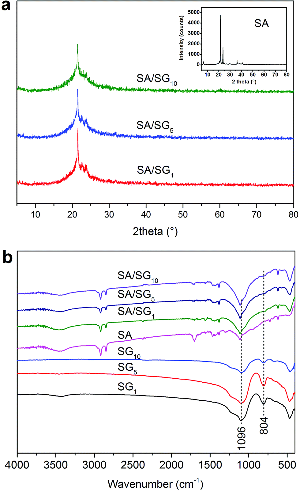
The XRD patterns of the SA/SG composites with different contents of graphene were illustrated in Fig. 2a. The reflections at 2θ = 21.2° and 23.5° were characteristic of the SA (inset of Fig. 2a). After the SA was impregnated into the SG, the characteristic reflections of the SA were observed in the XRD patterns of the SA/SG composites. Comparing the XRD patterns of pure SA (inset of Fig. 2a) and SG (Fig. S2†), a new weak peak emerged at 2θ = 22.6, 22.6, and 23.0 in the SA/SG1, SA/SG5, and SA/SG10, respectively, should be noticed. These peaks suggested a novel interaction between the SA and the SG matrix, which could had an effect on its phase change process.
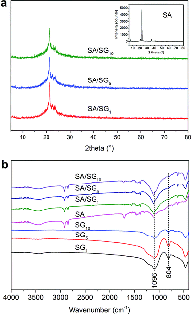 |
| | Fig. 2 (a) XRD patterns of the SA/SG composites and (b) FTIR spectra of the samples. | |
3.3. FTIR analysis of the SA/SG composites
FTIR spectra of the SA, SG, and SA/SG composites were depicted in Fig. 2b. From the spectra of pure SA, the characteristic vibration peaks of the SA were at 2920 cm−1 (–CH3 group symmetrical stretching), 2850 cm−1 (–CH2 group symmetrical stretching), 1704 cm−1 (C![[double bond, length as m-dash]](https://www.rsc.org/images/entities/char_e001.gif) O stretching), 1465 cm−1 (–OH bending), 1382 cm−1 (–OH bending), 1113 cm−1 (CO stretching), 723 cm−1 (–OH swinging), and 680 cm−1 (–OH bending).41,42 From the spectra of the SG1, SG5, and SG10, the characteristic vibration peaks of the SG were at 1096 cm−1 (Si–O–Si asymmetry stretching and), 804 cm−1 (symmetric stretching mode of the Si–O–Si bond), and 463 cm−1 (Si–O–Si bending).38 According to the FTIR spectra of the SA/SG composites, the peak at 804 cm−1 of the SG weakened in the SA/SG composites and the peak at 1096 cm−1 shifted to a higher wavenumber of 1113 cm−1. This phenomenon also suggested a novel interaction between the SA and the SG matrix.
O stretching), 1465 cm−1 (–OH bending), 1382 cm−1 (–OH bending), 1113 cm−1 (CO stretching), 723 cm−1 (–OH swinging), and 680 cm−1 (–OH bending).41,42 From the spectra of the SG1, SG5, and SG10, the characteristic vibration peaks of the SG were at 1096 cm−1 (Si–O–Si asymmetry stretching and), 804 cm−1 (symmetric stretching mode of the Si–O–Si bond), and 463 cm−1 (Si–O–Si bending).38 According to the FTIR spectra of the SA/SG composites, the peak at 804 cm−1 of the SG weakened in the SA/SG composites and the peak at 1096 cm−1 shifted to a higher wavenumber of 1113 cm−1. This phenomenon also suggested a novel interaction between the SA and the SG matrix.
3.4. Morphological investigation of the SA/SG composites
The SEM images and EDS patterns of the SG5 and SA/SG5 were shown in Fig. 3. The irregular particles of SG5 were observed from Fig. 3a and emerged with the size ranges of 0.5–30 μm. A lot of small particles dispersed around the large particles. The EDS patterns of the SG5 (inset of Fig. 3a) suggested that the graphene and the silica were successfully mixed together and the content of the graphene in the SG5 approached the designed value (5%). After the impregnation, the sizes of irregular particles were enlarged by introducing the SA and ranged from 5 μm to 50 μm, indicating from SEM images of the SG5 (Fig. 3b). From the EDS patterns of the SG5 (inset of Fig. 3b), the mass ratio of C element increased due to the added SA and also approached the designed value. By comparing Fig. 3a with 3b, it can be concluded that the surfaces of SG5 were occupied by SA in the SA/SG5, and the SG particles were surrounded by the SA and formed aggregates. Interestingly, some flakes emerged in the smaller particle of the SA/SG5 (Fig. 3c) and also in larger particle of the SA/SG5 (Fig. 3d). It illustrated that the SA was fully adsorbed onto the SG5 and the mass ratio of SA was no overdose.
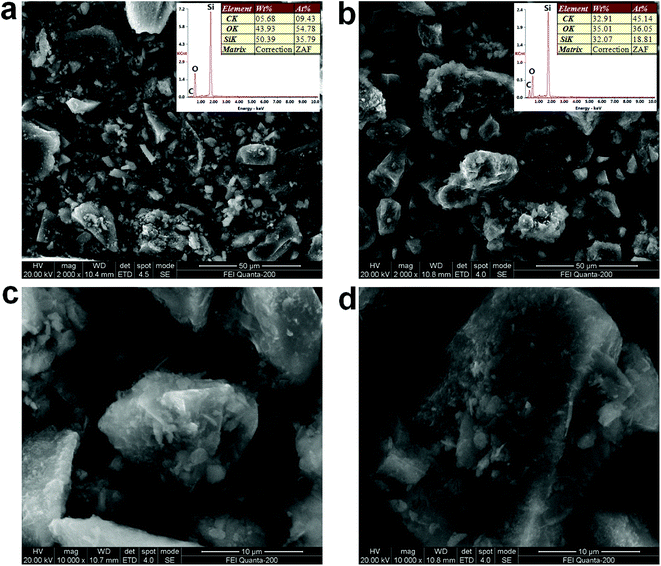 |
| | Fig. 3 SEM images and EDS patterns of the (a) SG5 and (b) SA/SG5; magnified SEM images of (c) smaller particle of the SA/SG5 and (d) larger particle of the SA/SG5. | |
3.5. Thermal stability of the SA/SG composites
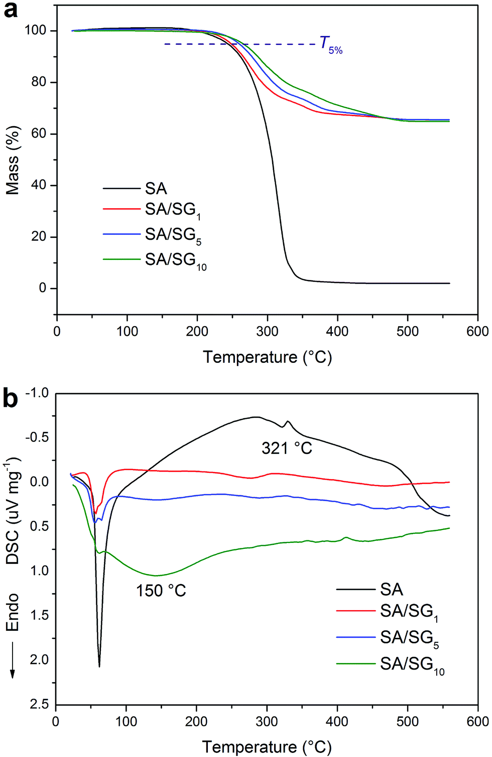
For the application of PCMs, thermal stability determines their practical environment and should be thermally stable over its operating temperature range. So, good thermal stability always is a critical parameter for TES applications. TGA is the most commonly used method to characterize the thermal stability of PCMs.43 Fig. 4 illustrated the TGA-DSC curves of the SA and SA/SG composites. There was a single degradation process for the SA and SA/SG composites due to the decomposition of SA, and no decomposition was observed for the SA/SG composites within 200 °C. In this study, the thermal stability of the SA/SG composites was evaluated with respect to their degradation temperatures (T5%) at which the mass losses were higher than 5% (Fig. 4a). The SA/SG composites degraded at a high temperature of above 247 °C (T5%) and evaporated completely at around 500 °C, while for the SA, a low T5% at 242.3 °C was found and evaporated completely at around 350 °C, indicting SA/SG composites had higher thermal stability than pure SA. That is to say, the thermal stability of the SA in the SA/SG composites was enhanced by the SG matrix. With the content of graphene in SG composites increasing, the T5% of the SA/SG composites also rose and were 247.5 °C, 260.1 °C, and 265.1 °C for SA/SG1, SA/SG5, and SA/SG10, respectively. It indicated that the graphene had an advantage for thermal stability of the SA/SG composite. Compared with the T5% of pure SA, the T5% of the SA/SG1, SA/SG5, and SA/SG10 were about 5.2 °C, 17.8 °C, and 22.8 °C higher than that of SA, respectively. Moreover, the degradation temperature of the SA/SG composites were much higher than their phase change temperatures. It can be concluded that the SA/SG composites had good thermal stability in their operating temperature range or above their melting points. From the corresponding DSC curves (Fig. 4b), a endothermic peak at around 321 °C in the DSC curve of pure SA indicated the SA decomposed. The SA/SG1 and SA/SG5 had same tendency in the DSC curves. But, the DSC curve of SA/SG10 was found to be clearly different from that of the SA/SG1 and SA/SG5: a broad endothermic peak at around 150 °C appeared in the curve while no evident peak in that of the SA/SG1 and SA/SG5 at this temperature interval. This may be related to the interaction between the SA and the SG matrix. Moreover, the exact content of the SA in the SA/SG composites had been confirmed by the TGA. The content of SA in the SA/SG1, SA/SG5, and SA/SG10 were 34.3 wt%, 34.3 wt%, and 34.8 wt%, respectively, which approached the designed value (35 wt%).
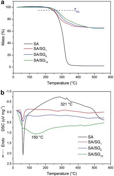 |
| | Fig. 4 TGA (a) – DSC (b) of the SA, SA/SG1, SA/SG5, and SA/SG10. | |
3.6. Thermal energy storage behaviors and properties of the SA/SG composites
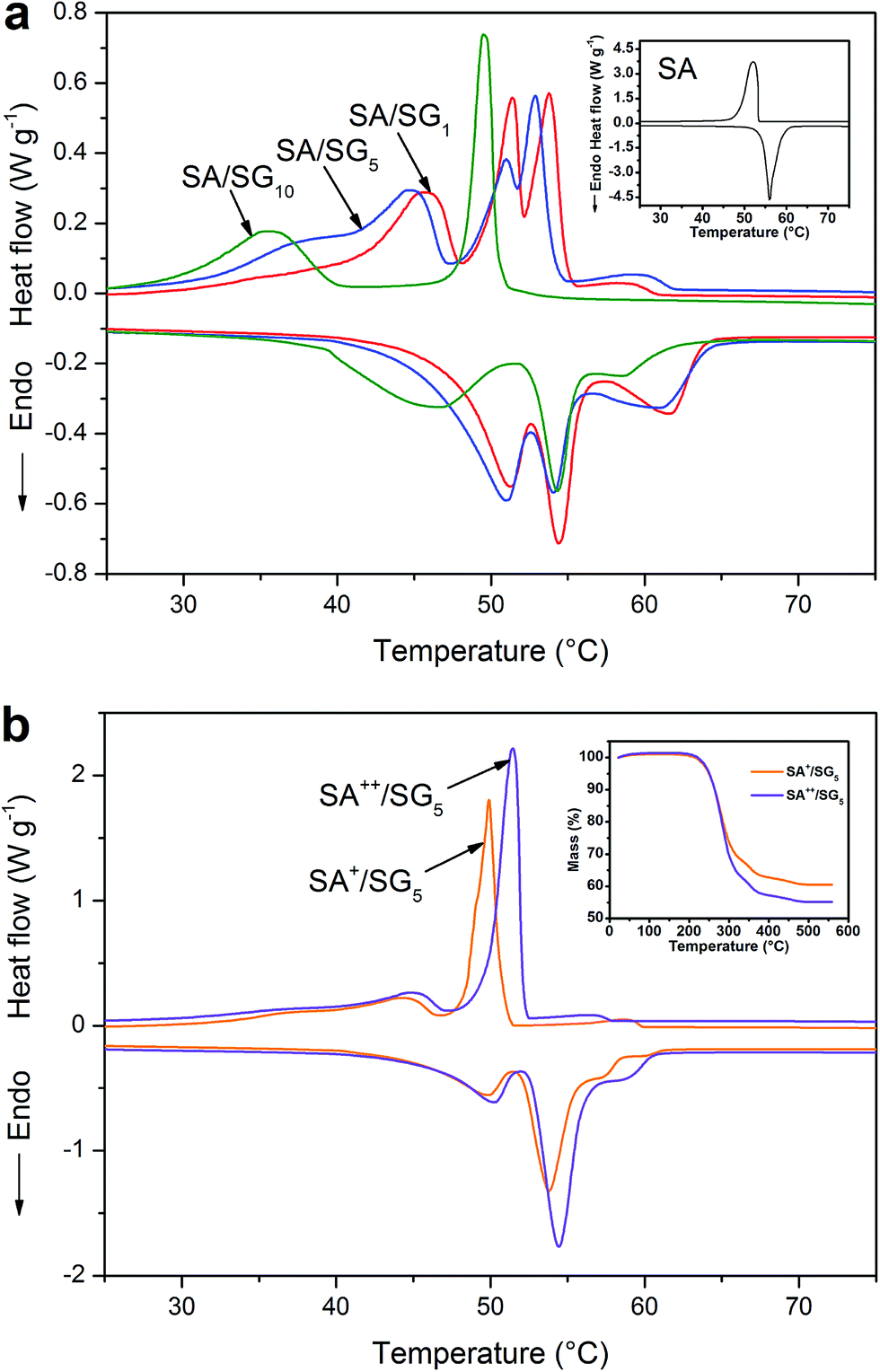
The thermal energy storage behaviors and properties of the SA and SA/SG composites were determined by DSC thermal analysis (Fig. 5a). The onset temperature of each DSC peak was obtained from the intersection of a line at the point of maximum slope of the leading edge of the DSC peak and the extrapolated baseline on the same side of the peak.44 The detailed thermal energy storage properties of the SA and SA/SG composites were given in Table 1. The curve of pure SA (inset of Fig. 5a) showed a melting temperature (Tm) at 54.11 °C in the endothermic curve and a freezing temperature (Tf) at 53.22 °C in the exothermic curve. The latent heats of melting (ΔHm) and freezing (ΔHf) of pure SA were 177.3 J g−1 and 173.8 J g−1, respectively.
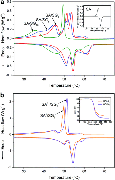 |
| | Fig. 5 (a) DSC curves of the (a) SA, (b) SA/SG1, (c) SA/SG5, and (d) SA/SG10; (b) DSC curves and TG (inset) of the SA+/SG5 and SA++/SG5. | |
Table 1 Thermal properties of the SA and SA/SG compositesa
| Samples |
Loadage (β, wt%) |
Melting temperature (Tm, °C) |
Freezing temperature (Tf, °C) |
Latent heat of melting (ΔHm, J g−1) |
Latent heat of freezing (ΔHf, J g−1) |
Theoretic values of ΔHm (ΔHth, J g−1) |
Crystallinity of SA (Fc, %) |
Efficient energy per unit mass of SA (Eef, J g−1) |
| Note: ΔHth = ΔHpure × β; Eef = ΔHpure × Fc. |
| SA |
100 |
54.11 |
53.22 |
177.3 |
173.8 |
— |
100 |
— |
| SA/SG1 |
34.3 |
47.15/52.16/54.03 |
48.18/52.51/54.92 |
51.35 |
49.83 |
60.81 |
84.44 |
149.7 |
| SA/SG5 |
34.3 |
45.55/51.53/47.91 |
47.24/53.14/54.03 |
51.32 |
49.18 |
60.81 |
84.39 |
149.6 |
| SA/SG10 |
34.8 |
39.03/52.58 |
39.96/50.28 |
37.14 |
33.87 |
61.70 |
60.19 |
106.7 |
The thermal energy storage behaviors are a crucial factor for composite PCMs. Compared with pure SA and the SA/SG composites, it was surprising to find that more than one peak in the endothermic or exothermic curves of the composites (Fig. 5a). The thermal characteristics of the composites were very different from that of pure SA (inset of Fig. 5a), indicating a novel interaction between the SA and the SG matrix,45 which was also reflected in the XRD, FTIR, and TG-DSC results. SA/SG1 had three phase change processes: the phase changes were at 47.15 °C, 52.16 °C, and 54.03 °C in endothermal curve, respectively; the phase changes were 48.18 °C, 52.51 °C, and 54.92 °C in the exothermal curve, respectively. There was a similar phenomenon in the DSC curve of the SA/SG5. But the comparison between the SA/SG1 and the SA/SG5 indicated a tiny difference: the phase change temperature at 47.15 °C, 52.16 °C, and 54.03 °C in endothermal curve shifted to lower temperatures of 45.55 °C, 51.53 °C, and 47.91 °C, respectively (Table 1). Nevertheless, SA/SG10 had two phase change processes: the phase changes were at 39.03 °C and 52.58 °C in endothermal curve, respectively; the phase changes were 39.96 °C and 50.28 °C in the exothermal curve, respectively. A large separation of about 10 °C emerged in the DSC curve of SA/SG10 and the phase change peaks became more defined. For pure SG, there was no endothermal or exothermal peak in the DSC curves (Fig. S6†) in the same temperature range, indicating that SG had no contribution to the phase change peak of the SA/SG composites. From what is discussed above, the thermal energy storage behaviors of the SA were changed by impregnating it into the SG matrix. As further increasing the adding ratio of the graphene in the SG composites (SG1, SG5, and SG10), the thermal energy storage behaviors of the SA/SG composites (SA/SG1, SA/SG5, and SA/SG10) were dramatically changed.
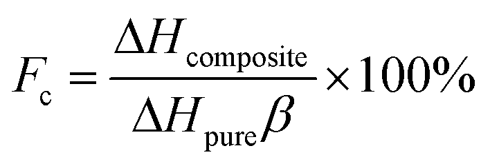
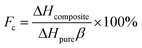
The latent heats of melting and freezing were 51.35 J g−1 and 49.83 J g−1 for SA/SG1, 51.32 J g−1 and 49.18 J g−1 for SA/SG5, and 37.14 J g−1 and 33.87 J g−1 for SA/SG10, respectively, which were less than their corresponding theoretical values (Table 1). The decrease in the latent heats of the composites was not only attributable to the lower fraction of SA within the composites, but could also be related to the crystallinity of the SA in the composites. Crystallization of the SA in the composites may be inhibited by interactions between the SA and the supports, which would also reduce the latent heats of the composites.46 The crystallinity of the SA (Fc) in the composite was calculated by:46–49
| |
 | (1) |
where Δ
Hcomposite and Δ
Hpure were the latent heats of the composites and pure SA, respectively, and
β represented the loading of SA in the composites. The crystallinity of the SA in the SA/SG
1 (84.44%) was close to that in the SA/SG
5 (84.39%), and they were clearly higher than that in the SA/SG
10 (60.19%). According to our previous research,
13,49 it meant that more confined SA (disordered) in the SA/SG
10 composite, comparing with more free SA (ordered) in the SA/SG
1 and SA/SG
5 composites. That is to say, with increasing the adding ratio of the graphene in the SG composites, more SA were confined by the SG. The confined SA cannot crystallize and will not work for thermal energy storage.
49 The effective energy stored per unit mass of the SA (
Eef) was used to evaluate the effectiveness of the SA in different composites (
Table 1). The SA in the SA/SG
1 and in the SA/SG
5 had a adjacent
Eef (∼150 J g
−1) which higher than that of the SA/SG
10 (106.7 J g
−1).
Furthermore, the thermal energy storage properties of the SA/SG composites with different contents of SA were investigated by increasing SA dosage (designed as 40% and 45%) for the SA/SG5 composite. Fig. 5b demonstrated the DSC curves of the SA+/SG5 and SA++/SG5, and the content of SA in the SA+/SG5 and SA++/SG5 were determined as 39.5% and 44.8% by TGA (inset of Fig. 5b). The detailed thermal energy storage properties of the SA+/SG5 and SA++/SG5 were given in Table S1.† Increasing the content of SA to 39.5%, the DSC curve of the SA+/SG5 reduced to two phase change processes (Fig. 5b). Compared to the SA/SG5, the phase change peaks of SA+/SG5 at high temperatures became a single peak and enhancive. As further increasing the content of SA to 44.8%, the phase change peaks at low temperatures shifted to higher temperature zone. Meanwhile, the phase change peaks at high temperatures became more enhancive, which manifested that the incremental SA in the SA++/SG5 had mainly contributed to the phase change enthalpy occurring at the high temperatures. With increasing the content of SA, the crystallinities of SA in composites were enhanced to 86.25% and 88.44% for SA+/SG5 and SA++/SG5, respectively.
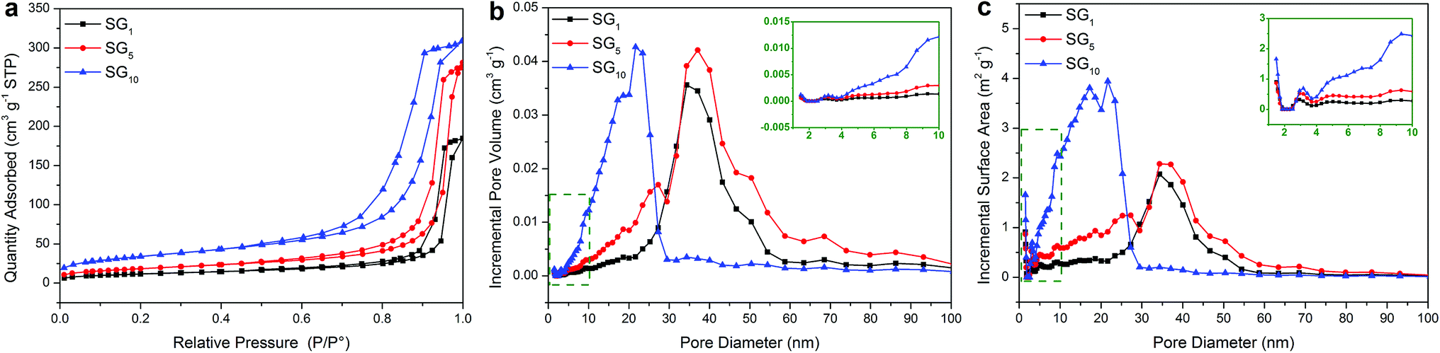
The phenomenon: (a) more than one endothermal or exothermal peak in the DSC curves of SA/SG composites; (b) the Eef decreased while increasing the adding ratio of graphene in the SA/SG10 indicated an interesting question between the SA and the SG matrix. This interesting question may be connected to the special pore structure of the SG matrix on the basis of our previous research.13,49 To unlock this interesting question and further clarify this hypothesis, the pore structure of the SG matrix were depicted in Fig. 6, and the specific surface areas and porous properties of them were listed in Table 2. The specific surface areas of the SG1, SG5, and SG10 were calculated to be 41.29 m2 g−1, 65.29 m2 g−1, and 120.27 m2 g−1, respectively. The results also exhibited that the adsorption cumulative volume of pores and surface area of pores of SG10 were 0.49 cm3 g−1 and 136.38 m2 g−1, respectively, which larger than that of the SG1 and SG5. With increasing the adding ratio of graphene in the SG composites, the adsorption average pore widths of the SG decreased and were 26.16 nm, 24.00 nm, and 14.50 nm for SG1, SG5, and SG10, respectively. Compared with the pore size distributions in incremental pore volume and in incremental surface area of the SG1 and SG5, the SG10 had significantly different pore size distributions while the SG1 and SG5 presented approximately status (Fig. 6b and c). The most pore volume and surface area of the SG10 distributed in the size range of 5 to 30 nm, while that of the SG1 and SG5 appeared in larger size range (20–60 nm). Observing the pore diameters from 5 nm to 30 nm, the SG5 had slightly more pore volume and surface area than that of the SG1, resulting in a tiny difference in the DSC curves (Fig. 5a). After introduced to the supporting matrix, the SA molecules (long hydrocarbon chains) were adsorbed in different size pore. Previous researches have been testified that the phase change temperatures of organic phase change materials decrease as the supporting spaces become narrower.45,50,51 Thus, the SA molecules adsorbed in serial narrower pore exhibited different lower temperature of phase change just like SA/SG1 and SA/SG5 (Fig. 5a). With increasing the adding ratio of graphene in the SG composites, the more pore volume distributed in the small size, the more SA was supported in these pore-size ranges. It resulted in the phase change temperatures further shifted to lower temperature due to the rotation of the hydrocarbon chains require more low thermal energy in this condition.50,51 Compared with the pore size distribution in incremental pore volume of the SG1 and SG5 (20–60 nm and 40 nm), the SG10 had a smaller and concentrated size range (5–30 nm and 25 nm), generating a defined phase change peaks occurring 10 °C lower. Also, the interaction (including surface tension forces and capillary forces) occurred between the SA and the SG matrix would be strong enough to disturb its phase change process when the pore can confine the crystallization of the PCM.49,52 Colligated the above discussions, the different pore structure of the SG matrix could be a reason to more than one endothermal or exothermal peak in the DSC curves of the SA/SG composites. From the inset of Fig. 6b and c, the SG10 had larger pore volume and surface area than that of the SG1 and SG5 in the size range of 1–10 nm, signifying more SA hydrocarbon chains were confined in the SA/SG10. Moreover, the interaction between the SA and the SG matrix of capillary and surface tension forces could affect the crystallization of the SA,49 the larger capillary and surface tension forces between the SA and the SG10 was contributed to the larger BET surface area of the SG10 (Table 2). And then the interaction between the SA and the SG matrix in the SA/SG10 is more than that in the SA/SG1 and SA/SG5. This is consistent with the observation from the thermal stability results (Fig. 4b): the SA/SG10 need greater energy to out of the shackles of the surface of SG10 and then a broad endothermic peak at around 150 °C appeared while no evident peak in that of the SA/SG1 and SA/SG5 at this temperature interval. These then dramatically decreased the crystallinity of the SA in the SA/SG10 composite, comparing with that in the SA/SG1 and SA/SG5 composites. As mentioned above, the confined SA cannot crystallize and will not work for thermal energy storage. So, the Eef decreased while increasing the adding ratio of graphene in the SA/SG10.
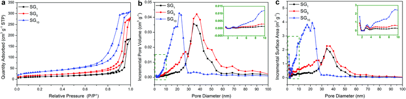 |
| | Fig. 6 (a) Nitrogen adsorption–desorption isotherms of the SG, and BJH pore size distribution for (b) incremental pore volume and (c) incremental surface area. | |
Table 2 Specific surface areas and porous properties of the SG
| Samples |
BET surface area (cm2 g−1) |
BJH adsorption cumulative volume of pores (cm3 g−1) |
BJH adsorption cumulative surface area of pores (cm2 g−1) |
BJH adsorption average pore diameter (nm) |
| SG1 |
41.29 |
0.29 |
44.53 |
26.16 |
| SG5 |
65.29 |
0.43 |
72.40 |
24.00 |
| SG10 |
120.27 |
0.49 |
136.38 |
14.50 |
3.7. Thermal conductivities of the SA/SG composites
The thermal conductivity values were 0.26, 0.90, 1.05, and 1.12 W m−1 K−1 for the SA, SA/SG1, SA/SG5, and SA/SG10, respectively (Table 3). For comparison, the silica without decorated by graphene was prepared and used to support the SA by the same process described in experimental, labeling as SA/SiO2 with a thermal conductivity of 0.58 W m−1 K−1. The comparison between the thermal conductivities of pure SA and the SA/SiO2 demonstrated that SiO2 substrate could improve the thermal conductivity of pure SA by 123%. In order to further enhance the thermal conductivities of the composites, the SiO2 substrate was decorated by graphene. The enhancements in the thermal conductivity compared with that of SA/SiO2 were 55%, 81%, and 93% for the SA/SG1, SA/SG5, and SA/SG10, respectively. The enhancements in the thermal conductivity compared with that of SA were 246%, 304%, and 331% for the SA/SG1, SA/SG5, and SA/SG10, respectively. From the SA/SG1 to the SA/SG5, the thermal conductivity of composites was enhanced by 17%; from the SA/SG5 to the SA/SG10, the thermal conductivity of composites was only enhanced by 7%. These illustrated that with increasing the graphene ratio, thermal conductivity enhancing ability of graphene decreased, and the reason was explained in the following paragraph.
Table 3 Thermal conductivities of the SA and SA/SG composites
| Samples |
SA |
SA/SG1 |
SA/SG5 |
SA/SG10 |
SA/SiO2 |
| λ (W m−1 K−1) |
0.26 |
0.90 |
1.05 |
1.12 |
0.58 |
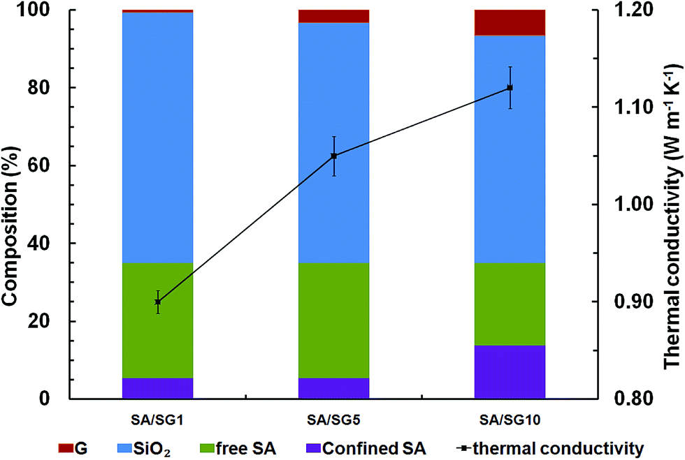
Thermal conductivities of SA/SG composites were governed by phonon propagation, because the composites were blends of the nonmetal (SG) and the organic materials (SA) (Fig. 1).53 For a nonmetallic composite, the ordered or disordered crystals, grain boundary, and interfaces significantly affected the phonon transport.54–57 In particular, the disorder in crystals usually interferes with heat conduction in most materials; thus disordered component tend to have lower thermal conductivity because of strong phonon scattering.58 The components of the SA/SG composites were exhibited in Fig. 7. All the SA/SG composites had a almost same SA loadage (∼35 wt%), but showed a different proportion of the confined SA. The SA/SG5 had a very similar proportion of the confined SA to that of the SA/SG1, and the SA in the SA/SG1 and in the SA/SG5 had a comparative thermal conductivity. The thermal conductivity of the SA/SG5 was obviously (17%) enhanced with increasing the content of graphene (G, 0.65% to 3.25%). But with increasing the content of G, the confined SA in the SA/SG10 reached 13.93%, there are more disordered SA in the composites. The SA in the SA/SG10 had a lower thermal conductivity due to stronger phonon scattering. It deservedly affected the thermal conductivity of the SA/SG10. Therefore, the thermal conductivity of the SA/SG10 were smaller (7%) enhanced with increasing the content of G (3.25% to 6.50%). Thus, thermal conductivity enhancing ability of G in the SA/SG10 decreased.
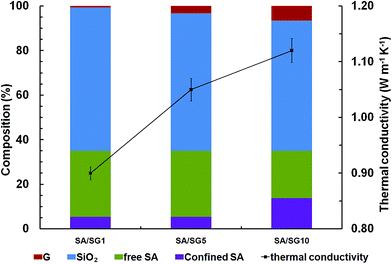 |
| | Fig. 7 The compositions and thermal conductivities of the SA/SG composites. | |
In addition, Table 4 showed the comparison of the latent heats and the thermal conductivities of the prepared composite PCMs with that of silica-based composite PCMs in the literature,59–62 the SA/SG5 composite showed some obvious advantages over the reported materials: added phase change temperatures, considerable latent heat capacities with less PCMs dosage, and higher thermal conductivity (more than 1.0 W m−1 K−1), which broadens its wide application for thermal energy storage. It is remarkably noted that the prepared SA/SG5 composite has potential for application in the thermal energy storage, especially in the thermal gradient using.
Table 4 Comparison of the thermal properties of the as-synthesized composite with the reported materials
| Samples |
Melting temperature, Tm (°C) |
Freezing temperature, Tf (°C) |
Latent heat of melting, ΔHm (J g−1) |
Latent heat of freezing, ΔHf (J g−1) |
Thermal conductivity (W m−1 K−1) |
Reference |
| Poly(ethylene glycol) octadecyl ether (60 wt%)/porous silica |
33.1 |
35.0 |
49.7 |
35.9 |
— |
59 |
| N-octadecane (51.2 wt%)/silica shell |
27.14 |
23.53/16.72 |
108.8 |
98.61 |
0.4403 |
60 |
| N-tetradecane (37.21 wt%)/polystyrene-silica |
2.13 |
0.39 |
83.38 |
79.37 |
0.4035 |
61 |
| N-octadecane (36 wt%)/silica wall |
28.43 |
23.73/20.55 |
40.35 |
37.96 |
0.874 |
62 |
| SA (34.3 wt%)/SG5 |
45.55/51.53/47.91 |
47.24/53.14/54.03 |
51.32 |
49.18 |
1.05 |
This work |
4. Conclusions
Novel thermal energy storage materials (SA/SG1, SA/SG5, and SA/SG10) were synthesized from graphene-decorated silica (SG) and stearic acid (SA) by vacuum impregnation method. The structure and thermal energy storage performances of the SA/SG composites were in detail investigated by XRD, FTIR, SEM-EDS, TG-DSC, DSC, BET, and thermal conductivity. The SA/SG1, SA/SG5, and SA/SG10 composites have good thermal stability and the thermal degradation temperature increased by 5.2 °C, 17.8 °C, and 22.8 °C against pure SA. It is of interest that the thermal energy storage behaviors of the SA/SG composites were dramatically changed along with different contents of graphene, presenting more than one endothermal or exothermal peaks in the DSC curves while pure SA only one of that. The SA in the SA/SG1 and in the SA/SG5 showed greater effective energy storage per unit mass (Eef, ∼150 J g−1) than that of SA in the SA/SG10. These thermal energy storage behaviors and properties were illuminated to be related to the special pore structure of SG matrix by nitrogen gas adsorption–desorption isotherms. Decorating silica by graphene was beneficial to the enhancement in thermal conductivity of the SA/SG composite, and 55%, 81%, and 93% higher than that of SA/SiO2 (without decorated by graphene), respectively; and 246%, 304%, and 331% higher than that of pure SA, for SA/SG1, SA/SG5, and SA/SG10, respectively. The SA/SG5 has potential for application in thermal energy storage, especially in the thermal gradient using due to both the considerable Eef and the high thermal conductivity of 1.05 W m−1 K−1.
Acknowledgements
This work was supported by the National Natural Science Foundation of China (51504041), the Natural Science Foundation of Hunan Province (2016JJ3009), the Scientific Research Fund of Hunan Provincial Education Department (15K007), and the Key Laboratory of Renewable Energy Electric-Technology of Hunan Province (2015ZNDL006 and 2017ZNDL009).
Notes and references
- M. Aneke and M. Wang, Appl. Energy, 2016, 179, 350–377 CrossRef.
- J. Niu, A. Kushima, M. Li, Z. Wang, W. Li, C. Wang and J. Li, J. Mater. Chem. A, 2014, 2, 19788–19796 CAS.
- C. Li, B. Xie, J. Chen, J. He and Z. He, RSC Adv., 2017, 7, 13184–13190 RSC.
- J. Niu, A. Kushima, X. Qian, L. Qi, K. Xiang, Y.-M. Chiang and J. Li, Nano Lett., 2014, 14, 4005–4010 CrossRef CAS PubMed.
- X. Wu, Y. Li, C. Li, Z. He, Y. Xiang, L. Xiong, D. Chen, Y. Yu, K. Sun, Z. He and P. Chen, J. Power Sources, 2015, 300, 453–459 CrossRef CAS.
- L. Liu, D. Su, Y. Tang and G. Fang, Renewable Sustainable Energy Rev., 2016, 62, 305–317 CrossRef CAS.
- Y. Xu, Q. Ren, Z.-J. Zheng and Y.-L. He, Appl. Energy, 2017, 193, 84–95 CrossRef CAS.
- H. Zhang, J. Baeyens, G. Cáceres, J. Degrève and Y. Lv, Prog. Energy Combust. Sci., 2016, 53, 1–40 CrossRef.
- X. Gao, Y. Yuan, X. Cao, H. Wu and X. Zhao, Process Saf. Environ. Prot., 2017, 107, 438–453 CrossRef CAS.
- Y. Yuan, X. Gao, H. Wu, Z. Zhang, X. Cao, L. Sun and N. Yu, Energy, 2017, 119, 817–833 CrossRef.
- F. Tang, L. Liu, G. Alva, Y. Jia and G. Fang, Sol. Energy Mater. Sol. Cells, 2017, 160, 1–6 CrossRef CAS.
- A. Arteconi, N. J. Hewitt and F. Polonara, Appl. Energy, 2012, 93, 371–389 CrossRef.
- C. Li, L. Fu, J. Ouyang and H. Yang, Sci. Rep., 2013, 3, 1908 CrossRef PubMed.
- M. M. Kenisarin and K. M. Kenisarina, Renewable Sustainable Energy Rev., 2012, 16, 1999–2040 CrossRef CAS.
- M. Zhou, T. Lin, F. Huang, Y. Zhong, Z. Wang, Y. Tang, H. Bi, D. Wan and J. Lin, Adv. Funct. Mater., 2013, 23, 2263–2269 CrossRef CAS.
- Y. Wang, B. Tang and S. Zhang, Adv. Funct. Mater., 2013, 23, 4354–4360 CrossRef CAS.
- Y. Zhang, X. Zheng, H. Wang and Q. Du, J. Mater. Chem. A, 2014, 2, 5304 CAS.
- P. Zhang, X. Xiao and Z. W. Ma, Appl. Energy, 2016, 165, 472–510 CrossRef CAS.
- S. F. Ahmed, M. Khalid, W. Rashmi, A. Chan and K. Shahbaz, Renewable Sustainable Energy Rev., 2017, 67, 450–460 CrossRef CAS.
- Y. Yuan, N. Zhang, W. Tao, X. Cao and Y. He, Renewable Sustainable Energy Rev., 2014, 29, 482–498 CrossRef CAS.
- Y. Yuan, T. Li, N. Zhang, X. Cao and X. Yang, J. Therm. Anal. Calorim., 2016, 124, 881–888 CrossRef CAS.
- X. Min, M. Fang, Z. Huang, Y. g. Liu, Y. Huang, R. Wen, T. Qian and X. Wu, Sci. Rep., 2015, 5, 12964 CrossRef CAS PubMed.
- G. Fang, H. Li, Z. Chen and X. Liu, J. Hazard. Mater., 2010, 181, 1004–1009 CrossRef CAS PubMed.
- G. Fang, H. Li and X. Liu, Mater. Chem. Phys., 2010, 122, 533–536 CrossRef CAS.
- O. Chung, S.-G. Jeong, S. Yu and S. Kim, Energ. Build., 2014, 70, 180–185 CrossRef.
- Y. Wang, T. D. Xia, H. Zheng and H. X. Feng, Energ. Build., 2011, 43, 2365–2370 CrossRef.
- S.-G. Jeong, J. Jeon, J. Cha, J. Kim and S. Kim, Energ. Build., 2013, 62, 190–195 CrossRef.
- S. Song, L. Dong, Z. Qu, J. Ren and C. Xiong, Appl. Therm. Eng., 2014, 70, 546–551 CrossRef CAS.
- C. Liu, C. Wang, Y. Li and Z. Rao, RSC Adv., 2017, 7, 7238–7249 RSC.
- H. Zhang, X. Wang and D. Wu, J. Colloid Interface Sci., 2010, 343, 246–255 CrossRef CAS PubMed.
- D.-G. Kang, M. Park, D.-Y. Kim, M. Goh, N. Kim and K.-U. Jeong, ACS Appl. Mater. Interfaces, 2016, 8, 30492–30501 CAS.
- A. I. Fernandez, M. Martínez, M. Segarra, I. Martorell and L. F. Cabeza, Sol. Energy Mater. Sol. Cells, 2010, 94, 1723–1729 CrossRef CAS.
- G.-Q. Qi, C.-L. Liang, R.-Y. Bao, Z.-Y. Liu, W. Yang, B.-H. Xie and M.-B. Yang, Sol. Energy Mater. Sol. Cells, 2014, 123, 171–177 CrossRef CAS.
- Z. B. Lei, L. Lu and X. S. Zhao, Energy Environ. Sci., 2012, 5, 6391–6399 CAS.
- L. L. Zhang, S. Zhao, X. N. Tian and X. S. Zhao, Langmuir, 2010, 26, 17624–17628 CrossRef CAS PubMed.
- J.-L. Zeng, S.-H. Zheng, S.-B. Yu, F.-R. Zhu, J. Gan, L. Zhu, Z.-L. Xiao, X.-Y. Zhu, Z. Zhu, L.-X. Sun and Z. Cao, Appl. Energy, 2014, 115, 603–609 CrossRef CAS.
- X.-G. Chen, S.-S. Lv, P.-P. Zhang, L. Zhang and Y. Ye, J. Therm. Anal. Calorim., 2011, 104, 1055–1062 CrossRef CAS.
- M. M. Haslinawati, K. A. Matori, Z. A. Wahab, H. A. A. Sidek and A. T. Zainal, Int. J. Basic Appl. Sci., 2009, 9, 22–25 Search PubMed.
- Y. Huang and S. F. Y. Li, J. Electroanal. Chem., 2013, 690, 8 CrossRef CAS.
- M. Sun, X. Ma, J. Wang, W. Wang, Q. Wu, C. Wang and Z. Wang, J. Sep. Sci., 2013, 36, 1478–1485 CrossRef CAS PubMed.
- G. Fang, H. Li, Z. Chen and X. Liu, Energy, 2010, 35, 4622–4626 CrossRef CAS.
- M. Ferreira, K. Wohnrath, A. Riul, J. A. Giacometti and O. N. Oliveira, J. Phys. Chem. B, 2002, 106, 7272–7277 CrossRef CAS.
- A. Karaipekli and A. Sarı, Sol. Energy Mater. Sol. Cells, 2016, 149, 19–28 CrossRef CAS.
- S. Karaman, A. Karaipekli, A. Sarı and A. Biçer, Sol. Energy Mater. Sol. Cells, 2011, 95, 1647–1653 CrossRef CAS.
- B. Li, T. Liu, L. Hu, Y. Wang and S. Nie, Chem. Eng. J., 2013, 215–216, 819–826 CrossRef CAS.
- C. Wang, L. Feng, W. Li, J. Zheng, W. Tian and X. Li, Sol. Energy Mater. Sol. Cells, 2012, 105, 21–26 CrossRef CAS.
- C. Wang, L. Feng, H. Yang, G. Xin, W. Li, J. Zheng, W. Tian and X. Li, Phys. Chem. Chem. Phys., 2012, 14, 13233–13238 RSC.
- Q. Cao and P. Liu, Eur. Polym. J., 2006, 42, 2931–2939 CrossRef CAS.
- C. Li, L. Fu, J. Ouyang, A. Tang and H. Yang, Appl. Clay Sci., 2015, 115, 212–220 CrossRef CAS.
- T. Uemura, N. Yanai, S. Watanabe, H. Tanaka, R. Numaguchi, M. T. Miyahara, Y. Ohta, M. Nagaoka and S. Kitagawa, Nat. Commun., 2010, 1, 83 Search PubMed.
- X. Huang, W. Xia and R. Zou, J. Mater. Chem. A, 2014, 2, 19963–19968 CAS.
- Q. Shen, S. Liu, J. Ouyang and H. Yang, RSC Adv., 2016, 6, 112493–112501 RSC.
- C. Li, J. Ouyang and H. Yang, Phys. Chem. Miner., 2013, 40, 681–689 CrossRef CAS.
- C. Poulier, D. S. Smith and J. Absi, J. Eur. Ceram. Soc., 2007, 27, 475–478 CrossRef CAS.
- R. M. Costescu, D. G. Cahill, F. H. Fabreguette, Z. A. Sechrist and S. M. George, Science, 2004, 303, 989–990 CrossRef CAS PubMed.
- L. Xie, X. Huang, K. Yang, S. Li and P. Jiang, J. Mater. Chem. A, 2014, 2, 5244 CAS.
- X. Lu, D. T. Morelli, Y. Xia, F. Zhou, V. Ozolins, H. Chi, X. Zhou and C. Uher, Adv. Energy Mater., 2013, 3, 342–348 CrossRef CAS.
- K. E. Goodson, Science, 2007, 315, 342–343 CrossRef CAS PubMed.
- L. Zhang, H. Shi, W. Li, X. Han and X. Zhang, Thermochim. Acta, 2013, 570, 1–7 CrossRef CAS.
- S. Liang, Q. Li, Y. Zhu, K. Chen, C. Tian, J. Wang and R. Bai, Energy, 2015, 93, 1684–1692 CrossRef CAS.
- W. Fu, X. Liang, H. Xie, S. Wang, X. Gao, Z. Zhang and Y. Fang, Energ. Build., 2017, 136, 26–32 CrossRef.
- F. He, X. Wang and D. Wu, Energy, 2014, 67, 223–233 CrossRef CAS.
Footnote |
| † Electronic supplementary information (ESI) available. See DOI: 10.1039/c7ra05204a |
|
| This journal is © The Royal Society of Chemistry 2017 |
Click here to see how this site uses Cookies. View our privacy policy here. 
 Open Access Article
 This Open Access Article is licensed under a Creative Commons Attribution-Non Commercial 3.0 Unported Licence
 *,
Baoshan Xie and
Jian Chen*
*,
Baoshan Xie and
Jian Chen*