 Open Access Article
One-step synthesis of magnetically recyclable Co@BN core–shell nanocatalysts for catalytic reduction of nitroarenes†
Man Dua,
Qiuwen Liua,
Caijin Huang *a and
Xiaoqing Qiu*b
aState Key Laboratory of Photocatalysis on Energy and Environment, College of Chemistry, Fuzhou University, Fuzhou 350002, P. R. China. E-mail: cjhuang@fzu.edu.cn
bCollege of Chemistry and Chemical Engineering, Central South University, Changsha, 41083, China. E-mail: xq-qiu@csu.edu.cn
First published on 14th July 2017
Abstract
We present a facile one-step synthesis of chemically stable and magnetic Co@BN core–shell nanoparticles. We found that Co@BN nanoparticles acted as excellent catalysts with high stability and magnetic recyclability for reduction of nitroarenes to aminoarenes under mild reaction conditions. The sample 13.6 wt% Co@BN showed the best catalytic activity for reduction of 4-nitrophenol (4-NP). In addition, a significant synergistic effect of the h-BN support was observed during the catalytic reaction by effectively adsorbing/concentrating and ionizing the reactant nitroaromatics. Moreover, the kinetics of the catalytic reaction were investigated at different reaction temperatures, 4-nitrophenol concentrations, sodium borohydride concentrations, metal loadings and catalyst amounts. The activation energy of the catalytic reduction of 4-nitrophenol for 13.6 wt% Co@BN was determined to be 102.93 kJ mol−1. This work provides a clear example of Co@BN core–shell nanoparticles as nanocatalysts.
1. Introduction
In recent years, earth-abundant available transition metal nanoparticles have attracted growing attention in diverse fields of optics,1 magnetics2 and catalysis3 because of their excellent properties. Among these metals, cobalt is particularly interesting for its wide use as catalysts because of its loosely bonded d electrons and the resulting high electrical conductivity.4–7 Searching for larger surface-to-volume ratios and more active sites constitutes part of the driving force in developing nanoscale catalysts. However, for metal nanoparticles, they are inclined to aggregate in aqueous solution owing to surface hydrophobicity,8 resulting in eventual loss of catalytic activity. To solve this problem, extensive efforts have been devoted to stabilizing metal nanoparticles with various capping agents or supports. For instance, Crooks and co-workers demonstrated that metal nanoparticles can be effectively stabilized through macromolecular organic ligands.9 However, organic ligands can not be long-term stable in air, oxidizing solution or at high temperature. Another interesting stabilization strategy is to encapsulate nanoparticles with another material to form a core–shell hetero-structure. While core particles are wrapped with a shell, it causes changes in magnetic, electronic, optical, catalytic and chemical properties compared with those of their individual components.10–13 Consequently, the core–shell structure has enabled a significant enhancement in photoluminescence,14–18 chemical and thermal stability,19 and processibility.20 Moreover, the shell also plays an important role in the core–shell structure to improve the photoluminescence quantum yield,15 exhibit high activity and selectivity in homogenous catalytic reaction,21 and enhance higher biocatalytic activity and temperature stability.22 Somorjai et al. demonstrated when Pt core is coated with a silica shell, it possesses excellent thermal stability and high catalytic performance for high-temperature reactions.23 Oelhafen et al. reported that the metallic Co core surround by oxide shell can avoid directly exposing to the air and have the property to exchange the magnetic system.24 The use of reduced graphene oxide (rGO) as a shell protects the core Cu nanoparticle from oxidation and the as-prepared Cu@rGO nanoparticles exhibit excellent catalytic performance towards the reduction of 4-nitrophenol.25 Encouragingly, as an analogue to graphene,26 hexagonal boron nitride (h-BN) sheets have been used as a shell in our previous work to wrap Cu nanoparticles and the as-obtained Cu@BN core–shell nanoparticles possesses good catalytic performance and high chemical stability.27Two-dimensional (2D) h-BN material has attracted great interest owing to its nontoxicity, high surface area, appropriate chemical anchoring sites, chemical and thermal stability.28–30 Moreover, h-BN has been found to be an excellent support for functional materials to promote their (photo)-catalytic performance.31–33 Recently, Lei et al. showed that h-BN can serve as an excellent adsorbent material because of its good adsorption performance of organic compounds.30 For heterogeneous catalytic process, concentrating reactants (e.g. organic compounds) in the vicinity of the catalyst is beneficial for improving catalytic reaction rate. In this regard, h-BN was used in this work as a promising shell material to wrap/stabilize cobalt nanoparticles for catalyzing organic compounds.
Amino-aromatics are widely employed in dyes, pharmaceutical, polymers and herbicides.34–38 For example, 4-chloroaniline plays a significant role in the production of dyes.36 In addition, 4-aminophenol (4-AP) is an important intermediate in the preparation of analgesic and antipyretic drugs,39,40 and also used as a photographic developer, a corrosion inhibitor and an antioxidant.41,42 Meanwhile, nitro-aromatics are considered to be over 500-fold more toxic than their corresponding aromatic amines.43 Therefore, conversion of nitro-aromatics to amino-aromatics is of great importance for the industrial production of amino compounds and industrial waste water treatment of nitro-compounds. The catalytic hydrogenation of nitro-aromatics is an attractive conversion pathway and has been widely studied by using noble-metal based catalysts including Ag and Au.44,45 In this paper, we report a new type of nanocomposite, composed of a magnetic metal core, Co, and an insulating shell, hexagonal boron nitride (h-BN). The as-prepared Co@BN core–shell nanoparticles were introduced as catalysts for hydrogenation of nitroarenes (e.g. 4-nitrophenol, 4-nitroaniline and 4-nitroanisole) to their corresponding aminoarenes. The experimental results showed that the as-synthesized Co@BN nanoparticles acted as excellent catalysts with high durable stability for reduction of nitroarenes to aminoarenes under mild reaction conditions. The core–shell structure and magnetic property of Co core enabled easy separation from the reaction mixture. Moreover, effects of reactant concentration, metal loading, catalyst amount and reaction temperature on reaction rate and activation energy were studied as well.
2. Experimental
2.1 Materials
Boron oxide, urea and cobalt(II) nitrate were used as the raw materials in the preparation of Co@BN composites. Boron oxide was purchased from Aladdin Company. Cobalt(II) nitrate hexahydrate (Co(NO3)2·6H2O ≥ 47.8%) was used as cobalt precursor. Urea, 4-nitrophenol and sodium borohydride (NaBH4) were obtained from Sinopharm Chemical Reagent Corporation. All other chemicals were of analytical grade and used without further purification. Deionized water was used throughout the study.2.2 Catalyst preparation
The synthesis of Co@BN composites is indicated as follows: different amounts of cobalt nitrate (0.09, 0.9, 1.8 and 2.7 g, respectively), 3 g of boron oxide and 6 g of urea were mixed in the mortar until it was ground into a fine powder. The resultant powder was placed in a tube furnace with sintering temperature at 1250 °C for 5 h. The cobalt contents in Co@BN composites were detected by the Ultima2 ICP optical emission spectrometer. According to the corresponding cobalt contents, the samples were denoted as 0.94 wt% Co@BN, 8.3 wt% Co@BN, 13.6 wt% Co@BN and 20.0 wt% Co@BN, respectively. For contrast experiments, the sample cobalt without h-BN was prepared as the procedure mentioned above by placing 1.8 g cobalt nitrate in a tube furnace without adding boron oxide and urea.2.3 Catalyst characterization
The crystal structure of the samples was recorded with an X-ray powder diffractometer (XRD, Bruker, D8 Advance, Cu-Kα1 radiation). Fourier transformed infrared (FTIR) spectroscopy was conducted on a Nicolet Magna 670 Fourier transform infrared spectrometer at room temperature. Raman spectra were recorded by Raman spectrometer (Renishaw inVia Raman Microprobe) with an excitation source at 532 nm. Transmission Electron Microscope (TEM) and selected-area electron diffraction (SAED) characterization were taken on TITAN G2 60–300 electron beam aberration corrected transmission electron microscope under an acceleration voltage of 300 kV. Magnetic hysteresis loops were measured on a Physical Property Measurement System (PPMS-9T, Quantum Design, USA). Nitrogen sorption measurements and pore size analysis were performed on a Micromeritics ASAP 2020 HD88 system. The sample was degassed at 180 °C for 8 h prior to the experiment. The electron paramagnetic resonance (EPR) spectra were observed by Bruker A300 spectrometer at room temperature.2.4 Catalytic activity measurements
Considering the precision of the experiment, aqueous solutions of 4-nitrophenol and NaBH4 were freshly prepared prior to being used. Typically, 35 ml of the deionized water, 4 ml of nitroarenes (e.g. 4-nitrophenol) solution (100 ppm), 3 ml of NaBH4 solution (0.2 mol l−1) and 10 mg of the catalyst were added to a 100 ml beaker with stirring. Every 2 min, 1.5 ml of the reaction mixture was injected into a 2 ml centrifuge tube immediately through a pressure syringe filter which can remove the catalyst from the reaction solution and end the reaction. The filtrated solution was then measured by using a conventional UV-visible spectrometer (Cary 50, VARIAN) using deionized water as a blank solution.3. Results and discussion
3.1 Structure characterization, morphology and magnetism
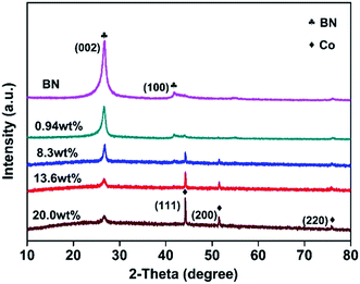
Fig. 1 displays the XRD patterns of the as-obtained h-BN and Co@BN samples. The characteristic peaks of h-BN sample located at 26.7 and 42° are assigned to the (002) and (100) crystalline facets, respectively (JCPDS card no. 45-0896). The diffraction peaks of Co@BN at around 44.2, 51.5 and 75.8° correspond to the (111), (200) and (220) planes of the cubic phase cobalt, respectively (JCPDS card no. 15-0806). Moreover, the intensity of the peak at 44.2° for cobalt increases with increasing amount of the cobalt content. For the Co@BN samples, the diffraction peaks of h-BN are similar to that of the pure phase boron nitride, indicating that the crystal structure of boron nitride has not changed when boron nitride and cobalt are combined. No diffraction peaks originating from cobalt oxides were observed under the detection limit and sensibility of the XRD apparatus.FTIR was performed to identify functional groups existed in the samples (Fig. S1a†). The peaks located at 786 and 1387 cm−1 are attributed to the out-of-plane B–N–B bending vibration (A2u) and the in-plane B–N transverse stretching vibration (E1u), respectively.46,47 There are no obvious peaks corresponding to cobalt oxides, such as CoO and Co3O4 which are featured by a broad infrared band around 510 and 500 cm−1, respectively.48 Dopant incorporation, defects, and lattice disorder in a host lattice can be detected by analyzing Raman spectra.49 Fig. S1b† gives the Raman spectra of the Co@BN samples with various cobalt contents. The spectral position located at 1368 cm−1 belongs to the characteristics of the high frequency vibration Raman peaks (E2g) between boron nitride layers.50–52 Besides, it is noteworthy that there are no Raman signals from Co3O4 (472 cm−1 (Eg), 507 cm−1 (F2g) and 662 cm−1 (A1g))53and CoO (1000–1100 cm−1).48 This indicates that the Co@BN samples do not contain detectable cobalt oxide, which is in good accordance with the results of XRD and FTIR analysis.
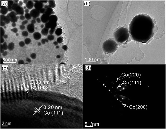
Fig. 2 shows the as-synthesized Co@BN nanoparticles with a core–shell structure. For the sample 13.6 wt% Co@BN, it has a particle size of ca. 100–200 nm in diameter and a shell of 30–50 nm in thickness (Fig. 2a and b). Moreover, the high-resolution TEM (HRTEM) image (Fig. 2c) displays the lattice fringes corresponding to the (002) plane of h-BN and the (111) plane of cubic metallic cobalt, respectively. Fig. 2d presents the selected-area electron diffraction (SAED) patterns indexed to (111), (200), and (220) of cubic cobalt, which is in agreement with the XRD results. Meanwhile, Fig. 2d also demonstrates that the as-formed cobalt core is single crystalline.54 The nanoflake shell shows a polycrystalline SAED pattern corresponding to the hexagonal BN phase.55
The magnetization curve displays that Co@BN nanoparticles are superparamagnetic56,57 at 300 K (Fig. S2a†). The saturation magnetization (Ms) value was determined to be 21.27 emu g−1 from the hysteresis loops of Co@BN. We also found that Co@BN nanoparticles can be easily dispersed in a post-reaction solution (see catalytic activity test for details) and quickly collected by a magnet (Fig. S2b†), which is beneficial for its recovery and reuse for application in heterogeneous catalysis.
3.2 Catalytic activity of Co@BN
The catalytic performance of the as-prepared samples was evaluated through catalytic hydrogenation of nitroarenes (e.g. 4-nitrophenol). The reduction of 4-nitrophenol by excess NaBH4 follows the equation under alkaline conditions indicated as follows:
 | (1) |
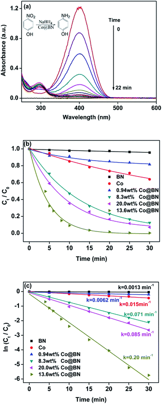
This reaction can be easily monitored by UV-visible spectroscopy. Normally, 4-nitrophenol has a typical absorption peak at 317 nm (Fig. S3†). However, after adding NaBH4 solution, a red shift of the maximum absorption peak occurs from 317 nm to 400 nm immediately and its color accordingly altered from light yellow to deep yellow, which is attributed to the formation of 4-nitrophenolate ions under alkaline conditions.58 Therefore, we monitored the concentration of 4-nitrophenol through the absorbance at 400 nm. Interestingly, when h-BN was mixed with 4-nitrophenol, the absorbance at 400 nm had a slight increase, suggesting that the support h-BN can function as a weak base to ionize a part of 4-nitrophenol. Fig. 3a shows the time course of catalytic reduction of 4-nitrophenol by NaBH4 over 13.63 wt% Co@BN composites. Decrease in the absorbance of the peak at 400 nm with reaction time means the conversion of 4-nitrophenol. Moreover, two isosbestic points are observed at 277 nm and 312 nm, suggesting that the 4-nitrophenol were quickly converted to 4-aminophenol without any byproducts.59 Complete conversion of 4-nitrophenol to 4-aminophenol was achieved within 22 min. The yield and selectivity were 96% and 99%, respectively. The total turnover number (TON) of 13.63 wt% Co@BN was 5, which is higher than some cobalt-based catalysts reported in the literature (Table S1†). These results suggest that Co@BN nanoparticles exhibited a good catalytic activity.
To further explore the catalytic behavior of the Co@BN samples, comparative experiments and kinetics on the conversion of 4-nitrophenol to 4-aminophenol were investigated. According to Lambert–Beer's law, the ratio of the concentration of 4-nitrophenol at any time (Ct) and the initial concentration of 4-nitrophenol (C0), namely Ct/C0, can be determined by the ratio of the corresponding absorbance (At/A0). Fig. 3b describes the time course of Ct/C0 for the as-prepared catalysts, which reflects the catalytic activity of the catalysts used. 0.94 wt% Co@BN, h-BN and bare cobalt were only slightly active with a slow reduction of 4-nitrophenol. Obviously, 13.6 wt% Co@BN possesses the highest catalytic activity among the samples. Moreover, since the concentration of NaBH4 is generally much higher than that of 4-nitrophenol ([NaBH4]/[4-NP] = 205![[thin space (1/6-em)]](https://www.rsc.org/images/entities/char_2009.gif) :
:![[thin space (1/6-em)]](https://www.rsc.org/images/entities/char_2009.gif) 1), this reduction reaction (eqn (1)) can be considered as a pseudo-first-order reaction.59 Fig. 3c represents plots of ln(Ct/C0) versus relevant reaction time for the catalysts. As can be seen, the linear relationship between ln(Ct/C0) and the corresponding reaction time confirms that pseudo-first-order kinetics is available for this reaction. According to the first order kinetic equation: ln(Ct/C0) = −kt, the rate constant k can be directly achieved by using absolute values of the slope of the linear plots. It is clear that among the samples, the catalyst 13.6 wt% Co@BN has the highest rate constant 0.20 min−1, and was chosen as a model catalyst in this study.
1), this reduction reaction (eqn (1)) can be considered as a pseudo-first-order reaction.59 Fig. 3c represents plots of ln(Ct/C0) versus relevant reaction time for the catalysts. As can be seen, the linear relationship between ln(Ct/C0) and the corresponding reaction time confirms that pseudo-first-order kinetics is available for this reaction. According to the first order kinetic equation: ln(Ct/C0) = −kt, the rate constant k can be directly achieved by using absolute values of the slope of the linear plots. It is clear that among the samples, the catalyst 13.6 wt% Co@BN has the highest rate constant 0.20 min−1, and was chosen as a model catalyst in this study.
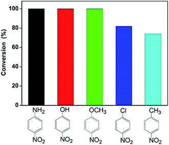
Furthermore, we also investigated catalytic reduction of other nitroarenes including 4-nitroaniline, 4-nitrochlorobenzene, 4-nitromethylbenzene and 4-nitroanisole under the same reaction condition. Fig. 4 gives conversion of these nitroarenes within 30 min in the presence of excess NaBH4 using the catalyst 13.6 wt% Co@BN. The conversion reaches about 100% for 4-nitroaniline, 4-nitrophenol and 4-nitroanisole, while about 82 and 74% for 4-nitrochlorobenzene and 4-nitromethylbenzene, respectively. This is likely due to substituent effect from different functional groups (e.g. hydroxyl, methyl) for nitroarenes.60–62 Among these reactants, nitroarenes with electron-donating groups (e.g. p-OH, p-NH2, p-OCH3) appears to be more easily reduced than those with electron-withdrawing groups (e.g. p-Cl),60–62 while for hydrophobic 4-methylnitrobenzene poor water-solubility restricts its reaction activity.61 The results also suggest that the Co@BN nanocatalysts possess excellent catalytic activity for the hydrogenation of nitroarenes with different substituent groups.
3.3 Kinetic study
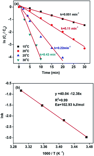
For this reduction reaction (eqn (1)), the standard reduction potential for 4-NP/4-AP and H3BO3/BH4− are −0.76 and −1.33 V versus normal hydrogen electrode (NHE), respectively.58,63 That is to say, this reaction is a thermodynamically feasible process as indicated by eqn (1). Nevertheless, it is difficult for this reaction to spontaneously proceed without catalysts (Fig. S4†) due to a high activation energy.58 Fig. 5 presents kinetic study on the reduction of 4-nitrophenol to 4-aminophenol catalyzed by 13.6 wt% Co@BN at various temperatures: 15, 20, 25 and 30 °C. The relevant linear relationships between ln(Ct/C0) and the corresponding reaction time are shown in Fig. 5a. It is clear that the reaction rate is quite sensitive to temperature and the value of rate constant k increases with the temperature conducted. In addition, according to the Arrhenius equation: , the activation energy (Ea) can be obtained from the slope on the basis of the linear fitting of ln
![[thin space (1/6-em)]](https://www.rsc.org/images/entities/char_2009.gif) k versus 1000/T. The activation energy of the reaction catalyzed by 13.6 wt% Co@BN was determined to be 102.93 kJ mol−1 from the Arrhenius plot (Fig. 5b).
k versus 1000/T. The activation energy of the reaction catalyzed by 13.6 wt% Co@BN was determined to be 102.93 kJ mol−1 from the Arrhenius plot (Fig. 5b).
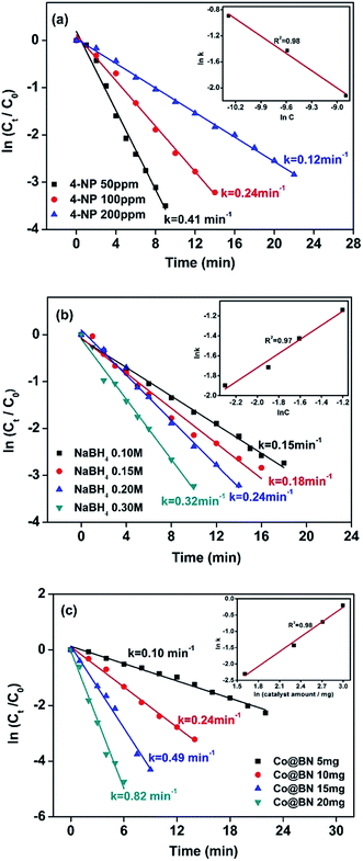
As seen in eqn (1), the concentration of sodium hydroxide and 4-nitrophenol and catalyst amount play an important role on the catalytic reaction. Fig. 6a shows the effect of 4-nitrophenol at initial concentrations of 50, 100 and 200 ppm on reaction kinetics, while keeping the NaBH4 concentration constant at 0.2 M and the amount of catalyst at 10 mg. The rate constant k was found to decrease with increasing the concentration of 4-nitrophenol. This kind of phenomenon seems abnormal, Xia et al. explained that a high concentration of 4-nitrophenol may cover almost the entire surface of the catalyst, which limits electron transfer from NaBH4 to 4-nitrophenol and thus hinders the catalytic action of NaBH4.64 The slope of the line given in the insert of Fig. 6a, 0.98 ≈ 1, suggests that the reaction is first order with respect to the 4-nitrophenol concentration.65,66 Fig. 6b presents the effect of the NaBH4 concentration (0.1, 0.15, 0.2 and 0.3 M) on the reduction of 4-nitrophenol. 4-Aminophenol generation rate is improved with the increment of the concentration of NaBH4. The plot of ln![[thin space (1/6-em)]](https://www.rsc.org/images/entities/char_2009.gif) k vs. ln[NaBH4] gives a straight line with a slope of 0.97 ≈ 1, meaning that the catalytic reaction is first order with respect to the NaBH4 concentration (Fig. 6b inset). Fig. 6c reveals an effect of catalyst dosage on 4-aminophenol generation rate. We can see that the 4-aminophenol generation rate increases with the amount of catalyst. Moreover, the slope of the plot of ln
k vs. ln[NaBH4] gives a straight line with a slope of 0.97 ≈ 1, meaning that the catalytic reaction is first order with respect to the NaBH4 concentration (Fig. 6b inset). Fig. 6c reveals an effect of catalyst dosage on 4-aminophenol generation rate. We can see that the 4-aminophenol generation rate increases with the amount of catalyst. Moreover, the slope of the plot of ln![[thin space (1/6-em)]](https://www.rsc.org/images/entities/char_2009.gif) k vs. ln(catalyst amount) is 0.98, which is approximately equal to 1 (Fig. 6c insert). Therefore, the reduction of 4-NP is first order with respect to the amount of Co@BN catalyst.
k vs. ln(catalyst amount) is 0.98, which is approximately equal to 1 (Fig. 6c insert). Therefore, the reduction of 4-NP is first order with respect to the amount of Co@BN catalyst.
3.4 Stability and recycle of Co@BN
Stability or recycling ability is of great importance to the performance of catalysts. The recycling experiment for 13.6 wt% Co@BN was carried out by repeating the reduction process for five cycles (Fig. 7). Successive UV-vis spectra for the reduction reaction of 4-nitrophenol in each catalysis recycle given in Fig. S5.† Furthermore, we have detected the load of Co on the recycled catalyst by inductive coupled plasma emission spectrometer (Table S2†). A slight weight loss in cobalt load in Co@BN catalysts ranges from 13.6% (before catalysis) and 11.5% (after five catalysis cycles). Considering detecting deviation (∼2%) for this measurement, we believe that Co nanostructures are relatively stable during the reduction reactions. The recycle experiments showed that the as-prepared Co@BN nanocatalyst has an excellent catalytic stability. Moreover, by comparing the XRD patterns of the catalyst before and after the reaction (Fig. S6†), there is no obvious change in diffraction peaks, confirming the structure stability of the catalyst during the reaction.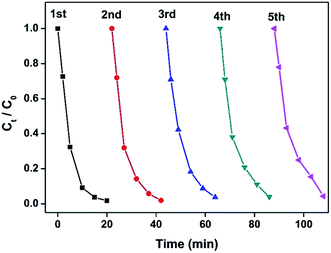 | ||
| Fig. 7 Plots of Ct/C0 versus time for the reduction of 4-NP catalyzed by the as-prepared 13.6 wt% Co@BN catalyst ([4-NP] = 100 ppm). The catalyst was repeatedly used for five cycles. | ||
3.5 Adsorption of h-BN
High surface area, thermal and chemical stability makes h-BN become an ideal candidate as an absorbent material,30 which is helpful for heterogeneous catalysis. In this regard, the specific surface area and pore size distribution of 13.6 wt% Co@BN were analyzed using N2 adsorption and desorption isotherms, respectively (Fig. S7†). The Co@BN sample displayed typical type IV adsorption isotherms with an H3-type hysteresis loop.67 Co@BN had BET-specific surface areas of approximately 46.6 m2 g−1. The pore size distribution (calculated via the BJH method) shows that the pore size of Co@BN is centered at around 13.2 nm (Fig. S7b†). This suggests a mesoporous structure characteristic of the Co@BN. Meanwhile, the mesoporous size distribution is a relatively wide which is beneficial for improving the adsorption of the reactants. Meanwhile, the absorption performance of BN on 4-nitrophenol solutions with consecration of 50, 100 and 200 ppm were explored. Fig. S8a† describes the absorbance change of 4-nitrophenol (100 ppm) at 317 nm over time in the presence of h-BN. After dispersing 10 mg of h-BN powder into 4-nitrophenol solutions with stirring, the absorbance at 317 nm quickly decreased to a much lower constant value within 2 min. Moreover, for the 4-nitrophenol solutions of 50 ppm and 200 ppm, the absorption approaches saturation in nearly 3 min and 1 min, respectively (Fig. S8b and c†). Through quick absorption of 4-nitrophenol, a high local concentration of 4-nitrophenol occurs on the surface of h-BN and at the vicinity of the catalyst. This is beneficial to accelerate the reaction rate.3.6 Approaching to the mechanism
To get more insights into the reaction process, the EPR experiment was conducted at room temperature using a spin trapper DMPO. Results obtained from spin trapping experiments are displayed in Fig. S9.† It is clear that spectra (b) and (c) originate from the formation of H˙ radical adducts (DMPO-H, aN = 16.6 G, aH = 22.5 G)68 for the solution containing and (b) DMPO, NaBH4 and 4-nitrophenol and (c) DMPO and NaBH4, respectively. When adding the catalyst in the solution containing DMPO, NaBH4 and 4-nitrophenol, EPR spectrum becomes more complicated (spectrum (a)). By analyzing spectrum (a), we found that not only H-DMPO adducts but also HOO˙ free radicals formed in the process of catalytic reaction.69 The formation of HOO˙ may be due to a large amount of H˙ radicals rapidly produced over the catalyst and trapped by trace amount oxygen in the solution. Besides, control experiments revealed that no H˙ adduct formed for 4-nitrophenol or catalysts with and without DMPO (Fig. S9d–h†). According to the EPR results, since the catalytic reaction takes place on the surface of metal, the formation of the hydrogen spin adducts most likely come from the abstraction of hydrogen from the cobalt surface by a spin trap. This is similar to the formation of Au–H species during the alcohol oxidation.69 These results thus strongly suggest intermediate formation of Co–H species during 4-nitrophenol reduction.The kinetics of this reaction has been modeled on the basis of a Langmuir–Hinshelwood mechanism, namely, both reactants need to be adsorbed on the surface prior to reaction.70 It means the adsorption of reactants is of great importance for the reaction. In this work, the strong absorption of 4-nitrophenol by h-BN improves local concentration of reactants around the catalyst, which is favorable for the catalytic reaction. This can be regarded as a synergistic effect of the shell h-BN and the core cobalt. On the basis of our results, we propose the following possible mechanism for Co@BN catalyzing 4-nitrophenol reduction in the presence of NaBH4 (Fig. 8a). Firstly, BH4− and 4-nitrophenol are adsorbed on the catalysts surface. Then the adsorbed BH4− transfers electrons to Co NPs to form Co–H species. Secondly, the electrons are transferred from Co–H species to the adsorbed 4-nitrophenol and thus reduction of 4-nitrophenol to 4-aminophenol proceeds. According to the possible reaction pathways for the catalytic reduction of aromatic nitro compounds based on Haber's model,71,72 a direct hydrogenation route for 4-nitrophenol could be schematically presented in Fig. 8b.64 This is a six-electron transfer process.73 Finally, 4-aminophenol is desorbed from the surface of Co@BN catalysts and dispersed in the reaction solution. To gain further insight into the detailed mechanism, however, more experimental and theoretical work is needed.
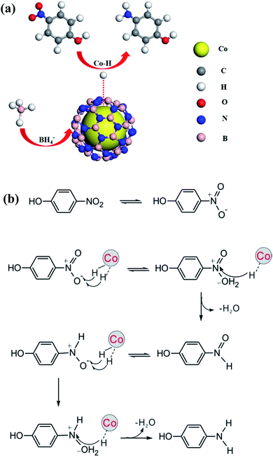 | ||
| Fig. 8 (a) Proposed mechanism and (b) possible reaction pathways for the 4-NP reduction by NaBH4 in the presence of a Co@BN catalyst. | ||
4. Conclusions
In this study, we present a facile one-step synthesis of Co@BN core–shell nanostructures through high-temperature calcination of boron oxide, urea and cobalt(II) nitrate. The as-prepared Co@BN nanoparticles exhibited high chemical stability and good magnetic properties and were used as catalysts for the reduction of nitroarenes. We found that Co@BN nanoparticles showed high catalytic performance, durable stability and magnetic recyclability for hydrogenation of nitroarenes to aminoarenes in the presence of excess NaBH4. We proved that the sample 13.6 wt% Co@BN exhibited the excellent catalytic activity in hydrogenation of 4-nitrophenol, 4-nitroaniline, 4-nitrochlorobenzene, 4-nitromethylbenzene and 4-nitroanisole. In addition, a significant synergistic effect of the support h-BN was observed by effectively adsorbing the reactant nitroaromatics, leading to an obvious increase in its surface concentration. Furthermore, we also demonstrated that the catalytic reaction is first order with respect to 4-nitrophenol concentration, sodium borohydride concentration and catalyst amount. The activation energy for reduction of 4-nitrophenol for 13.6 wt% Co@BN was determined to be 102.93 kJ mol−1. This work gives evidence that Co@BN core–shell nanoparticles possess easy recyclability, chemical stability and excellent catalytic activity for surface catalytic reaction, and the design concept used in the Co@BN core–shell catalyst can be extended to other metal/nonmetal nanocomposites.Conflict of interest
The authors declare no competing financial interest.Acknowledgements
This work was supported by the National Natural Science Foundation of China (No. U1662112, 21273038, 21543002 and 11305091).References
- Y. Bao, H. Calderon and K. M. Krishnan, J. Phys. Chem. C, 2007, 111, 1941–1944 CAS.
- O. Margeat, C. Amiens, B. Chaudret, P. Lecante and R. E. Benfield, Chem. Mater., 2005, 17, 107–111 CrossRef CAS.
- L. Zhou, Y. Guo and K. Hideo, AIChE J., 2014, 60, 2907–2917 CrossRef CAS.
- F. Hebrard and P. Kalck, Chem. Rev., 2009, 109, 4272–4282 CrossRef CAS PubMed.
- G. Cahiez and A. Moyeux, Chem. Rev., 2010, 110, 1435–1462 CrossRef CAS PubMed.
- S. Gao, Y. Lin, X. Jiao, Y. Sun, Q. Luo, W. Zhang, D. Li, J. Yang and Y. Xie, Nature, 2016, 529, 68–71 CrossRef CAS PubMed.
- A. P. Unnarkat, T. Sridhar, H. Wang, S. Mahajani and A. K. Suresh, AIChE J., 2016, 62, 4384–4402 CrossRef CAS.
- H. Wang, Z. Dong and C. Na, ACS Sustainable Chem. Eng., 2013, 1, 746–752 CrossRef CAS.
- Y. Niu and R. M. Crooks, C. R. Chim., 2003, 6, 1049–1059 CrossRef CAS.
- C. J. Zhong and M. M. Maye, Adv. Mater., 2001, 13, 1507–1511 CrossRef CAS.
- E. E. Carpenter, C. Sangregorio and C. J. O'Connor, IEEE Trans. Magn., 1999, 35, 3496–3498 CrossRef CAS.
- N. S. Sobal, U. Ebels, H. Möhwald and M. Giersig, J. Phys. Chem. B, 2003, 107, 7351–7354 CrossRef CAS.
- N. S. Sobal, M. Hilgendorff, H. Möhwald and M. Giersig, Nano Lett., 2002, 2, 621–624 CrossRef CAS.
- M. A. Hines and P. Guyot-Sionnest, J. Phys. Chem. C, 1996, 100, 468–471 CrossRef CAS.
- B. O. Dabbousi, J. Rodriguez-Viejo, F. V. Mikulec, J. R. Heine, H. Mattoussi, R. Ober, K. F. Jensen and M. G. Bawendi, J. Phys. Chem. B, 1997, 101, 9463–9475 CrossRef CAS.
- X. Peng, M. C. Schlamp, A. V. Kadavanich and A. P. Alivisatos, J. Am. Chem. Soc., 1997, 119, 7019–7029 CrossRef CAS.
- O. I. Mićić, B. B. Smith and A. J. Nozik, J. Phys. Chem. B, 2000, 104, 12149–12156 CrossRef.
- Y. W. Cao and U. Banin, Angew. Chem., Int. Ed., 1999, 38, 3692–3694 CrossRef CAS PubMed.
- M. A. Correa-Duarte, M. Giersig and L. M. Liz-Marzan, Chem. Phys. Lett., 1998, 286, 497–501 CrossRef CAS.
- M. Danek, K. F. Jensen, C. B. Murray and M. G. Bawendi, Chem. Mater., 1996, 8, 173–180 CrossRef CAS.
- C. W. Chen, M. Q. Chen, T. Serizawa and M. Akashi, Adv. Mater., 1998, 10, 1122–1126 CrossRef CAS.
- S. Phadtare, A. Kumar, V. P. Vinod, C. Dash, D. V. Palakar, M. Rao, P. G. Shukla, S. Sivaram and M. Sastry, Chem. Mater., 2003, 15, 1944–1949 CrossRef CAS.
- S. H. Joo, J. Y. Park, C. K. Tsung, Y. Yamada, P. Yang and G. A. Somorjai, Nat. Mater., 2009, 8, 126–131 CrossRef CAS PubMed.
- H. G. Boyen, G. Kastle, K. Zurn, T. Herzog, F. Weigl, P. Ziemann, O. Mayer, C. Jerome, M. Moller, J. P. Spatz, M. G. Garnier and P. Oelhafen, Adv. Funct. Mater., 2003, 13, 359–364 CrossRef CAS.
- L. Hang, Y. Zhao, H. Zhang, G. Liu, W. Cai, Y. Li and L. Qu, Acta Mater., 2016, 105, 59–67 CrossRef CAS.
- A. Lopez-Bezanilla, J. Huang, H. Terrones and B. G. Sumpter, Nano Lett., 2011, 11, 3267–3273 CrossRef CAS PubMed.
- C. Huang, Q. liu, W. Fan and X. Qiu, Sci. Rep., 2015, 5, 16736 CrossRef CAS PubMed.
- L. Song, L. Ci, H. Lu, P. B. Sorokin, C. Jin, J. Ni, A. G. Kvashnin, D. G. Kvashnin, J. Lou, B. I. Yakobson and P. M. Ajayan, Nano Lett., 2010, 10, 3209–3215 CrossRef CAS PubMed.
- Z. Liu, Y. Gong, W. Zhou, L. Ma, J. Yu, J. C. Idrobo, J. Jung, A. H. MacDonald, R. Vajtai, J. Lou and P. M. Ajayan, Nat. Commun., 2013, 4, 2451 Search PubMed.
- W. Lei, D. Portehault, D. Liu, S. Qin and Y. Chen, Nat. Commun., 2013, 4, 1777 CrossRef PubMed.
- Q. Weng, Y. Ide, X. Wang, X. Wang, C. Zhang, X. Jiang, Y. Xue, P. Dai, K. Komaguchi, Y. Bando and D. Golberg, Nano Energy, 2015, 16, 19–27 CrossRef CAS.
- X. Lv, J. Wang, Z. Yan, D. Jiang and J. Liu, J. Mol. Catal. A: Chem., 2016, 418–419, 146–153 CrossRef CAS.
- M. Wang, M. Li, L. Xu, L. Wang, Z. Ju, G. Li and Y. Qian, Catal. Sci. Technol., 2011, 1, 1159 CAS.
- G. Yadav and P. Goel, Clean Technol. Environ. Policy, 2002, 4, 227–234 CrossRef CAS.
- G. D. Yadav, Y. B. Jadhav and S. Sengupta, Chem. Eng. Sci., 2003, 58, 2681–2689 CrossRef CAS.
- Y. Zhang, H. P. Tran, I. Hussain, Y. Zhong and S. Huang, Chem. Eng. J., 2015, 279, 396–401 CrossRef CAS.
- Y. Yuan, H. Tao, J. Fan and L. Ma, Chem. Eng. J., 2015, 268, 38–46 CrossRef CAS.
- Y. Q. Zhang, X. Z. Du and W. L. Huang, Chin. Chem. Lett., 2011, 22, 358–361 CrossRef CAS.
- T. R. Mandlimath and B. Gopal, J. Mol. Catal. A: Chem., 2011, 350, 9–15 CrossRef CAS.
- K. L. Wu, X. W. Wei, X. M. Zhou, D. H. Wu, X. W. Liu, Y. Ye and Q. Wang, J. Phys. Chem. C, 2011, 115, 16268–16274 CAS.
- P. Deka, R. C. Deka and P. Bharali, New J. Chem., 2014, 38, 1789 RSC.
- J. Li, C. Y. Liu and Y. Liu, J. Mater. Chem., 2012, 22, 8426 RSC.
- B. A. Donlon, E. Razo-Flores, J. A. Field and G. Lettinga, Appl. Environ. Microbiol., 1995, 61, 3889–3893 CAS.
- M. Guo, J. He, Y. Li, S. Ma and X. Sun, J. Hazard. Mater., 2016, 310, 89–97 CrossRef CAS PubMed.
- S. M. Alshehri, T. Almuqati, N. Almuqati, E. Al-Farraj, N. Alhokbany and T. Ahamad, Carbohydr. Polym., 2016, 151, 135–143 CrossRef CAS PubMed.
- C. Huang, W. Ye, Q. Liu and X. Qiu, ACS Appl. Mater. Interfaces, 2014, 6, 14469–14476 CAS.
- X. Qiu, Q. Liu, M. Song and C. Huang, J. Colloid Interface Sci., 2016, 477, 131–137 CrossRef CAS PubMed.
- Y. Li, W. Qiu, F. Qin, H. Fang, V. G. Hadjiev, D. Litvinov and J. Bao, J. Phys. Chem. C, 2016, 120, 4511–4516 CAS.
- V. Gandhi, R. Ganesan, H. H. Abdulrahman Syedahamed and M. Thaiyan, J. Phys. Chem. C, 2014, 118, 9715–9725 CAS.
- Q. Yang, Y. Z. Chen, Z. U. Wang, Q. Xu and H. L. Jiang, Chem. Commun., 2015, 51, 10419–10422 RSC.
- X. Chen, J. Chang, H. Yan and D. Xia, J. Phys. Chem. C, 2016, 120, 28912–28916 CAS.
- S. Wunder, F. Polzer, Y. Lu, Y. Mei and M. Ballauff, J. Phys. Chem. C, 2010, 114, 8814–8820 CAS.
- D. T. Dam and J. M. Lee, ACS Appl. Mater. Interfaces, 2014, 6, 20729–20737 CAS.
- L. Gao, R. Li, X. Sui, R. Li, C. Chen and Q. Chen, Environ. Sci. Technol., 2014, 48, 10191–10197 CrossRef CAS PubMed.
- X. Xia, J. Tu, Y. Zhang, X. Wang, C. Gu, X. Zhao and H. Fan, ACS Nano, 2012, 6, 5531–5538 CrossRef CAS PubMed.
- K. Y. Andrew Lin and H. A. Chang, Chem. Eng. J., 2016, 296, 243–251 CrossRef.
- L. Zhang, W. Wang, L. Zhou, M. Shang and S. Sun, Appl. Catal., B, 2009, 90, 458–462 CrossRef CAS.
- E. Seo, J. Kim, Y. Hong, Y. S. Kim, D. Lee and B.-S. Kim, J. Phys. Chem. C, 2013, 117, 11686–11693 CAS.
- M. Nemanashi and R. Meijboom, Catal. Commun., 2016, 83, 53–57 CrossRef CAS.
- A. Noschese, A. Buonerba, P. Canton, S. Milione, C. Capacchione and A. Grassi, J. Catal., 2016, 340, 30–40 CrossRef CAS.
- H. S. Shin and S. Huh, ACS Appl. Mater. Interfaces, 2012, 4, 6324–6331 CAS.
- A. A. Vernekar, S. Patil, C. Bhat and S. G. Tilve, RSC Adv., 2013, 3, 13243 RSC.
- T. Yang, H. Y. Zou and C. Z. Huang, ACS Appl. Mater. Interfaces, 2015, 7, 15447–15457 CAS.
- F. Xia, X. Xu, X. Li, L. Zhang, L. Zhang, H. Qiu, W. Wang, Y. Liu and J. Gao, Ind. Eng. Chem. Res., 2014, 53, 10576–10582 CrossRef CAS.
- D. Sun, V. Mazumder, Ö. Metin and S. Sun, ACS Catal., 2012, 2, 1290–1295 CrossRef CAS.
- E. K. Abo-Hamed, T. Pennycook, Y. Vaynzof, C. Toprakcioglu, A. Koutsioubas and O. A. Scherman, Small, 2014, 10, 3145–3152 CrossRef CAS PubMed.
- H. Li, F. Yue, C. Yang, P. Xue, N. Li, Y. Zhang and J. Wang, CrystEngComm, 2017, 19, 64–71 RSC.
- K. Makino, M. M. Mossoba and P. Riesz, J. Phys. Chem., 1983, 87, 1369–1377 CrossRef CAS.
- M. Conte, H. Miyamura, S. Kobayashi and V. Chechik, J. Am. Chem. Soc., 2009, 131, 7189–7196 CrossRef CAS PubMed.
- S. Wunder, F. Polzer, Y. Lu, Y. Mei and M. Ballauff, J. Phys. Chem. C, 2010, 114, 8814–8820 CAS.
- A. Corma, P. Concepcion and P. Serna, Angew. Chem., 2007, 46, 7266–7269 CrossRef CAS PubMed.
- F. Haber, Z. Elektrochem., 1898, 22, 506 Search PubMed.
- S. Saha, A. Pal, S. Kundu, S. Basu and T. Pal, Langmuir, 2010, 26, 2885–2893 CrossRef CAS PubMed.
Footnote |
| † Electronic supplementary information (ESI) available. See DOI: 10.1039/c7ra04907b |
| This journal is © The Royal Society of Chemistry 2017 |

