 Open Access Article
Solution-processed multifunctional transparent conductive films based on long silver nanowires/polyimide structure with highly thermostable and antibacterial properties†
Yan Yua,
Wenfeng Shen *a,
Fan Lib,
Xingzhong Fanga,
Hong Duanb,
Feng Xua,
Yonghua Xiongb,
Wei Xu
 a and
Weijie Song*a
aNingbo Institute of Material Technology and Engineering, Chinese Academy of Sciences, Ningbo, Zhejiang 315201, China. E-mail: wfshen@nimte.ac.cn; weijiesong@nimte.ac.cn
bState Key Laboratory of Food Science and Technology, Nanchang University, Nanchang, Jiangxi 330047, China
First published on 31st May 2017
Abstract
Flexible transparent films that have excellent photoelectric properties, mechanical and thermal stability, and antibacterial properties, are highly desirable for applications in flexible and wearable electronics. Multifunctional transparent conductive films (TCFs) with long silver nanowires (AgNWs, average length = 80 μm and average diameter = 88 nm)/transparent polyimide (PI) structures which were fabricated by using a facile, scalable, environmentally-friendly, and full-solution process, can satisfy all the requirements above. The AgNW/PI composite films show excellent opto-electrical properties (e.g., 7.5 ohm sq−1, at 81.1% transmittance) and mechanical flexibility across a wide temperature range, from room temperature to 300 °C. The AgNW networks were embedded into the transparent PI film surface, which could decrease the surface roughness (Rrms < 2.0 nm), and enhance the composite films' resistance to peeling, fracture, and oxidation, which expands the range of TCF applications considerably. Additionally, in exploring promising applications, the function of the transparent heater and the antibacterial properties of the composite films were also studied. These characteristics make the composite films excellent candidates for substrates for flexible and wearable electronic devices.
1. Introduction
Indium tin oxide (ITO) is commonly used as a transparent conductive film (TCF) due to its high electrical conductivity and optical transparency.1–3 However, the brittle ceramic structure, poor compatibility with organic materials, and the growing cost of indium seriously limit the use of ITO in TCFs, especially in emerging flexible electronics and large-area applications.4–7 Therefore, there are various ITO alternative materials used to prepare flexible TCFs, such as new oxide films,8 conducting polymers,9 carbon nanotubes,10,11 graphene-based films,12 silver nanowires (AgNWs),13–15 and hybrids of these.16–18 Among them, AgNW-based TCFs have generated great interest owing to their excellent electrical conductivity, high transparency, and suitable mechanical flexibility.19 Furthermore, AgNWs usually were dispersed in organic solvents which were easy to deposit onto various different transparent substrates, such as glass, polyethylene, polyethylene glycol terephthalate and polycarbonates.20–23 Therefore, AgNW networks on both glass and plastic have been used at a research and commercial scale in a variety of applications.However, AgNW films, while promising, still suffer from several inherent limitations, including poor adhesion to the substrate, large surface roughness, and thermal instability at temperatures above 300 °C, which severely restrict their applicability.24,25 We recently reported on conductive films on polyimide (PI) substrates with an aluminum-doped zinc oxide (AZO)/AgNW/AZO structure to overcome the above-mentioned limitations.26 However, the fabrication process of the hybrid films is complicated and the photoelectric properties (e.g., 8.6 ohm sq−1, at 74.4% transparence) is less than desirable. We also had reported short AgNWs/PI films as transparent heater, in which the performance of the hybrid TCFs cannot be considered to be fully acceptable due to the AgNWs with low aspect ratio (<250).27 It is still a big challenge to fabricate highly conductive and air-stable AgNW-based TCFs for flexible and wearable electronics.
This work is a continuation of our previous work.26,27 Herein, we report a very facile modified polyol method to synthesize long AgNWs with high aspect ratio (>900) in large quantities. Furthermore, we present a TCF with excellent photoelectric properties, and with mechanical and thermal stability, by embedding long silver nanowires into PI films using a facile, scalable, environmentally friendly, and full-solution process. The AgNW/PI film had a sheet resistance of 7.5 ohm sq−1 with a transmittance of 81.1% at 550 nm (note: excluding the PI substrate, the transmittance of AgNW network is 89.5%). We also report a facile modified polyol method to synthesize long AgNWs with high aspect ratio (>900) in large quantities. Additionally, as examples of promising applications, the performance of the AgNW/PI composite films as transparent heater and their antibacterial activities were also demonstrated.
2. Experimental procedures
2.1. Materials
The reagents used in this study were silver nitrate (AgNO3), poly(vinylpyrrolidone) (PVP), ferric chloride (FeCl3), ethylene glycol (EG), acetone, ethanol and N,N-dimethylacetamide (DMAc). All reagents were of analytical grade and purchased from Sinopharm Chemical Reagent Co., Ltd. All chemicals were used as received without further purification.2.2. Synthesis of silver nanowires
Usual AgNWs are limited to lengths shorter than 40 μm, and the yield is less than 1 g for each synthesis process. We developed a modified polyol method to synthesize longer AgNWs in larger quantities. First, 3 g of PVP (Mw = 360![[thin space (1/6-em)]](https://www.rsc.org/images/entities/char_2009.gif) 000), 3 g of PVP (Mw = 58
000), 3 g of PVP (Mw = 58![[thin space (1/6-em)]](https://www.rsc.org/images/entities/char_2009.gif) 000) and 1 L of EG were added in a three-neck flask at room temperature with magnetic stirring to make them dissolve completely. Then, 13.2 g of AgNO3 was added to the flask. Keeping it magnetic stirring for 10 min, a transparent and uniform solution was obtained. A FeCl3 solution (200 μL 0.1 M in EG) was then added to the flask and stirred for 3 minutes. The mixture was then immediately moved into an oil bath pan which had been preheated at 135 °C to grow AgNWs for 3.5 hours until the reaction was finished. During the reaction process, the mixture color changed from light yellow (Fig. S1(a)†), brown (Fig. S1(b)†), and finally gray (Fig. S1(c)†), indicating the formation of AgNWs. Acetone was added into the resulted solution, which was then centrifuged 3 times at 1500 rpm to remove EG, PVP, and other impurities. After cleaning, the AgNWs were suspended in ethanol at a concentration of 28 mg mL−1 for future use (Fig. S1(d)†).
000) and 1 L of EG were added in a three-neck flask at room temperature with magnetic stirring to make them dissolve completely. Then, 13.2 g of AgNO3 was added to the flask. Keeping it magnetic stirring for 10 min, a transparent and uniform solution was obtained. A FeCl3 solution (200 μL 0.1 M in EG) was then added to the flask and stirred for 3 minutes. The mixture was then immediately moved into an oil bath pan which had been preheated at 135 °C to grow AgNWs for 3.5 hours until the reaction was finished. During the reaction process, the mixture color changed from light yellow (Fig. S1(a)†), brown (Fig. S1(b)†), and finally gray (Fig. S1(c)†), indicating the formation of AgNWs. Acetone was added into the resulted solution, which was then centrifuged 3 times at 1500 rpm to remove EG, PVP, and other impurities. After cleaning, the AgNWs were suspended in ethanol at a concentration of 28 mg mL−1 for future use (Fig. S1(d)†).
2.3. Fabrication of the AgNW/PI TCFs
The PI powders were first prepared according to our previous studies.27 The PI powders were dissolved in DMAc solution with a weight percent of 10%. After stirred for 10 minutes, the homogenous PI solution was obtained. Fig. 1 schematically illustrates the fabrication of the AgNW/PI composite films. The AgNW dispersion was rod-coated on glass substrates (10 cm × 10 cm) with different coating cycles and then dried on a hot plate for 10 minutes at 80 °C. 1 mL AgNW dispersion solution (∼0.006 M) was used for each rod-coating cycle. With increasing AgNW dispersion rod-coated cycles, the value of AgNW areal mass densities of the TCFs is increased. Next, the transparent PI precursor solution was cast on the AgNW networks to form a homogenous solution layer which then was placed in an oven at 80 °C for 2 hours, to evaporate most of the solvent, and continues to heat at 100, 150, and 200 °C for 60 minutes at each temperature. After the heating, the resultant AgNW/PI TCFs with different AgNW areal mass density were peeled off and cut into various sample sizes. There are four samples had been used in this study. Sample A was pure PI films. Sample B, C and D were prepared by rod-coating AgNW dispersion 2, 3 and 7 cycles with the above-mentioned method, respectively. One thing should be noted, certain amount of AgNW dispersion would be wasted during the process of rod-coating. So, the digital multimeter should be used to estimate the sheet resistance of the AgNWs network for each AgNW rod-coating cycle. The thickness of the final AgNW/PI films is approximately 50 μm.2.4. Characterization
The surface morphologies of AgNW/PI TCFs were examined with a scanning electron microscopy (SEM, Hitachi S-4800). The surface roughness of AgNW/PI TCFs was observed with an atomic force microscope (AFM, Veeco Dimension 3100V). The optical transmittances of the transparent PI film and AgNW/PI TCF were obtained at room temperature with an ultraviolet-visible spectrophotometer (Perkin-Elmer, Lambda 950, USA) with an integrating sphere. The sheet resistance of AgNW/PI TCF was measured with a four-point probe system (Napson Corp. Cresbox). The weight of TCFs was measured with thermogravimetric analysis/differential thermal analysis (TG/DTA). The DC voltage was supplied by a power supply to the TCF through a copper contact at the film edge. The temperature of the TCF was measured using an infrared thermometer (Smart Sensor, AR842A). The heat distribution of the TCF was measured by an infrared camera (Fukushima-shi, Fukushima 960-8511). The mechanical stability tests were performed using a lab-made bending test machine. The adhesion test was performed with 3M stock tape.2.5. Antibacterial material synthesis and characterization
The antibacterial ability of the AgNW/PI composite film was assessed against Bacillus cereus (B. cereus) (CMCC (B) 63301) and Escherichia coli (E. coli) (ATCC 51813) using spread plate methods. Briefly, the pure PI and AgNW/PI composite films (2.0 cm × 3.5 cm) were sterilized at 121 °C for 15 min. The two kinds of sterilized films were cut into 4 equal parts, and then put into 5 mL of B. cereus and E. coli solutions containing 0.1% peptone (104 CFU mL−1), respectively. After incubation at 37 °C with shaking at 180 rpm for 8 hours, the viable cell count of each sample was determined by surface plating 0.2 mL with 10![[thin space (1/6-em)]](https://www.rsc.org/images/entities/char_2009.gif) 000 fold dilutions onto LB agar plates. The plates were each incubated at 37 °C for 8 hours (B. cereus and E. coli). The number of CFU mL−1 was obtained by counting the colonies grown on the plates.
000 fold dilutions onto LB agar plates. The plates were each incubated at 37 °C for 8 hours (B. cereus and E. coli). The number of CFU mL−1 was obtained by counting the colonies grown on the plates.
3. Results and discussion
3.1. Microstructure of AgNWs and AgNW/PI TCFs
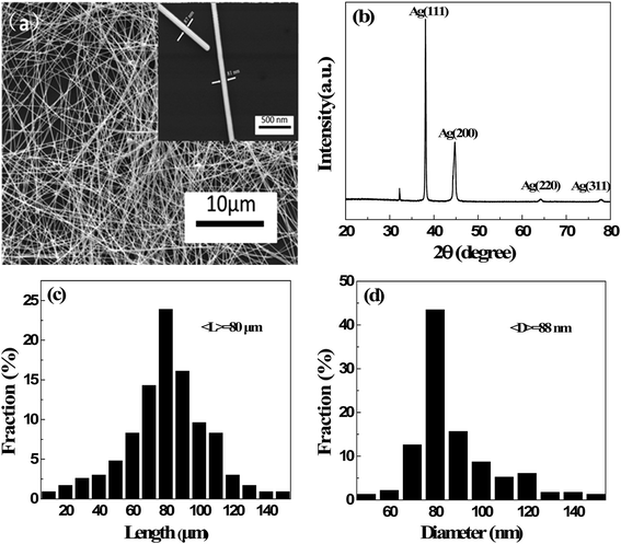
The microstructure of long AgNWs was characterized by SEM and XRD, as shown in Fig. 2(a) and (b). No other morphology of silver nanocrystal was observed. In the XRD pattern of silver nanowires, the three strongest peaks can be observed at 38.2°, 44.4°, and 64.5°. According to the Silver Joint Committee on Powder Diffraction Standards Database (file no. 04-0783), they were attributed to the diffraction of the (111), (200) and (220) crystalline planes of the face-centered structure of silver, respectively. The calculated lattice constant according to the (111) peak is approximately 4.082 Å, which agrees with the standard value of 4.086 Å. Fig. 2(c) and (d) show the distributions of length and diameter by measuring 250 nanowires. The average diameter and length of the prepared silver nanowires were 88 nm and 80 μm, respectively. The aspect ratio of the AgNWs is approximately 910 which was triple improvement than our previous work.27 These results reveal that high aspect ratio AgNWs can be synthesized in large quantities by the modified polyol method.SEM image of AgNW/PI TCF with the sheet resistance of 48.3 ohm sq−1 is shown in Fig. 3(a). The AgNW network has a well-connected wire-to-wire, unlike the forest-like AgNW structure observed in pure AgNW film.27 The AgNW/PI TCF had a smooth surface with a mean surface roughness of 1.96 nm (Fig. 3(b)), which shows the transparent PI solution filled all the voids of the AgNW networks, allowing for the tight integration between silver nanowires and substrate.28
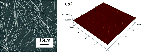 | ||
| Fig. 3 (a) SEM image of AgNW/PI TCF with 48.3 ohm sq−1. (b) Surface roughness of the AgNW/PI TCF with Ra = 1.96 nm. | ||
3.2. Optical and electrical properties of AgNW/PI TCFs
The optical transmittance spectra of the AgNW/PI TCFs with different AgNW densities embedded into the films are shown in Fig. 4, and the values of the thin film optical and electrical parameters are shown in Table 1. The pure PI film (sample A) showed the highest optical transmittance of 90.6% and the lowest haze of 0.7% at 550 nm. With increasing of embedded AgNW densities, the transmittance and the sheet resistance of the TCFs were both decreased, but the haze of the TCFs was increased, which was attributed to more connections between the AgNWs and more light scattering and reflection by the AgNWs.29,30 The AgNW/PI displayed a sheet resistance of 48.3 ohm sq−1 (sample B), 24.5 ohm sq−1 (sample C), and 7.5 ohm sq−1 (sample D) with a transmittance of 86.3%, 82.2%, and 81.1% at 550 nm, respectively. The results indicated that the optical and electrical properties of AgNW/PI TCFs could be optimized by adjusting the AgNW density.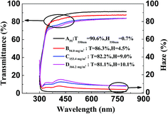 | ||
| Fig. 4 Optical transmittance and haze of the pure PI film and AgNW/PI TCFs with different areal mass densities. | ||
| Sample | amd (mg m−2) | T550 nm (%) | H550 (%) | Rs (ohm sq−1) | Φ (10−3 Ω−1) |
|---|---|---|---|---|---|
| A | — | 90.6 | 0.7 | — | — |
| B | 94.0 | 86.3 | 4.5 | 48.3 | 4.7 |
| C | 153.4 | 82.2 | 9.0 | 24.5 | 5.7 |
| D | 366.2 | 81.1 | 10.1 | 7.5 | 16.4 |
The areal mass density of each TCF is calculated by the percolation conductivity scaling law31 as follow:
| σ ∝ (n − nc)m | (1) |
According to eqn (1), it can be deduced that the network electrical resistance R should follow this dependence:33,34
 | (2) |
To estimate the electro-optical performance of AgNW/PI TCFs, the figure of merit (Φ) which was defined by the Haacke equation35 was used.
| Φ = T10/Rs | (3) |
3.3. Mechanical properties of AgNW/PI TCFs
In order to be applied in flexible optoelectronic devices, AgNW/PI TCFs must have superior mechanical flexibility and durability. Using a lab-made bending test device, both inner bending and outer bending test were performed with the bending radius of 4 mm. Fig. 5 shows the sheet resistance change of the AgNW/PI TCF (Rs = 7.5 ohm sq−1) after inner and outer bending tests, respectively. The sheet resistance change (ΔR) can be defined as| ΔR = (R − R0)/R0 | (4) |
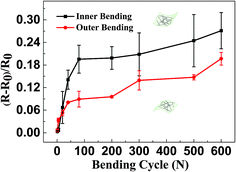 | ||
| Fig. 5 Sheet resistance change of the AgNW/PI TCF (Rs = 7.5 ohm sq−1) after outer and inner bending tests, respectively. | ||
3.4. Thermal properties of AgNW/PI TCFs
As Fig. 6 shows, both pure AgNW film and AgNW/PI film show excellent thermal stability below 200 °C. Heated for 1 hour, the values of ΔR are 0.27 (pure AgNWs film) and 0.08 (AgNW/PI film), respectively. Increasing the heating temperature to 250 °C for 1 hour, the change in sheet resistance of pure AgNWs film was increased obviously. The ΔR of pure AgNW film reached 7.89. This result is because of the pure AgNW network appeared heat-induced welding partial coalescence without the PI protection (Fig. S3†). Instead, Fig. 6 indicated that the AgNW/PI TCF had greater thermostability than the pure AgNW film. Even after annealed at 300 °C for 1 hour, the ΔR of AgNW/PI film was only 0.86. However, the pure AgNW network was destroyed and could not be obtained the resistance value after heating to 300 °C. The AgNWs network was effectively embedded into the PI films, which results the AgNW/PI TCF showed high-temperature stability.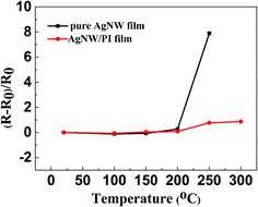 | ||
| Fig. 6 Thermal stability of the AgNW/PI hybrid and pure AgNW film with different annealing temperatures. | ||
To estimate the AgNW/PI TCF long-term reliability, the thermal moisture test was performed by putting the AgNW/PI TCFs into a humidity chamber (121 °C, 97% relative humidity) for 3 hours and 24 hours. 121 °C, 97% relative humidity for 24 hours equivalent to 85 °C, 85% relative humidity for 1000 hours. Fig. S4† shows the electrical properties of AgNW/PI TCF (raw: 5.6 ohm sq−1) and pure AgNW (raw: 6.9 ohm sq−1) after the thermal moisture testing. A slight change in sheet resistance after 3 h for both pure AgNW and AgNW/PI TCF. After 24 h, the pure AgNW resistance rate of change was 142.03%. The increase in resistance of pure AgNW was attributed to oxidation of amounts of AgNW exposed directly in the air. On the contrary, the AgNW/PI TCF changed a little because the PI film protected AgNW from the harsh environment. This result indicates that the hybrid film has better aging resistance than the pure AgNW film.
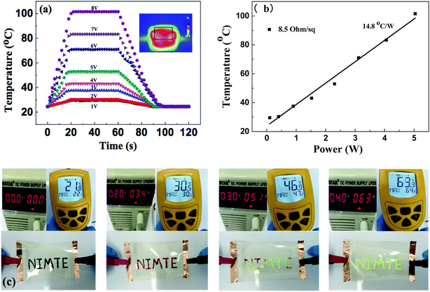
AgNW/PI TCFs could be used as transparent film heaters due to their excellent thermal stability and low sheet resistance. Fig. 7(a) shows the temperature profiles of the AgNW/PI TCF (Rs = 8.5 ohm sq−1), plotted again the input voltage (modulated from 1 V to 8 V). When the input voltage was 1 V, the temperature of the TCF surface reached 29.5 °C. The temperature of TCF surface was increased by increasing the value of the input voltage. When the input voltage was 8 V, the temperature of the TCF surface reached approximately 101.6 °C (Fig. S5†). The inset of Fig. 7(a) is an infrared photograph of the TCF with 6 V input voltage, showing that the temperature distribution on the film surface was uniform. Power consumption is an important parameter for evaluating the film heater performance, which is defined as temperature increase per input electrical power. Based on the data shown in Fig. 7(b) and considering the size of the TCF sample (2.5 cm × 3.5 cm), the electrical power consumption of the TCF was calculated and its value was approximately 203.5 °C cm2 W−1.
The application of AgNW/PI TCF used as transparent film heater with thermochromic material ink was demonstrated as shown in Fig. 7(c). The color of characters, which were written on the TCFs using thermochromic material ink, was changed from dark red to fluorescent green within 10 seconds of the input voltage being increased from 0 V to 4 V.
3.5. Antibacterial properties of AgNW/PI TCFs
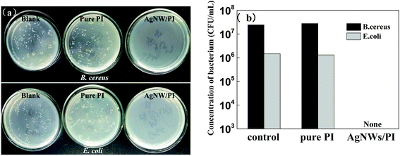
Antibacterial properties also are very important to AgNW/PI TCFs when they were used in special applications, such as wearable devices and electronic skin. Taking this fact into account, we investigated the antibacterial properties of AgNW/PI TCFs (24.5 ohm sq−1) and pure PI films against B. cereus and E. coli which belong to Gram-positive bacterium and Gram-negative bacterium, respectively. The digital photographs of surface plating and the histogram of bacterium concentration are shown in Fig. 8(a) and (b). The results show that the B. cereus concentrations of the blank and pure PI film were 2.45 × 10⁷ CFU mL−1 and 2.78 × 10⁷ CFU mL−1, respectively. The E. coli concentrations of the blank and pure PI film were 1.46 × 10⁶ CFU mL−1 and 1.31 × 10⁶ CFU mL−1, respectively. In contrast to the blank and pure PI film, the AgNW/PI film demonstrates excellent antibacterial effect, as all of the bacteria can be killed. The antibacterial effect of the AgNW/PI composite film may be attributed mainly to the AgNW, which releases silver ions to inhibit bacterial growth by damaging the DNA and protein of the bacteria cells.374. Conclusions
In this study, we have synthesized long AgNWs with a high aspect ratio (>900) in large quantities with a facile modified polyol method. Multifunctional flexible TCFs based on long AgNW/PI structure were fabricated using a scalable, environmentally friendly, and full-solution process. The AgNW/PI composite films show excellent opto-electrical properties (e.g., 7.5 ohm sq−1, at 81.1% transmittance) and mechanical flexibility across a wide temperature range, from room temperature to 300 °C. The thermal response tests of AgNW/PI TCFs were performed to show the higher heating temperature of 101.6 °C at 8 V, and lower electrical power consumption of 203.5 °C cm2 W−1. In addition, the antibacterial properties of the composite films were also studied. The AgNW/PI TCFs shows high resistance to B. cereus and E. coli. These characteristics make the composite films an excellent candidate for substrates for flexible and wearable electronic devices with antibacterial needs.Author contributions
The manuscript was written through contributions of all authors. All authors have given approval to the final version of the manuscript.Conflict of interest
The authors declare no competing financial interest.Acknowledgements
This work has been supported by the Zhejiang Provincial Natural Science Foundation of China (Grant No. LY15B050003), the National Natural Science Foundation of China (Grant No. 51403225, 21377063), Ningbo Municipal Science and Technology Innovative Research Team (2016B10005). Thanks much to Gayle Barton and Yixin Xiao for help with the manuscript writing.Notes and references
- R. E. Triambulo and J. W. Park, Curr. Appl. Phys., 2015, 15, S12–S16 CrossRef.
- D. S. Hecht, L. B. Hu and G. Irvin, Adv. Mater., 2011, 23(13), 1482–1513 CrossRef CAS PubMed.
- M. Golobostanfard, H. Abdizadeh, S. Mohammadi and M. Baghchesara, Sol. Energy Mater. Sol. Cells, 2015, 132, 418–424 CrossRef CAS.
- A. Kim, Y. Won, K. Woo, S. Jeong and J. Moon, Adv. Funct. Mater., 2014, 24, 2462–2471 CrossRef CAS.
- K. Zilberberg, F. Gasse, R. Pagui, A. Polywka, A. Behrendt, S. Trost, R. Heiderhoff, P. Gorrn and T. Riedl, Adv. Funct. Mater., 2014, 24(12), 1671–1678 CrossRef CAS.
- J. Song and H. Zeng, Angew. Chem., Int. Ed. Engl., 2015, 54(34), 9760–9774 CrossRef CAS PubMed.
- J.-Y. Kim, J.-H. Jeon and M.-K. Kwon, ACS Appl. Mater. Interfaces, 2015, 7, 7945–7950 CAS.
- I. Ryu, G. Kim, D. Park and S. Yim, J. Power Sources, 2015, 297, 98–104 CrossRef CAS.
- D. Nguyen and H. Yoon, Polymers, 2016, 8(118), 1–38 Search PubMed.
- S. Jiang, H. Zhang, S. Song, Y. Ma, J. Li, G. Lee, Q. Han and J. Liu, ACS Nano, 2015, 9, 10252–10257 CrossRef CAS PubMed.
- A. Sundramoorthy, Y.-C. Wang and S. Gunasekaran, Nano Res., 2015, 8, 3430–3445 CrossRef CAS.
- J. Jo, J. Lee and W. Jo, Polym. Int., 2015, 64, 1676–1684 CrossRef CAS.
- M. Singh, T. Rana, S. Kim, K. Kim, J. Yun and J. Kim, ACS Appl. Mater. Interfaces, 2016, 8, 12764–12771 CAS.
- Y. Jia, C. Chen, D. Jia, S. Li, S. Ji and C. Ye, ACS Appl. Mater. Interfaces, 2016, 8, 9865–9871 CAS.
- W. Xiong, H. Liu, Y. Chen, M. Zheng, Y. Zhao, X. Kong, Y. Wang, X. Zhang, X. Kong, P. Wang and L. Jiang, Adv. Mater., 2016, 28(33), 7167–7172 CrossRef CAS PubMed.
- Y.-L. Tai and Z.-G. Yang, Langmuir, 2015, 31, 13257–13264 CrossRef CAS PubMed.
- J. Shaw, A. Perumal, D. Bradley, P. Stavrinou and T. Anthopoulos, J. Appl. Phys., 2016, 119, 195501 CrossRef.
- B. Deng, P.-C. Hsu, G. Chen, B. Chandrashekar, L. Liao, Z. Ayitimuda, J. Wu, Y. Guo, L. Lin, Y. Zhou, M. Aisijiang, Q. Xie, Y. Cui, Z. Liu and H. Peng, Nano Lett., 2015, 15(6), 4206–4213 CrossRef CAS PubMed.
- T.-B. Song, Y. Rim, F. Liu, B. Bob, S. Ye, Y.-T. Hsieh and Y. Yang, ACS Appl. Mater. Interfaces, 2015, 7, 24601–24607 CAS.
- Y. Jin, D. Deng, Y. Cheng, L. Kong and F. Xiao, Nanoscale, 2014, 6, 4812–4818 RSC.
- B. Li, S. Ye, I. Stewart, S. Alvarez and B. Wiley, Nano Lett., 2015, 15(10), 6722–6726 CrossRef CAS PubMed.
- Q. Xu, W. Shen, Q. Huang, Y. Yang, R. Tan, K. Zhu, N. Dai and W. Song, J. Mater. Chem. C, 2014, 2, 3750–3755 RSC.
- M. Song, D. You, K. Lim, S. Park, S. Jung, C. Kim, D. Kim, D. Kim, J. Kim, J. Park, Y. Kang, J. Heo, S. Jin, J. Park and J. Kang, Adv. Funct. Mater., 2013, 23, 4177–4184 CrossRef CAS.
- J. Spechler, T. Koh, J. Herb, B. Rand and C. Arnold, Adv. Funct. Mater., 2015, 25, 7428–7434 CrossRef.
- D. Ghosh, T. Chen, V. Mkhitaryan and V. Pruneri, ACS Appl. Mater. Interfaces, 2014, 6, 20943–20948 CAS.
- Q. Huang, W. Shen, X. Fang, G. Chen, Y. Yang, J. Huang, R. Tan and W. Song, ACS Appl. Mater. Interfaces, 2015, 7, 42994305 Search PubMed.
- Q. Huang, W. Shen, X. Fang, G. Chen, J. Guo, W. Xu, R. Tan and W. Song, RSC Adv., 2015, 5, 45836–45842 RSC.
- Y. Jiang, J. Xi, Z. Wu, H. Dong, Z. Zhao, B. Jiao and X. Hou, Langmuir, 2015, 31(17), 4950–4957 CrossRef CAS PubMed.
- R. Mutiso, M. Sherrott, A. Rathmell, B. Wiley and K. Winey, ACS Nano, 2013, 7, 7654–7663 CrossRef CAS PubMed.
- S. Ye, A. R. Rathmell, Z. Chen, L. E. Stewart and B. Wiley, J. Adv. Mater., 2014, 26, 6670–6687 CrossRef CAS PubMed.
- S. De and J. N. Coleman, MRS Bull., 2011, 36, 774–781 CrossRef CAS.
- J. T. Li and S. L. Zhang, Phys. Rev. E: Stat., Nonlinear, Soft Matter Phys., 2009, 80, 040104 CrossRef PubMed.
- M. Lagrange, D. P. Langley, G. Giusti, C. Jiménez, Y. Bréchet and D. Bellet, Nanoscale, 2015, 7, 17410–17423 RSC.
- A. Bid, A. Bora and A. K. Raychaudhuri, Phys. Rev. B: Condens. Matter Mater. Phys., 2006, 74, 035426 CrossRef.
- G. Haacke, J. Appl. Phys., 1976, 47, 4086–4089 CrossRef CAS.
- B. J. Kim, Jpn. J. Appl. Phys., 2016, 55(6S3), 06JF01 CrossRef.
- D. Wei, W. Sun, W. Qian, Y. Ye and X. Ma, Carbohydr. Res., 2009, 344, 2375–2382 CrossRef CAS PubMed.
Footnote |
| † Electronic supplementary information (ESI) available: Preparation process of AgNWs; sheet resistance change of the AgNW/PI TCF with 3M taping test; surface morphologies of pure AgNW film before (a) and after (b) annealed at 250 °C for 1 h; the change of the sheet resistance after the thermal moisture test in a humidity chamber (121 °C, 97% relative humidity); temperature change of the AgNW/PI TCF (Rs = 8.5 ohm sq−1) with different input voltages; cycling performance of AgNW/PI TCF with sheet resistance of 8.5 ohm sq−1. See DOI: 10.1039/c7ra04569g |
| This journal is © The Royal Society of Chemistry 2017 |


