 Open Access Article
Creative Commons Attribution 3.0 Unported Licence
DBP and C70 based inverted tandem solar cells using a simple interconnecting layer†
Zhongqiang Wang *a,
Takeshi Sanob,
Taojun Zhuangb,
Hisahiro Sasabeb and
Junji Kido*b
aKey Laboratory of Interface Science and Engineering in Advanced Materials (Ministry of Education), Research Center of Advanced Materials Science and Technology, Taiyuan University of Technology, Taiyuan, 030024, China. E-mail: wangzhongqiang@tyut.edu.cn
bDepartment of Organic Device Engineering, Graduate School of Science and Engineering, Research Center for Organic Electronics (ROEL), Yamagata University, 4-3-16 Jonan, Yonezawa, Yamagata 992-8510, Japan. E-mail: kid@yz.yamagata-u.ac.jp
First published on 11th July 2017
Abstract
Inverted tandem structure cells with a simple interconnecting layer based on tetraphenyldibenzoperiflanthene (DBP) and fullerene-70 (C70) were studied in this work. Two subcells using identical donor and acceptor materials were connected by a molybdenum trioxide and calcium (MoO3/Ca) interlayer in series. An outstanding fill factor (over 80%) under concentrated power intensity has been observed. Meanwhile, the open circuit voltage is approximately equal to the sum of the two subcells, revealing the excellent properties of MoO3/Ca as a recombination layer for tandem structured cells. On the other hand, the main loss mechanisms of charge carriers are analyzed; Schokley–Read–Hall and bimolecular recombination dominate the charge recombination in the tandem structured cells under low and high power intensities, respectively.
Introduction
As a potential technology for clear and renewable energy, the performance of organic photovoltaic cells (OPVs) has been dramatically enhanced, which makes this technology a competitive alternative to inorganic photovoltaic cells.1–4 OPVs using conjugated polymer and small-molecule electron donor materials blended with fullerene and non-fullerene materials as electron acceptor materials have achieved over 12% power conversion efficiency (PCE) in single bulk heterojunction (BHJ) structured devices.2–5 In recent years, much attention has been paid to the field of small-molecule based OPVs, and to date the PCE have reached 10% and 12% in single- and multi-junction cells, respectively.4,6 However, the intrinsic properties (low charge mobility, short exciton diffusion length, narrow absorption bandwidth) of organic semiconductors limit further improvement in OPVs. For more effectively improving the performance, a simple and useful method is to design tandem structure cells via stacking multiple photoactive layers with complementary absorption spectra.5,7,8 Meanwhile, subcells using identical materials have also been tried in polymer based tandem structure cells. Comparison with single junction cells, the tandem structure cells with identical materials show enhanced light harvesting and decreased charge carriers recombination. Usually, the tandem structure has positive contribution to the photovoltaic performance.9–11The typical tandem structure cells are connected with subcells in series through interconnecting layers. An effective and simple interconnecting layer not only affects the performance of cells but also influences the device procedure. Due to the multiple effects, the interconnecting layer plays a key role in tandem structure cells. For a good interconnecting layer, it should satisfy some requirements, including high conductivity, excellent transparency and easy processing.12 Hence, n-type metal oxides with high conductivity are widely selected as connecting layers in tandem structure cells.13,14 In this paper, molybdenum trioxide (MoO3) and calcium (Ca) were applied as hole and electron collecting layers in each subcells. Meanwhile, MoO3/Ca was used as the recombination layer in tandem structure cells. More importantly, our results proved that MoO3/Ca is an efficient charge carrier recombination center for tandem structure cells. On the other hand, photovoltaic performance and inside recombination mechanism were studied in this tandem structure cells.
Experimental
Tetraphenyldibenzoperiflanthene (DBP) and fullerene-70 (C70) were purified three times by thermal sublimation. Pre-patterned indium–tin-oxide (ITO) coated substrates were cleaned by detergent, deionized water, acetone and isopropanol in sonication, and treated in UV-ozone for 30 min before loading into vacuum chamber. The organic layers and metal electrodes were thermally deposited in sequence on pre-cleaned substrates in a vacuum chamber with base pressure of 1 × 10⁻⁶ Pa. The thicknesses and deposition rates were monitored by quartz crystal sensors. The deposited rates of organic materials were controlled at 0.2–0.3 Å s−1. Aluminum (Al) deposited rate was ∼5 Å s−1. The active area of individual OPVs is ∼3 × 3 mm2, defined by the overlap of the ITO and Al electrodes. The made-up cells were transferred back to a nitrogen protected glovebox for encapsulation, and then brought to ambient condition for measurement of both efficiency (PCE and EQE) and current density–voltage (J–V) characteristics using a CEP-2000 integrated system by Bunkoukeiki Co. Light state J–V characteristics were measured under simulated 100 mW cm−2 AM1.5G irradiation. Integrating current density from EQE curve under AM1.5G solar spectrum showed <5% discrepancy with Jsc extracted from J–V curves.Results and discussion
Fig. 1(a) shows the tandem device configuration and Fig. 1(b) shows the chemical structure of DBP and C70. As discussed in ref. 15, much interaction between DBP and C70 on a molecular level were allowed due to the planar backbone of DBP molecule, which contributes to the strong charge transfer states in DBP and C70 heterojunction system.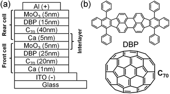 | ||
| Fig. 1 (a) Configuration of inverted tandem solar cells. The shown thicknesses were the optimal values for DBP and C70 based tandem structure cell. (b) Chemical structures of DBP and C70. | ||
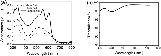
We adopted the inverted tandem structure to achieve stable and reproducible cells. Moreover, we employed DBP and C70 system in tandem structure cells for efficient light harvesting. As shown in Fig. 2(a), the absorption of the two C70/DBP subcells has been significantly enhanced compared with the single junctions (front cell and rear cell).
In designing high performance interconnecting layer in tandem structure cells, good transmittance is the first priority. Therefore, the transmittance of MoO3/Ca interlayer was studied. As shown in Fig. 2(b), the interconnecting layer of MoO3/Ca displays high transmittance in the range from 300 nm to 800 nm. The value of transmittance is over 99% when the wavelength is beyond 500 nm. The high transmittance benefits the light absorption in tandem structure cells.
Excellent photovoltaic property of DBP has been confirmed in our past work. Relevant papers were published in ref. 15 and 16. The complementary absorption spectra of DBP and C70 show strong absorption from near UV range to about 650 nm. High extinction coefficient and anisotropy property have been observed in vacuum deposited DBP films. The highest occupied molecular orbital (HOMO) and lowest unoccupied molecular orbital (LUMO) energy levels of DBP are −5.5 eV and −3.5 eV, respectively. As a result, high open circuit voltage (Voc) of 0.9 V was obtained in DBP/C70 planar junction cells, consistenting with the difference between HOMO energy level of DBP and LUMO energy level of C70.17 The energy level diagram was shown in ESI Fig. SI 1.†
As a recombination layer, the contact between MoO3 and Ca dominates the performance in tandem structure cells. Therefore, experiment was designed to study the interfacial contact between MoO3 and Ca. As shown in ESI Fig. SI 2 and Table SI 1,† the optimal Ca thickness was set to 1 nm. Two device structures were designed: device (I) ITO/Ca (1 nm)/C70 (40 nm)/DBP (20 nm)/MoO3 (5 nm)/Al, device (II) ITO/MoO3 (5 nm)/Ca (1 nm)/C70 (40 nm)/DBP (20 nm)/MoO3 (5 nm)/Al. The photovoltaic performances of device (I) and device (II) were summarized in Table 1. As listed in the table, similar Jsc, Voc, FF and PCE were achieved from device (I) and (II). Meanwhile, the series resistance (Rs) and shunt resistance (Rsh) of device (I) and (II) were extracted from J–V curves, which were also similar. Comparable photovoltaic performance and resistances mean good electrical contact between MoO3 and Ca. On the other hand, the optical transparency of MoO3 film has been confirmed in OPVs.18,19 Therefore, MoO3/Ca could be qualified for interconnecting layer in tandem structure cells.
| Device | Jsc (mA cm−2) | Voc (V) | FF (%) | PCE% | Rs (Ω cm−2) | Rsh (Ω cm−2) |
|---|---|---|---|---|---|---|
| I | 5.56 | 0.89 | 73 | 3.59 | 11.74 | 3779.20 |
| II | 5.69 | 0.9 | 69 | 3.5 | 12.27 | 3022.92 |
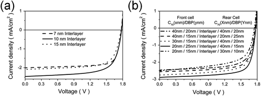
In tandem structure cells, the interconnecting layer not only affects the charge carrier collection, but also influences the optical transmission.20 Thus, another important concern that needs to be addressed is the thickness of interlayer. Actually, the interconnecting layer in tandem cells was the hole-collecting layer of front cell and electron-collecting layer of rear cell, which was tuned from 7 nm to 15 nm. Based on our previous study, the active layers thickness of C70 and DBP were set to 40 nm and 20 nm in both subcells.15 The J–V curves with different interconnecting layer thicknesses were shown in Fig. 3(a), the parameters extracted from J–V curves were summarized in Table 2. The highest PCE obtained from such a tandem structure cell was 3.07% when the interlayer thickness was 10 nm (MoO3 (5 nm)/Ca (5 nm)), with a Voc of 1.76 V, a Jsc of 2.46 mA cm−2 and a FF of 71%. It can be found that the tandem structure cells showed a Voc of 1.76 V, which is approximately equal to the sum of the two subcells. Due to the discontinuous film of Ca (2 nm), the Jsc in tandem structure cell with 7 nm interlayer is only 2 mA cm−2. Meanwhile, the Jsc of tandem structure cell is 2.08 mA cm−2 when the interlayer thickness is 15 nm, which should be attributed to the energy barrier caused by thick interconnecting layer.21,22
| MoO3 (P nm) | Ca (Q nm) | Jsc (mA cm−2) | Voc (V) | FF% | PCE% |
|---|---|---|---|---|---|
| 5 | 5 | 2.46 | 1.76 | 71 | 3.07 |
| 5 | 2 | 2 | 1.77 | 77 | 2.70 |
| 10 | 5 | 2.08 | 1.77 | 71 | 2.61 |
In ideal series tandem structure cells, Voc is sum of the Voc of each subcells, Jsc is dominated by the smaller one of subcells if the fill factor (FF) is the same in both subcells.23 Due to spectral overlap and variation of optical field distribution, Jsc and FF in tandem structure cells differ from the values in subcells. Hence, the Jsc in tandem structure cell is controlled by the subcell with high FF.24 Therefore, the thickness of active layers in each subcells were tuned in order to optimize the photovoltaic performance of tandem structure cell. Optimizing the thickness of active layers, the front and rear cells were designed to absorb the long-wave light photons and short-wave light photons, respectively.
For comparison, the J–V curves using different thickness active layers were plotted in Fig. 3(b), the corresponding parameters were summarized in Table 3. The optimal device performance was obtained when the active layers thicknesses of front and rear cells were set to C70 (20 nm)/DBP (25 nm) and C70 (40 nm)/DBP (15 nm), with a PCE of 3.81%, a Voc of 1.77 V, a Jsc of 2.89 mA cm−2 and a FF of 74%. In order to diminish the absorption overlap of acceptor, C70 was changed to C60 in front subcell. However, the performance of tandem structure cell decreased due to the low Jsc, which was ascribed to the weaker absorption of C60 in visible region. The J–V curve was shown in ESI (Fig. SI 3†).
| Front cell C70 (x nm) | Front cell DBP (y nm) | Rear cell C70 (X nm) | Rear cell DBP (Y nm) | Jsc (mA cm−2) | Voc (V) | FF% | PCE% |
|---|---|---|---|---|---|---|---|
| 40 | 20 | 40 | 20 | 2.46 | 1.76 | 71 | 3.07 |
| 40 | 15 | 20 | 25 | 2.56 | 1.77 | 72 | 3.24 |
| 30 | 15 | 40 | 20 | 2.75 | 1.76 | 70 | 3.38 |
| 20 | 25 | 40 | 15 | 2.89 | 1.77 | 74 | 3.81 |
| 20 | 15 | 30 | 10 | 2.51 | 1.76 | 65 | 2.87 |
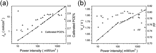
It has been proved that the dependence of Jsc on incident light intensity reflects the charge carrier recombination behavior in solar cells.25,26 To understand the recombination behaviors in tandem structure cells, Jsc as a function of light intensity has been studied in this work, which is determined from the expression:27
| Jsc ∝ Iα | (1) |
Under open circuit operating condition, no charge carriers are extracted and the generated charge carriers recombine again in solar cells, which effectively reflects the inside recombination behaviors. Hence, the recombination behaviors can be revealed by the dependence of Voc upon light intensity. Fig. 4(b) showed Voc as a function of the logarithmic scale of light intensity. The experimental data were fitted with a linear function with slope S,  (from 10 to 100 mW cm−2),
  (from 150 to 2400 mW cm−2). It has been proved that S gives
  for bimolecular recombination.29 However, the experimental data showed a steeper dependence of Voc on the light intensity. This deviation has been explained by adding trap-assisted Schokley–Read–Hall (SRH) recombination at the donor and acceptor interface in organic solar cells.30,31 Due to the competition of SRH and bimolecular recombination, the slope of Voc with logarithmic scale on light intensity increased with the strength of trap-assisted recombination. The slope under low light intensity is higher than it under high light intensity, which means SRH recombination is more dominant than bimolecular recombination at low light intensity. On the other hand, a low charge carrier mobility in organic semiconductor can boost the formation of space charge giving rise to bimolecular recombination of electrons and holes. Hence, the bimolecular recombination becomes stronger and eventually dominant the inside recombination mechanism of device.32 Hence, SRH recombination mechanism is the main loss mechanism in this inverted tandem structure cells. Fig. 4(b) also showed the dependence of FF under light intensity, high FF (79% under 100 mW cm−2) was observed. Outstanding FF (over 80%) was obtained when the light intensity was about 200 mW cm−2, which was the highest value reported in organic solar cells.
Photovoltaic cells are working under sunlight in the air. Hence, stability is another key issue for OPVs. In this work, we study the stability of inverted tandem structure cell. As shown in Fig. 5, the encapsulated cells showed good stability in air. The tandem structure cell showed steep decreasing in five days, the Jsc decreased from 2.89 mA cm−2 to 2.16 mA cm−2. After that the performance of tandem structure cell became stable. On the other hand, the Voc showed weak decay in 30 days. This result displays that stability of inverted tandem structure cell is good in DBP and C70 based planar heterojunction cells.
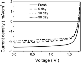 | ||
| Fig. 5 Stability comparison in air of tandem structure cell. Device structure: ITO/Ca (1 nm)/C60 (20 nm)/DBP (25 nm)/MoO3 (5 nm)/Ca (5 nm)/C70 (40 nm)/DBP (15 nm)/MoO3 (5 nm)/Al. | ||
Conclusions
Inverted tandem structure cells with identical subcells has been studied. This study proved that MoO3 and Ca is an effective interconnecting layer for vacuum deposited tandem structure cells. On the other hand, charge carrier recombination behaviors are revealed that Schokley–Read–Hall recombination and bimolecular recombination dominates the loss mechanism of cells under low light intensity and high light intensity, respectively. Compared with single junction solar cell, improved PCE, impressive FF and good stability are observed in tandem structure cell. With certain modification, inverted tandem structure could be a potential candidate for improving photovoltaic performance and stability.Acknowledgements
This project is sponsored under the Japan Science and Technology Agency (JST) via the Japan Regional Innovation Strategy Program by the Excellence (J-RISE).This research was also supported by Shanxi Provincial Natural Science Foundation of China (Grant No. 201601D021050). This study was also supported by the Qualified Personal Foundation of Taiyuan University of Technology (800101-02030017).References
- J. Jo, J.-R. Pouliot, D. Wynands, S. D. Collins, J. Y. Kim, T. L. Nguyen, H. Y. Woo, Y. Sun, M. Leclerc and A. J. Heeger, Adv. Mater., 2013, 25, 4783 CrossRef CAS PubMed.
- W. Zhao, S. Li, S. Zhang, X. Liu and J. Hou, Adv. Mater., 2017, 29, 1604059 CrossRef PubMed.
- D. Baran, R. S. Ashraf, D. A. Hanifi, M. Abdelsamie, N. Gasparini, J. A. Röhr, S. Holliday, A. Wadsworth, S. Lockett, M. Neophytou, C. J. M. Emmott, J. Nelson, C. J. Brabec, A. Amassion, A. Salleo, T. Kirchartz, J. R. Durrant and I. McCulloch, Nat. Mater., 2017, 16, 363–369 CrossRef CAS PubMed.
- M. Li, K. Gao, X. Wan, Q. Zhang, B. Kan, R. Xia, F. Liu, X. Yang, H. Feng, W. Ni, Y. Wang, J. Peng, H. Zhang, Z. Liang, H.-L. Yip, X. Peng, Y. Cao and Y. Chen, Nat. Photonics, 2017, 11, 85–90 CrossRef CAS.
- F. Zhao, S. Dai, Y. Wu, Q. Zhang, J. Wang, L. Jiang, Q. Ling, Z. Wei, W. Ma, W. You, C. Wang and X. Zhan, Adv. Mater., 2017, 1700144 CrossRef PubMed.
- Q. Zhang, B. Kan, F. Liu, G. Long, X. Wan, X. Chen, Y. Zuo, W. Ni, H. Zhang, M. Li, Z. Hu, F. Huang, Y. Cao, Z. Liang, M. Zhang, T. P. Russell and Y. Chen, Nat. Photonics, 2015, 9, 35–41 CrossRef CAS.
- Y. Ma, S.-C. Chen, Z. Wang, W. Ma, J. Wang, Z. Yin, C. Tang, D. Cai and Q. Zheng, Nano Energy, 2017, 33, 313–324 CrossRef CAS.
- M. Riede, C. Uhrich, J. Widmer, R. Timmreck, D. Wynands, G. Schwartz, W.-M. Gnehr, D. Hildebrandt, A. Weiss, J. Hwang, S. Sundarraj, P. Erk, M. Pfeiffer and K. Leo, Adv. Funct. Mater., 2011, 21, 3019 CrossRef CAS.
- S.-C. Chen, Q. Zheng, Z. Yin, D. Cai and Y. Ma, Org. Electron., 2017, 47, 79–84 CrossRef CAS.
- X. W. Sun, D. W. Zhao, L. Ke, A. K. K. Kyaw, G. Q. Lo and D. L. Kwong, Appl. Phys. Lett., 2010, 97, 053303 CrossRef.
- J. You, C.-C. Chen, Z. Hong, K. Yoshimura, K. Ohya, R. Xu, S. Ye, J. Gao, G. Li and Y. Yang, Adv. Mater., 2013, 25, 3973 CrossRef CAS PubMed.
- W. Liu, S. Li, J. Huang, S. Yang, J. Chen, L. Zuo, M. Shi, X. Zhan, C.-Z. Li and H. Chen, Adv. Mater., 2016, 28, 9729–9734 CrossRef CAS PubMed.
- D. W. Zhao, X. W. Sun, C. Y. Jiang, A. K. K. Kyaw, G. Q. Lo and D. L. Kwong, Appl. Phys. Lett., 2008, 93, 083305 CrossRef.
- J. Y. Kim, K. Lee, N. E. Coates, D. Moses, T.-Q. Nguyen, M. Dante and A. J. Heeger, Science, 2007, 317, 222 CrossRef CAS PubMed.
- D. Yokoyama, Z. Wang, Y.-J. Pu, K. Kobayashi, J. Kido and Z. Hong, Sol. Energy Mater. Sol. Cells, 2012, 98, 472–475 CrossRef CAS.
- Z. Wang, D. Yokoyama, X.-F. Wang, Z. Hong, Y. Yang and J. Kido, Energy Environ. Sci., 2013, 6, 249–255 CAS.
- M. C. Scharber, D. Mühlbacher, M. Koppe, P. Denk, C. Waldauf, A. J. Heeger and C. J. Brabec, Adv. Mater., 2006, 18, 789 CrossRef CAS.
- Y. Sun, C. J. Takacs, S. R. Cowan, J. H. Seo, X. Gong, A. Roy and A. J. Heeger, Adv. Mater., 2011, 23, 2226 CrossRef CAS PubMed.
- Y.-C. Tseng, A. U. Mane, J. W. Elam and S. B. Darling, Sol. Energy Mater. Sol. Cells, 2012, 99, 235 CrossRef CAS.
- Y. Yuan, J. Huang and G. Li, Green, 2011, 1, 65–80 CrossRef CAS.
- X. W. Sun, D. W. Zhao, L. Ke, A. K. K. Kyaw, G. Q. Lo and D. L. Kwong, Appl. Phys. Lett., 2010, 97, 053303 CrossRef.
- S. Sista, M.-H. Park, Z. Hong, Y. Wu, J. Hou, W. L. Kwan, G. Li and Y. Yang, Adv. Mater., 2010, 22, 380–383 CrossRef CAS PubMed.
- A. Hadipour, B. D. Boer and P. W. M. Blom, Org. Electron., 2008, 9, 617–624 CrossRef.
- S. Sista, Z. Hong, L.-M. Chen and Y. Yang, Energy Environ. Sci., 2011, 4, 1606–1620 CAS.
- R. A. Street and M. Schoendorf, Phys. Rev. B: Condens. Matter Mater. Phys., 2010, 81, 205307 CrossRef.
- A. K. K. Kyaw, D. H. Wang, V. Gupta, W. L. Leong, L. Ke, G. C. Bazan and A. J. Heeger, ACS Nano, 2013, 7, 4569–4577 CrossRef CAS PubMed.
- J. K. J. V. Duren, X. Yang, J. Loos, C. W. T. Bulle-Lieuwma, A. B. Sieval, J. C. Hummelen and R. A. J. Janssen, Adv. Funct. Mater., 2004, 14, 425–434 CrossRef.
- I. Riedel, J. Parisi, V. Dyakonov, L. Lutsen, D. Vanderzande and J. C. Hummelen, Adv. Funct. Mater., 2004, 14, 38–44 CrossRef CAS.
- S. R. Cowan, A. Roy and A. J. Heeger, Phys. Rev. B: Condens. Matter Mater. Phys., 2010, 82, 245207 CrossRef.
- M. M. Mandoc, W. Veurman, L. J. A. Koster, B. D. Boer and P. W. M. Blom, Adv. Funct. Mater., 2007, 17, 2167–2173 CrossRef CAS.
- K. S. Nalwa, R. C. Mahadevapuram and S. Chaudhary, Appl. Phys. Lett., 2011, 98, 093306 CrossRef.
- Z. Wang, Z. Hong, T. Zhuang, G. Chen, H. Sadabe, D. Yokoyama and J. Kido, Appl. Phys. Lett., 2015, 106, 053305 CrossRef.
Footnote |
| † Electronic supplementary information (ESI) available. See DOI: 10.1039/c7ra04501h |
| This journal is © The Royal Society of Chemistry 2017 |

