DOI:
10.1039/C7RA04248E
(Paper)
RSC Adv., 2017,
7, 30564-30572
Preparation of organic–inorganic hybrid membranes with superior antifouling property by incorporating polymer-modified multiwall carbon nanotubes
Received
14th April 2017
, Accepted 8th June 2017
First published on 14th June 2017
Abstract
Functionalized multiwall carbon nanotubes (MWCNTs) were prepared by coating polyvinylpyrrolidone (PVP) on the MWCNTs surface via multiple hydrogen-bonding interactions between polyvinylpyrrolidone and a mussel-inspired polydopamine (PDA) intermediate. The modified MWCNTs exhibited outstanding dispersity and stability in water and were used as a hydrophilic additive to increase the permeability and antifouling properties of polyethersulfone (PES) ultrafiltration membranes. The results of Fourier transform infrared spectroscopy (FTIR) and X-ray photoelectron spectroscopy (XPS) confirmed the introduction of PDA and PVP into the MWCNTs. The measured water contact angle of the hybrid membranes revealed dramatically enhanced hydrophilicity. The morphology of the hybrid membranes was investigated by field emission scanning electron microscopy (FESEM). Furthermore, the permeability and antifouling properties of the hybrid membranes when mixed with different types and quantities of MWCNTs were compared. The hybrid membrane containing 0.1% PVP-modified MWCNTs exhibited the best overall performance, including a flux recovery ratio as high as 95%. The facile and universal treatment method developed in the present study can be used to improve the comprehensive performance of membranes, with great potential application in wastewater treatment.
1 Introduction
Shortage of clean water has been one of the critical environmental problems faced by humans in recent years, with industrial waste water discharge and ship oil leaks aggravating the water pollution problem.1 Membrane separation technology has increasingly attracted attention for use in addressing this problem because of its low cost and facile operation. Separation membranes are divided into a number of categories, namely, microfiltration (MF), ultrafiltration (UF), nanofiltration (NF), and reverse osmosis (RO) membranes, depending on the size of the pore or the separated materials. Typically, UF membranes are used for the separation of colloid particles, macromolecular proteins, dye molecules, and bacteria based on the size-sieving effect.2–4
Polyethersulfone (PES) is an advanced engineering material and widely used in the wastewater treatment.5 However, one of the main limitations of membrane separation technology is membrane fouling, which is considered to be primarily caused by the hydrophobic effect between pollutants and the membrane surface.6–8 Unfortunately, PES is characterized by hydrophobicity, which induces membrane deterioration.5 To address this issue, many modification methods including surface coating, bulk modification, and introduction of inorganic nanomaterials have been investigated for making the membrane more hydrophilic. Fabrication of organic–inorganic hybrid membrane is a feasible method to combine the advantages of organic materials, such as flexibility and processability, and the advantages of inorganic materials, such as mechanical and thermal stability. Halloysite nanotubes,9,10 SiO2,11 TiO2,12 graphite oxide,13 and carbon nanotubes (CNTs)14–17 have been integrated into separation membranes in several previous studies. CNTs are considered as potential candidates for such use due to their many unique characteristics, which include large surface area, high length to diameter ratio, and excellent mechanical strength. In particular, CNTs have a hollow tubular structure, which can favorably function as a transport channel for water molecules.18 Thus, the introduction of CNTs into a membrane matrix would significantly enhance the membrane permeability. Nevertheless, CNTs tend to aggregate into bundles due to their strong van der Waals interactions, and this makes their uniform dispersal difficult in various solvents and polymer membranes.19 Various CNTs modification methods have been developed in previous studies, and these have contributed to making the material one of the most attractive for use in enhancing the performance of separation membranes. For example, the surface properties of polyvinylidene fluoride (PVDF) membranes integrated with hyperbranched poly(amine ester) modified with MWCNTs have been investigated, and the modified membranes were found to exhibit improved antifouling properties.20 In situ polymerization is another important means of modifying CNTs. Parisa Daraei et al. conducted a comprehensive study on the effects of four different functionalized multiwall carbon nanotubes (MWCNTs) on composite membranes, with the membrane containing PCA-CNT found to exhibit a flux recovery ratio as high as 95%.17 CNTs have been used to improve membrane performance not only by blending into the membrane, but also by coating on the membrane surface. Langming Bai et al. successfully synthesized PEO-functionalized CNTs and used them to coat a PES UF membrane. The modified membranes exhibited a reasonably low flux decline because the CNTs obstructed their being contacted by pollutants.21 Despite the abundant studies that have been conducted on CNT functionalization and dispersion, the improvement of hydrophilicity of CNTs remains a serious challenge to their application in separation membrane.
Recently, dopamine has received a great deal of attention, owing to its unique properties. Under oxidation and weak alkaline conditions, dopamine undergoes self-polymerization in an aqueous solution to generate polydopamine (PDA).22 Extensive studies have suggested that PDA can adsorbed onto various basement membranes (PVDF, PES, and polypropylene) and nanomaterials such as SiO2, graphene oxide, and halloysite nanotubes10 through π–π stacking, hydrogen bonding, action of vander Waals forces, and chelation. Although PDA has been used to improve the hydrophilicity and dispersion of CNTs,23,24 the results are not particularly satisfactory. How to further improve the hydrophilicity and dispersibility of CNTs is an urgent problem to be solved. PVP, as a water-soluble polymer, is widely used to improve the hydrophilicity of membrane materials and nanomaterials. It is regarded as a promising candidate for use in optimizing the properties of separation membranes, including their permeability and fouling resistance.25,26 Moreover, PVP can adsorb PDA via multiple hydrogen-bonding interactions, which makes PVP modify CNTs feasible.
Overall, the methods that have so far been proposed for modifying CNTs are complex, expensive, or hazardous. The development of a versatile, facile, and effective method for improving the hydrophilicity of CNTs remains a major challenge in separation membrane. In the present study, we used a simple two-steps method to improve the dispersity and hydrophilicity of MWCNTs. PVP strongly adsorbed onto the MWCNTs surface via multiple hydrogen-bonding interactions between PVP and PDA. Two types of polymer-modified MWCNTs were prepared and respectively mixed into casting solutions to fabricate a series of organic–inorganic hybrid membranes. The morphology, surface hydrophilicity, permeability, and antifouling properties of the membranes were fully investigated.
2 Experiment
2.1 Materials
The PES (Ultrason E6020P) used as the UF membrane matrix material in the present study was supplied by BASF. The employed MWCNTs (length 10–30 μm and outer diameter 10–20 nm) were obtained from Chengdu Organic Chemicals Co., Ltd., Chinese Academy of Science. The hydrochloric acid and tri(hydroxymethyl) aminomethane (Tris) used to prepare the Tris–HCl buffer solution (pH = 8.5) were purchased from Aladdin. Na2HPO4·12H2O and NaH2PO4·2H2O were obtained from XiLong and used to prepare the phosphate buffer solution (pH = 7.4). The utilized PVP (Mw = 30![[thin space (1/6-em)]](https://www.rsc.org/images/entities/char_2009.gif) 000 g mol−1) and dopamine hydrochloride were also obtained from Aladdin, while the bovine serum albumin (BSA, pI = 4.8, Mw = 67000 g mol−1) was purchased from Shanghai LanJi. N,N-dimethylformamide (DMF) purchased from Sigma-Aldrich was used as a solvent for the polymer. Deionized water was used as coagulation bath and in the UF process.
000 g mol−1) and dopamine hydrochloride were also obtained from Aladdin, while the bovine serum albumin (BSA, pI = 4.8, Mw = 67000 g mol−1) was purchased from Shanghai LanJi. N,N-dimethylformamide (DMF) purchased from Sigma-Aldrich was used as a solvent for the polymer. Deionized water was used as coagulation bath and in the UF process.
2.2 Preparation of PVP-modified MWCNTs
The detailed steps of the preparation of the PVP-modified MWCNTs are as follows. 100 mg of MWCNTs were added to 100 ml of freshly prepared Tris–HCl buffer solution (pH = 8.5). After 1 h of ultrasonic dispersion, 200 mg of dopamine hydrochloride was poured into the buffer solution, and this was followed by another 10 min of ultrasonic dispersion to achieve a homogeneous mixture. The homogeneous mixture was further stirred for 24 h at 30 °C, and subsequently, washed three times using deionized water and ethanol, after which it was filtered. The resultant PDA-modified MWCNTs (MWCNTs-PDA) were dried at 50 °C in vacuum.
50 mg of the produced MWCNTs-PDA was added to 50 ml of 2 mg ml−1 of PVP aqueous solution and sonicated for 1 h, after which the mixture was stirred for 48 h at 30 °C. The resultant PVP-modified MWCNTs (MWCNTs-PVP) were washed three times using deionized water and ethanol and then dried at 50 °C in vacuum. The complete preparation process is illustrated in Fig. 1.
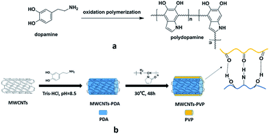 |
| | Fig. 1 Schematic illustration of (a) the polymerization of dopamine, and (b) preparation of the PVP-modified MWCNTs. | |
2.3 Fabrication of hybrid membranes
The hybrid membranes were prepared by the phase inversion precipitation method. Briefly, PES was added to a solution of DMF in which MWCNTs had been fully dispersed, with the PES constituting 17 wt% of the total mixture. The mixture was subsequently continuously stirred using a magnetic stirrer until the polymer had completely dissolved. As a pore former, 5 wt% PVP was added to the mixture and the stirring was continued for 1 h. To remove the bubbles, the mixture was heated to 50 °C and maintained at the temperature for a regular time. The final solution was thereafter cooled to room temperature and cast on a clean glass plate to a height of 200 μm using a cast knife. After exposure to air for 30 s to reduce the defects due to human factors, the casting solution was immersed in the coagulation for more than 24 h to remove the residual solvent and pore former. The formed hybrid membranes were then stored in a wet environment before being used for ultrafiltration testing. Seven samples of the hybrid membranes were prepared using different types and amounts of MWCNTs and were labelled M0, M1, M2, M3, M4, M5, and M6, respectively. Table 1 presents the concrete compositions of the casting solutions used to prepare the different samples.
Table 1 Compositions of the casting solutions used to prepare the membrane samples
| Membrane |
PES (%) |
PVP (%) |
DMF (%) |
Additive/content related to the weight of the polymer (%) |
| M0 |
17 |
5 |
78 |
0 |
| M1 |
17 |
5 |
78 |
MWCNTs-PDA/0.05 |
| M2 |
17 |
5 |
78 |
MWCNTs-PDA/0.1 |
| M3 |
17 |
5 |
78 |
MWCNTs-PDA/0.2 |
| M4 |
17 |
5 |
78 |
MWCNTs-PVP/0.05 |
| M5 |
17 |
5 |
78 |
MWCNTs-PVP/0.1 |
| M6 |
17 |
5 |
78 |
MWCNTs-PVP/0.2 |
2.4 Characterization
2.4.1 Characterization of MWCNTs. Fourier transform infrared spectroscopy (FTIR) was used to confirm the coating of PDA and PVP on the MWCNTs. The FTIR spectra was recorded using a Nicolet Impact 410 Fourier transform infrared spectrophotometer within the range of 4000–400 cm−1. An X-ray photoelectron spectrometer (XPS, ESCALAB 250) with a monochromic source (Al Kα line, 1486.6 eV) was used to detect the elemental changes on the MWCNTs surface. The charging shift of the spectrometer was corrected using a binding energy of C (1s) at 284.6 eV. The morphologies of the raw MWCNTs and polymer-modified MWCNTs were observed by a transmission electron microscope (TEM, PHI-1600). For this purpose, the respective MWCNTs were sonicated in deionized water and the suspensions were dropped onto a carbon-coated copper grid, and subsequently dried at room temperature. The weight fraction of PVP coated onto the MWCNTs was determined using Perkin Elmer Pyris 1 TGA analyzer and the thermal analysis was conducted at a heating rate of 20 °C min−1 to a maximum temperature of 800 °C in a nitrogen atmosphere.
2.4.2 Membrane hydrophilicity, porosity and mean pore size. The hydrophilicity of each membrane surface was examined by measuring the water contact angle (WCA). The static water contact angle of the membrane surface was measured by a POWEREACHJC2002C2 contact angle meter at room temperature. A small water droplet was carefully dropped onto the membrane surface and its status was immediately recorded by a digital microscope. To reduce the experimental errors, each sample was tested at least five times and the obtained results were averaged.The porosity of each hybrid membrane was calculated as described by Zhang et al.27 The membrane was cut into a (2 × 2 cm) square and immersed in distilled water for 24 h. The wet membrane was then weighed after wiping the water from its surfaces. It was subsequently placed in an air-circulating oven at 50 °C until its weight stabilized. The weight of the dry membrane was recorded and its porosity was calculated using the following equation:
| |
 | (1) |
where
ε is the membrane porosity,
Ww and
Wd are respectively the weights of the wet and dry membranes,
A is the effective area of the membrane (cm
2),
l is the membrane thickness (cm), and
ρ is the density of pure water (g cm
−3). The membrane mean pore radius (
rm) was determined by the Guerout–Elford–Ferry equation (
eqn (2)) on the basis of the pure water flux and porosity data:
28| |
 | (2) |
Where
η is the water viscosity (8.9 × 10
−4 Pa s),
Q is the volume of permeate pure water per unit time (m
3 s
−1) and Δ
P is the operation pressure (0.1 MPa).
2.4.3 Membrane morphology. To understand the morphology changes after the mixing of the various MWCNTs, field emission scanning electron microscopy (FESEM) was employed. The images of the membrane morphologies were recorded by an FEI Nova NanoSEM 450 microscope. The membrane pieces were fractured in liquid nitrogen and the fracture sections were coated with gold. The skin-layer and sublayer were then observed through the cross-sectional images. The distributions of the MWCNTs on the membrane surface and cross-section were also investigated.
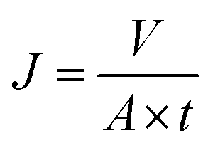
2.4.4 Ultrafiltration experiments. A cross-flow filtration unit supplied by Tianjin Polytechnic University was used to test the permeability and antifouling characteristics of the hybrid membranes, which each had an effective area of 7.1 cm2. The procedure of the ultrafiltration process was as follows. The membrane was first pressed for 30 min at 0.15 MPa to form a compact structure. The pressure was then reduced to 0.10 MPa and a pure water flux test was conducted for 60 min. The permeation flux was calculated as follows:| |
 | (3) |
where J is the permeation flux (L m−2 h), V is the volume of the penetrants (L), A is the area of the membrane (m2), and t is the filtration time (h).Subsequently, the BSA solution (1 mg ml−1, pH = 7.4) was used to replace the pure water to measure the antifouling capacity of the membrane.10,17 This process lasted for 120 min. The protein rejection (R) was determined using the following equation:
| |
 | (4) |
where
Cf and
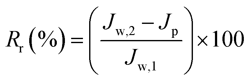
Cp are respectively the BSA concentrations of the feed and permeate. The BSA concentrations of the feed and permeate were measured by a UV2501-PC spectrophotometer at 278 nm. The contaminated membrane was then cleaned using only distilled water, and then another 60 min pure water test was conducted. To clearly analyze the antifouling capacity of the membrane, some parameters such as the flux recovery ratio (FRR), total fouling ratio (
Rt), reversible fouling ratio (
Rr), and irreversible fouling ratio (
Rir) were considered. They were calculated using following equations:
29| |
 | (5) |
| |
 | (6) |
| |
 | (7) |
where
Jw,1 and
Jw,2 are respectively the initial and contaminated-membrane water fluxes, and
Jp is the protein flux. All ultrafiltration results in this manuscript are the average values obtained by three measurements from three membrane samples.
3 Results and discussion
3.1 Modification of MWCNTs
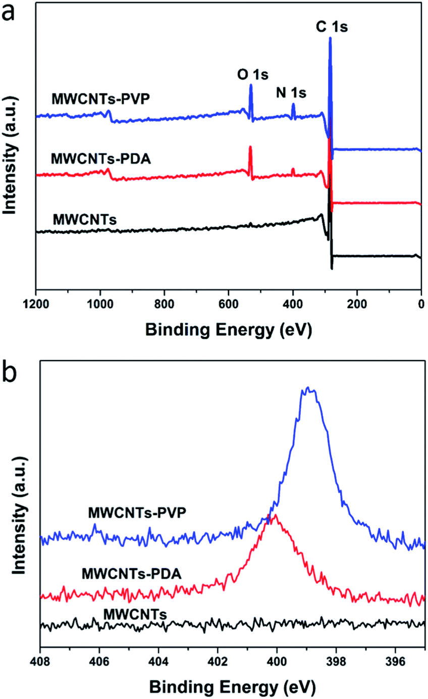
The typical FTIR spectra for the three types of MWCNTs is shown in Fig. 2, where the distinctions between the raw and modified MWCNTs can be clearly observed. The new peaks at 1637 and 1512 cm−1 in the spectra of MWCNTs-PDA are attributed to the resonance vibrations of the C![[double bond, length as m-dash]](https://www.rsc.org/images/entities/char_e001.gif) C aromatic rings and the bending vibrations of N–H,30,31 indicating successful generation and coating of the PDA on the MWCNTs. After further modification of the MWCNTs with PVP, the new peak that appeared at 1650 cm−1 is attributed to the stretching of CO in the pyrrolidone ring of PVP. This observation further confirms the adsorption of PVP by PDA. XPS was used to estimate the quantities of adsorbed PDA and PVP, the results of which are shown in Fig. 3. In the case of the raw MWCNTs, C 1s is observed at 284 eV, as well as trace amounts of oxygen, which originates from the residual catalyst used for the preparation of the nanotubes. Further, the appearance of new peaks in the spectra of MWCNTs-PDA at 400 eV (N 1s) and 531 eV (O 1s) demonstrates the successful immobilization of PDA on the MWCNTs. A comparison of the spectra of MWCNTs-PDA and MWCNT-PVP reveals significant increase in the signal intensity of N 1s in the latter, further confirming the adsorption of PVP by MWCNTs-PDA because the amount of N in PVP is greater than that in PDA. The specific elemental compositions of the samples are given in Table 2. TGA measurements were carried out to calculate the content of PVP in MWCNTs-PVP as shown in Fig. 4, and about 8.7 wt% PVP was measured. The initial thermal decompositions of MWCNTs-PDA and MWCNTs-PVP are due to the decomposition of PDA.32
C aromatic rings and the bending vibrations of N–H,30,31 indicating successful generation and coating of the PDA on the MWCNTs. After further modification of the MWCNTs with PVP, the new peak that appeared at 1650 cm−1 is attributed to the stretching of CO in the pyrrolidone ring of PVP. This observation further confirms the adsorption of PVP by PDA. XPS was used to estimate the quantities of adsorbed PDA and PVP, the results of which are shown in Fig. 3. In the case of the raw MWCNTs, C 1s is observed at 284 eV, as well as trace amounts of oxygen, which originates from the residual catalyst used for the preparation of the nanotubes. Further, the appearance of new peaks in the spectra of MWCNTs-PDA at 400 eV (N 1s) and 531 eV (O 1s) demonstrates the successful immobilization of PDA on the MWCNTs. A comparison of the spectra of MWCNTs-PDA and MWCNT-PVP reveals significant increase in the signal intensity of N 1s in the latter, further confirming the adsorption of PVP by MWCNTs-PDA because the amount of N in PVP is greater than that in PDA. The specific elemental compositions of the samples are given in Table 2. TGA measurements were carried out to calculate the content of PVP in MWCNTs-PVP as shown in Fig. 4, and about 8.7 wt% PVP was measured. The initial thermal decompositions of MWCNTs-PDA and MWCNTs-PVP are due to the decomposition of PDA.32
 |
| | Fig. 2 FTIR spectra of the raw and polymer-modified MWCNTs. | |
 |
| | Fig. 3 Results of XPS (a) wide scan; and (b) N 1s of the surface of the MWCNTs before and after modification. | |
Table 2 Surface elemental compositions of the MWCNTs determined by XPS
| Sample |
C (%) |
O (%) |
N (%) |
| MWCNTs |
98.38 |
1.62 |
0 |
| MWCNTs-PDA |
83.78 |
11.22 |
5.01 |
| MWCNTs-PVP |
83.27 |
10.61 |
6.12 |
 |
| | Fig. 4 TGA curves of PVP, MWCNTs-PDA and MWCNTs-PVP. | |
The TEM results show the morphologies of the raw and modified MWCNTs. The change in the morphology of the MWCNTs is evaluated by measuring the diameters of the nanotubes before and after modification. As shown in Fig. 5, the raw MWCNTs have an outer diameter of about 10–20 nm, and their surfaces are relatively smooth. However, the diameters of MWCNTs-PDA is increased to approximately 25 nm, which indicates that PDA have successfully formed on the surface of the MWCNTs. Similar phenomena appeared in other reported literature.10 Moreover, the PVP coating produces a sharp increase in the diameter of the nanotubes to 30–35 nm. However, it is observed that the diameter of the modified MWCNTs is not completely uniform, attributable to the similar trend of the raw MWCNTs and the inhomogeneous polymer cladding.
 |
| | Fig. 5 TEM images of (a) MWCNTs, (b) MWCNTs-PDA, and (c) MWCNTs-PVP. | |
3.2 Dispersion of MWCNTs
To investigate the changes in the chemical properties of the modified MWCNTs and their dispersion in water, we conducted the following experiment. As shown in Fig. 6a, three types of MWCNTs were sonicated for 1 h in water, and it was observed that the raw MWCNTs could not be uniformly dispersed in water. Conversely, MWCNTs-PDA and MWCNTs-PVP were stably dispersed in water. However, after 24 h, the MWCNTs-PDA gradually precipitated to the bottom, whereas the MWCNTs-PVP maintained their stable status for days (see Fig. 6b). This indicated that the PVP-modified MWCNTs possessed the best dispersity. Afterwards, the same volume of toluene was added to the three above-mentioned suspensions. As shown in Fig. 6c, the raw MWCNTs completely migrated to the toluene, while a portion of the MWCNTs-PDA migrated to the toluene and the interface of the suspension. However, in the case of the MWCNTs-PVP, it remained entirely dispersed in water. These observations demonstrated the superior hydrophilicity of the PVP-modified MWCNTs compared with the raw and PDA-modified MWCNTs.33 This property is extremely important for the antifouling ability and permeability of hybrid membranes.
 |
| | Fig. 6 Three types of MWCNTs: (a) sonicated dispersion in water for 1 h; (b) after 24 h; (c) dispersion of MWCNTs in a mixture of toluene and water. From left to right, the beakers in each panel correspond to raw MWCNTs, PDA-modified MWCNTs, and PVP-modified MWCNTs, respectively. | |
3.3 Membrane hydrophilicity
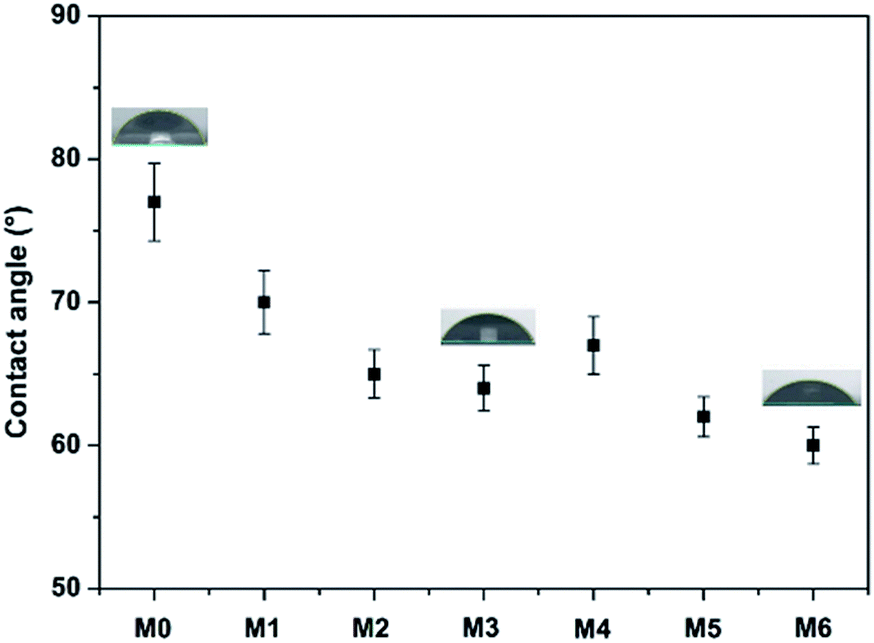
Hydrophilicity is an important determinant of the antifouling properties and permeability of a separation membrane. The more hydrophilic a membrane is, the easier water would wet its surface.34 In addition, a hydration layer is more easily formed on a hydrophilic membrane surface, and this can be used to effectively prevent the adsorption of pollutants. Generally, the water contact angle is used to evaluate the hydrophilicity of the membranes, with a lower water contact angle indicating higher hydrophilicity. The water contact angle for all the membranes considered in the present study are given in Fig. 7. As can be observed from the figure, the hybrid membranes containing polymer-modified MWCNTs exhibit smaller contact angle than the pristine PES membrane. This is because the hydrophilic polymer-modified MWCNTs tend to migrate spontaneously to the top surface to reduce their interface energy. In addition, the PES/MWCNTs-PVP hybrid membranes exhibit smaller contact angles compared with the PES/MWCNTs-PDA hybrid membranes owing to the stronger water adsorption capacity of PVP.35 The hybrid membrane with 0.2% MWCNTs-PVP produces the smallest contact angle, which represents significant reduction compared with that of the pristine PES membrane.
 |
| | Fig. 7 Water contact angles of all the prepared membranes. | |
3.4 Porosity and mean pore size
The membrane permeability is significantly affected by the membrane porosity and pore size, which also varies significantly with the type and amount of MWCNTs. The accurate porosity and mean pore size of the hybrid membranes are given in Table 3. As can be observed from the table, the porosity and pore size increase with increasing amount of MWCNTs, with MWCNTs-PVP increasing the membrane porosity more effectively compared with MWCNTs-PDA. This can be related to different thermodynamic behaviors. The hydrophilic additive accelerates the rate of exchange between the solvent and non-solvent during the phase separation process, and the favoured water diffusion promotes the formation of lean polymer phase points, which acts as pore formation agent.10,36
Table 3 Bulk porosities and rejections of all the prepared membranes
| Membrane |
Porosity (%) |
Average diameter (nm) |
Rejection (%) |
| M0 |
42.3 ± 1.3 |
31.1 ± 1.2 |
97.0 |
| M1 |
45.6 ± 1.5 |
34.4 ± 1.6 |
96.1 |
| M2 |
51.8 ± 1.8 |
36.6 ± 1.8 |
95.6 |
| M3 |
64.4 ± 2.6 |
39.4 ± 2.1 |
94.5 |
| M4 |
49.4 ± 1.5 |
35.5 ± 1.9 |
96.7 |
| M5 |
57.5 ± 2.4 |
38.3 ± 2.1 |
96.4 |
| M6 |
70.8 ± 3.0 |
40.3 ± 2.2 |
95.1 |
3.5 Membrane morphology
To investigate the effects of the different types and utilized amounts of MWCNTs on the membrane morphology, FESEM was used to observe the surface and cross-sectional morphologies of all the prepared membranes. The representative FESEM images of the membranes are shown in Fig. 8, which reveals a typical asymmetric structure with a dense skin layer and porous supporting layer. It is well known that an ultrafiltration membrane with a dense skin layer is able to reject protein, while a porous sublayer impacts the mechanical strength of the membrane.28 The surface FESEM images reveal no significant defect in the membranes, explaining the observation of no significant change in the BSA rejection rate. Furthermore, some of the MWCNTs can be observed on the surface and in the pore walls of M2 and M5, with the amount of observable MWCNTs higher in the latter membrane. This can be explained by the fact that the more hydrophilic PVP-modified MWCNTs more easily migrated to the membrane surface compared with the PDA-modified MWCNTs during the phase inversion process.25 The cross-sectional images reveal a structure consisting of finger-like pores and macrovoids at the bottom. The finger-like pores, which are advantageous to water transport, are broader and more developed in the hybrid membranes compared with the pristine PES membrane. It is noteworthy that a hydrophilic additive affects the thermodynamic and dynamic behaviors of a membrane during its formation. The additive may facilitate phase inversion, which enhances macrovoid formation.37,38 Higher magnification images of the present membranes reveal numerous micropores in the walls of the finger-like pores-a structure that is conducive to the formation of water channels.
 |
| | Fig. 8 Surface and cross-sectional morphologies of membranes containing different types and amounts of MWCNTs. | |
Fig. 9 compares the morphologies of the membranes containing different amounts of MWCNTs-PVP. The increased amount of MWCNTs also facilitates the development of the supporting layer. MWCNTs are hardly discernible on the surface of M4 due to the low MWCNTs content. With increasing MWCNTs content, more MWCNTs can be observed, as in M5 and M6. In the case of M6, some of the MWCNTs are intertwined, which is disadvantageous to the full development of the hydrophilic effect of PVP. The membrane surfaces have more pores and became rougher with increasing MWCNTs content, which is unfavorable for the improvement of antifouling properties of the hybrid membranes.
 |
| | Fig. 9 Surface and cross-sectional morphologies of membranes containing different amounts of MWCNTs-PVP. | |
3.6 Membrane ultrafiltration performance
3.6.1 Permeation properties. The permeability of a membrane is determined by the morphology, porosity, and hydrophilicity.39 A higher-porosity and more hydrophilic membrane exhibits lower penetration resistance. The pure water fluxes of the hybrid membranes are shown in Fig. 10. As can be seen, the pristine PES membrane have the lowest water flux of 136 L m−2 h−1. In addition, the water flux increases with increasing amount of MWCNTs in the hybrid membranes. This is because the hydrophilic additive increased the bulk porosity during the membrane formation process. However, the degree of enhancement is limited, apparently due to the MWCNTs aggregation counteracting pore formation to some extent.10,37,40 It is clear that the hybrid membranes containing MWCNTs-PVP exhibit a higher flux than those containing MWCNTs-PDA. This could be caused by the more uniform dispersion of MWCNTs-PVP in the membrane matrix. The measured water contact angles also show that the hydrophilicity of the MWCNTs-PVP modified membranes is superior to that of the MWCNTs-PDA modified membranes. Among all the membranes, M6 exhibits the best pure water flux of 290 L m−2 h−1, which is more than twice that of the pristine PES membrane. As can be observed from Fig. 9, the tendency of the protein solution flux of the membranes is similar to that of the water flux. The prepared membranes exhibit very high protein retention, as indicated in Table 3.
 |
| | Fig. 10 Pure water flux (left) and protein flux (right) of prepared membranes. | |
3.6.2 Antifouling performance. In practical applications, a membrane tends to be fouled by protein, dye molecules, bacteria, etc. The membrane fouling can increase the membrane permeation resistance, resulting in serious flux attenuation. Generally, membrane fouling can be categorized as reversible fouling and irreversible fouling. Forceful adsorption to the membrane surface and inner pores causes irreversible fouling, namely, one that is difficult to rectify. Conversely, the case of, for example, protein adhering lightly to the surface of the membrane is regarded as reversible fouling and can be rectified by simple hydraulic cleaning.17,41 The flux recovery ratio is an important parameter that is used to evaluate the reusability of the ultrafiltration membranes. The fouling parameters and flux recovery ratios of all the prepared membranes in the present study are shown in Fig. 11. All the hybrid membranes exhibit lower Rt and higher Rr compared with the pristine PES membrane, indicating that the former had superior fouling resistance. This is because PDA and PVP induce the formation of a tightly bound layer of water molecules, which inhibites the adsorption of protein. With increasing amount of MWCNTs, the antifouling ability of the hybrid membranes initially increases, and then decreases. The reason is that the increased membrane surface roughness and mean pore size due to the MWCNTs clusters directly diminished the antifouling ability.17,40 Hybrid membrane M5, which contains 0.1% MWCNTs-PVP, exhibits the lowest Rt of 64.7% and Rir of 4.8%. Most of the protein that is adsorbed to its surface could thus be detached. The flux recovery ratio (FRR) values of the hybrid membranes are strikingly enhanced compared with that of the pristine PES membrane due to the enhanced hydrophilicity of the former. M5 exhibits the most outstanding FRR of 95%.
 |
| | Fig. 11 (a) Fouling parameters and (b) flux recovery ratios of all the fabricated membranes. | |
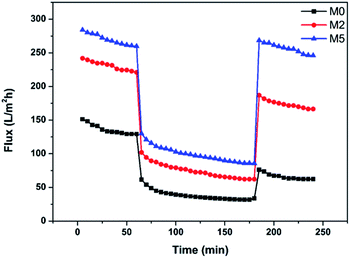
Fig. 12 shows the variation of the fluxes of M0, M2, and M5 during the entire ultrafiltration process. At the beginning of the test of each membrane, there was a slight decrease of the flux due to compression of the membrane structure,42 with the flux tending to stabilize gradually with time. When the pure water was changed to protein solution, there was an instantaneous and significant decrease of the flux due to the formation of a filter-cake layer through protein deposition. After the membrane was cleaned, the water flux was recovered to varying extents. It is evident from the three curves in Fig. 12 that hybrid membrane M5 exhibits the best overall performance, attributable to its favorable membrane morphology, porosity, and hydrophilicity.
 |
| | Fig. 12 Variation of the fluxes of membranes M0, M2, and M5 during the entire filtration process. | |
4 Conclusions
PDA- and PVP-modified MWCNTs were prepared and respectively integrated into the matrix of PES membrane. The effects of the two modification polymers and different relative amounts and types of MWCNTs on the separation membrane were investigated. Following are the conclusions drawn from the study. Firstly, the incorporation of the two types of modified MWCNTs improved the membrane porosity and hydrophilicity, as well as the permeability and antifouling properties, without any visible decrease in protein retention. In addition, the hydration ability of PVP was stronger than that of PDA, and the PVP-modified MWCNTs thus had a more positive impact on the membrane performance. However, the high MWCNTs content could increase the mean pore size and surface roughness of the membranes, which is unfavorable for antifouling properties. The hybrid membrane containing 0.1% PVP-modified MWCNTs exhibited the optimal comprehensive performance, including a flux recovery rate of 95% and pure water flux of 270 L m−2 h−1, which was twice that of the pristine PES membrane.
We thus successfully implemented a facile and versatile method for fabricating MWCNTs with favorable hydrophilicity and dispersity for incorporation in the membranes. The ultrafiltration performance of the membranes was significantly improved by the integration of the PVP-modified MWCNTs. The good compatibility of PVP with different polymer matrixes promises to make the proposed functionalization of MWCNTs applicable to various separation membrane substrates for improved performance.
Acknowledgements
The authors appreciate the financial support of the National Nature Science Foundation of China (51573070), the Jilin Provincial Science and Technology Development Project of China (20150204001GX), and the Jilin Provincial Economic Structure Strategic Adjustment Guide Fund Special Project (High Technology Industry) (2015Y045).
Notes and references
- G. Kwon, A. K. Kota, Y. Li, A. Sohani, J. M. Mabry and A. Tuteja, Adv. Mater., 2012, 24, 3666–3671 CrossRef CAS PubMed.
- Q. Li, Q. Bi, H. H. Lin, L. X. Bian and X. L. Wang, J. Membr. Sci., 2013, 427, 155–167 CrossRef CAS.
- M. Radjabian and V. Abetz, Adv. Mater., 2015, 27, 352–355 CrossRef CAS PubMed.
- C. Deng, Q. G. Zhang, G. L. Han, Y. Gong, A. M. Zhu and Q. L. Liu, Nanoscale, 2013, 5, 11028–11034 RSC.
- Y. F. Zhao, L. P. Zhu, Z. Yi, B. K. Zhu and Y. Y. Xu, J. Membr. Sci., 2014, 470, 148–158 CrossRef CAS.
- D. Rana and T. Matsuura, Chem. Rev., 2010, 110, 2448–2471 CrossRef CAS PubMed.
- F. Xiao, P. Xiao, W. J. Zhang and D. S. Wang, J. Membr. Sci., 2013, 447, 144–152 CrossRef CAS.
- M. Kumar, D. McGlade and J. Lawler, RSC Adv., 2014, 4, 21699–21711 RSC.
- Y. F. Chen, Y. T. Zhang, H. Q. Zhang, J. D. Liu and C. H. Song, Chem. Eng. J., 2013, 228, 12–20 CrossRef CAS.
- R. S. Hebbar, A. M. Isloor, K. Ananda and A. F. Ismail, J. Mater. Chem. A, 2016, 4, 764–774 CAS.
- X. Huang, J. Zhang, W. P. Wang, Y. D. Liu, Z. B. Zhang, L. Li and W. L. Fan, RSC Adv., 2015, 5, 18258–18266 RSC.
- Y. B. Gu, R. M. Dorin and U. Wiesner, Nano Lett., 2013, 13, 5323–5328 CrossRef CAS PubMed.
- H. J. Kim, M. Y. Lim, K. H. Jung, D. G. Kim and J. C. Lee, J. Mater. Chem. A, 2015, 3, 6798–6809 CAS.
- Y. Z. Liao, D. G. Yu, X. Wang, W. Chain, X. G. Li, E. M. V. Hoek and R. B. Kaner, Nanoscale, 2013, 5, 3856–3862 RSC.
- S. J. Gao, Z. Shi, W. B. Zhang, F. Zhang and J. Jin, ACS Nano, 2014, 8, 6344–6352 CrossRef CAS PubMed.
- C. F. D. Lannoy, E. Soyer and M. R. Wiesner, J. Membr. Sci., 2013, 447, 395–402 CrossRef.
- P. Daraei, S. S. Madaeni, N. Ghaemi, M. A. Khadivi, B. Astinchap and R. Moradian, J. Membr. Sci., 2013, 444, 184–191 CrossRef CAS.
- T. Y. Liu, H. G. Yuan, Q. Li, Y. H. Tang, Q. Zhang, W. Z. Qian, B. V. Bruggen and X. L. Wang, ACS Nano, 2015, 9, 7488–7496 CrossRef CAS PubMed.
- J. H. Choi, J. Jegal and W. N. Kim, J. Membr. Sci., 2006, 284, 406–415 CrossRef CAS.
- X. Zhao, J. Ma, Z. Wang, G. Wen, J. Jiang, F. Shi and L. Sheng, Desalination, 2012, 303, 29–38 CrossRef CAS.
- L. M. Bai, H. Liang, J. Crittenden, F. S. Qu, A. Ding, J. Ma, X. Du, S. D. Guo and G. B. Li, J.
Membr. Sci., 2015, 492, 400–411 CrossRef CAS.
- H. Lee, S. M. Dellatore, W. M. Miller and P. B. Messersmith, Science, 2007, 318, 426–430 CrossRef CAS PubMed.
- X. C. Liu, G. C. Wang, R. P. Liang, L. Shi and J. D. Qiu, J. Mater. Chem. A, 2013, 1, 3945–3953 CAS.
- H. Y. Wang, E. Q. Wang, Z. J. Liu, D. Gao, R. X. Yuan, L. Y. Sun and Y. J. Zhu, J. Mater. Chem. A, 2015, 3, 266–273 CAS.
- M. P. Sun, Y. L. Su, C. X. Mu and Z. Y. Jiang, Ind. Eng. Chem. Res., 2010, 49, 790–796 CrossRef CAS.
- T. Xiang, W. W. Yue, R. Wang, S. Liang, S. D. Sun and C. S. Zhao, Colloids Surf., B, 2013, 110, 15–21 CrossRef CAS PubMed.
- G. L. Zhang, S. F. Lu, L. Zhang, Q. Meng, C. Shen and J. W. Zhang, J. Membr. Sci., 2013, 436, 163–173 CrossRef CAS.
- J. Zhang, Z. W. Xu, W. Mai, C. Y. Min, B. M. Zhou, M. J. Shan, Y. L. Li, C. Y. Yang, Z. Wang and X. M. Qian, J. Mater. Chem. A., 2013, 1, 3101–3111 CAS.
- D. G. Kim, H. Kang, S. Han and J. C. Lee, J. Mater. Chem., 2012, 22, 8654–8661 RSC.
- Y. H. Xiang, F. Liu and L. X. Xue, J. Membr. Sci., 2015, 476, 321–329 CrossRef CAS.
- H. Y. Shi, L. X. Xue, A. L. Gao, Y. Y. Fu, Q. B. Zhou and L. j. Zhu, J. Membr. Sci., 2016, 498, 39–47 CrossRef CAS.
- W. P. Liu, Y. F. Li, X. X. Meng, G. H. Liu, S. Hu, F. S. Pan, H. Wu, Z. Y. Jiang, B. Y. Wang, Z. X. Li and X. Z. Cao, J. Mater. Chem. A, 2013, 1, 3713–3723 CAS.
- J. N. Shen, C. C. Yu, H. M. Ruan, C. J. Gao and B. V. Bruggen, J. Membr. Sci., 2013, 442, 18–26 CrossRef CAS.
- V. Vatanpour, S. S. Madaeni, R. Moradian, S. Zinadini and B. Astinchap, J. Membr. Sci., 2011, 375, 284–294 CrossRef CAS.
- J. H. Jiang, L. P. Zhu, L. J. Zhu, H. T. Zhang, B. K. Zhu and Y. Y. Xu, ACS Appl. Mater. Interfaces, 2013, 5, 12895–12904 CAS.
- M. Kumar and M. Ulbricht, RSC Adv., 2013, 3, 12190–12203 RSC.
- M. Kumar and M. Ulbricht, J. Membr. Sci., 2013, 448, 62–73 CrossRef CAS.
- S. Majeed, D. Fierro, K. Buhr, J. Wind, B. Du, A. B. Fierro and V. Abetz, J. Membr. Sci., 2012, 403–404, 101–109 CrossRef CAS.
- P. Le-Clech, V. Chen and T. A. G. Fane, J. Membr. Sci., 2006, 284, 17–53 CrossRef CAS.
- V. Vatanpour, M. Esmaeili and M. H. D. A. Farahani, J. Membr. Sci., 2014, 466, 70–81 CrossRef CAS.
- Y. Liu, S. L. Zhang and G. B. Wang, Desalination, 2013, 316, 127–136 CrossRef CAS.
- S. Zhao, Z. Wang, X. Wei, B. R. Zhao, J. X. Wang, S. B. Yang and S. C. Wang, Ind. Eng. Chem. Res., 2012, 51, 4661–4672 CrossRef CAS.
|
| This journal is © The Royal Society of Chemistry 2017 |
Click here to see how this site uses Cookies. View our privacy policy here. 
 Open Access Article
 This Open Access Article is licensed under a
  ,
Shuling Zhang,
Yinlong Du,
Yaning Lu,
Ruiqi Na,
Yongfeng Mu and
Yunhe Zhang
,
Shuling Zhang,
Yinlong Du,
Yaning Lu,
Ruiqi Na,
Yongfeng Mu and
Yunhe Zhang