 Open Access Article
Imidazolium-functionalized anion exchange membranes using poly(ether sulfone)s as macrocrosslinkers for fuel cells†
Xiao Ling Huang,
Chen Xiao Lin,
En Ning Hu,
Faizal Soyekwo,
Qiu Gen Zhang ,
Ai Mei Zhu and
Qing Lin Liu
 *
*
Fujian Provincial Key Laboratory of Theoretical and Computational Chemistry, Department of Chemical & Biochemical Engineering, College of Chemistry & Chemical Engineering, Xiamen University, Xiamen 361005, China. E-mail: qlliu@xmu.edu.cn
First published on 23rd May 2017
Abstract
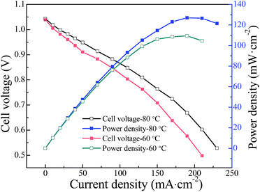
A series of novel macrocrosslinked imidazolium-based anion exchange membranes (AEMs) with high hydroxide conductivity and dimensional stability were synthesized by crosslinking a poly(vinyl imidazole) ionic liquid with bromide-terminated poly(ether sulfone) via Menshutkin reaction. Fourier transform infrared (FT-IR) and energy dispersive spectrometry (EDS) were used to confirm the chemical structure and successful crosslinking of the AEMs. The contiguous imidazolium cations along the polyolefin backbone are found to aggregate and connect to form continuous hydroxide transport microchannels by the introduction of long hydrophobic poly(ether sulfone) chain as evidenced by atomic force microscopy (AFM). As a consequence, a high hydroxide conductivity of 78.5 mS cm−1 was achieved for the crosslinked PES/PVIIL-0.4 membrane at 80 °C. A single cell test using the PES/PVIIL-0.4 membrane exhibits an open circuit voltage of 1.039 V and peak power density of 109.5 mW cm−2 at the current density of 190 mA cm−2 at 60 °C. This newly developed strategy holds great promise to prevent fuel crossover in alkaline fuel cells.
Introduction
Proton exchange membrane fuel cells (PEMFCs) have currently drawn wide attention in the new energy generation field because of their higher energy density, higher energy conversion efficiency and lower environmental pollution than traditional fossil fuels.1–3 However, the extensive commercialization of PEMFCs still faces some critical challenges particularly emanating from the intensive dependence on precious noble metal based catalysts, sluggish fuel oxidation/oxygen reduction kinetics and the limited long-term service time of proton exchange membranes (PEMs).4,5 Furthermore, the most commonly used Nafion membranes readily suffer from issues of environmental incompatibility, excessive fuel permeation and declining proton conductivity at low relative humidity.6–8 This reduces not only the fuel use efficiency but also the open circuit potential of PEMFCs, thus lowering their overall performance.9 To overcome these challenges, much more attention is focused on the development of anion exchange membrane fuel cells (AEMFCs) owing to their faster electrokinetics, higher catalyst resistance to carbon monoxide and wider choice of non-precious metal catalysts (e.g. Ni, Co and Ag), which significantly reduces the cost of fuel cells.10–14As a critical component in AEMFCs, anion exchange membranes (AEMs) play a role in separating the fuel and oxygen and simultaneously transferring hydroxide ions. Different from PEMs, the migration of hydroxide ions inside AEMs starts from the anode to cathode, and is opposite to the diffusion direction of fuel, dramatically preventing the fuel crossover of AEMs and facilitating the effective utilization of fuels.15 However, the inherent lower mobility of OH− (2.69) than H+ (4.76) at room temperature (RT) in an extremely dilute solution is an impediment to improve the conductivity of AEMs to the level of PEMs.16 This makes it particularly necessary to design efficient polymer structures with high ionic exchange capacity (IEC).17–19 Paradoxically, many more hydroxide conduction groups introduced to the polymer electrolytes usually result in high water uptake, excessive membrane swelling and poor mechanical stability.20,21 This would potentially release catalyst layers from both sides of electrodes and eventually upset the fabrication of membrane electrode assembly (MEA).22
Crosslinking is used as one of the most efficient and promising methods to address this challenge. This technique can simultaneously achieve good physical properties and high conductivity. For example, Lee and co-workers23,24 reported the preparation of end-group crosslinked PEMs and AEMs with unusual morphological transformation using thermal alkyne trimerization. The ionic groups were found to rearrange to improve conductivity efficiency and the dimensional stability with a lower hydration number. However, the conventional crosslinked AEMs are normally prepared at the cost of consuming functional halomethyl groups for producing crosslinked structure thus reducing the content of functional ionic groups.25,26 In order to get rid of the drawbacks from the traditional crosslinked technique, the development of novel crosslinked membranes through imidazolium or quaternization reaction is becoming more attractive.27–30 For example, Wang et al.31 reported that crosslinked poly(ether ether ketone) AEMs prepared using 1,4-diazabicyclo-2,2,2-octane as both the crosslinking and quaternization reagent achieved low swelling ratio of 48.2% at 60 °C but high conductivity of 33.4 mS cm−1 at 25 °C. On the other hand, the development of a membrane with efficient ion conductive channels is another strategy to enhance the mechanical properties while maintaining high hydroxide conductivity because of the microphase separation morphology. The comb-shaped32,33 and block34,35 AEMs are found to favor the formation of ionic transport channels due to the aggregation of hydrophilic ionic moieties. For example, Li et al. demonstrated a series of comb-shaped CyDx cationic copolymers with varied length of alkyl side chains.33 The C16Dx membrane with the longest hexadecyl chain achieved the highest conductivity due to its unique architecture induced by self-assembly of hydrophilic cationic groups and long hydrophobic alkyl side chains. Moreover, longer hydrophobic polymer chains between the hydrophilic pendent domains promote the gathering of hydrophobic segments.16 It is thus apparent that good molecular structural design of hydrophilic/hydrophobic microphase separation morphology tends to improve the efficiency of OH− hopping conduction in AEMs.36
In this work, a new kind of macrocrosslinked imidazolium-based anion exchange membranes (AEMs) was prepared via imidazolium reaction. Poly(vinyl imidazole) (PVI) was chosen as the main chain material particularly due to: (1) abundant functional sites, (2) facile synthesis, and (3) higher thermal stability than the conventional quaternary alkyl ammonium cations.8 Moreover, the inherent inadequate alkaline stability of AEMs containing imidazoliums can be effectively enhanced via crosslinking.27,37 PES is tailored-synthesized as a macrocrosslinker because of the excellent mechanical property and thermal stability.29 The dense imidazolium groups of PVIIL facilitate the aggregation of ionic exchange moieties5,38 and the Br-PES-Br with long hydrophobic chain further promotes the phase separation of hydrophilic imidazolium from hydrophobic PES.36 By varying the feeding weight ratio of Br-PES-Br to PVIIL, a series of imidazolium-based AEMs with excellent microstructure were prepared and characterized. Furthermore, the properties of the as-synthesized membranes including hydroxide conductivity, water uptake, swelling ratio, mechanical properties and alkaline stability were investigated.
Experimental section
Materials and reagents
1-Bromobutane (98%, Sinopharm Chemical Reagent Co., Ltd, China), bis(4-fluorophenyl)sulfone (FPS) (99%, TCI, Japan), 4,4′-(hexafluoroisopropylidene)diphenol (BPHF) (98%, Aladdin, China), α,α′-dibromo-p-xylene (98%, TCI, Japan) were used as received. 1-Vinyl imidazole (VIm) (99.0%, Aladdin, China) was purified via vacuum distillation. Azodiisobutyronitrile (AIBN) (99.0%, Tianjin Guangfu Fine Chemical Research Institute, China) was recrystallized from methanol prior to use. Toluene and N,N-dimethylacetamide (DMAc) (99.8%, Aladdin, China) were dehydrated by stirring over CaH2 for 24 h and then distilling under reduced pressure. All other reagents were available from Sinopharm Chemical Reagent Co., Ltd and used without further purification.Preparation of anion exchange membranes
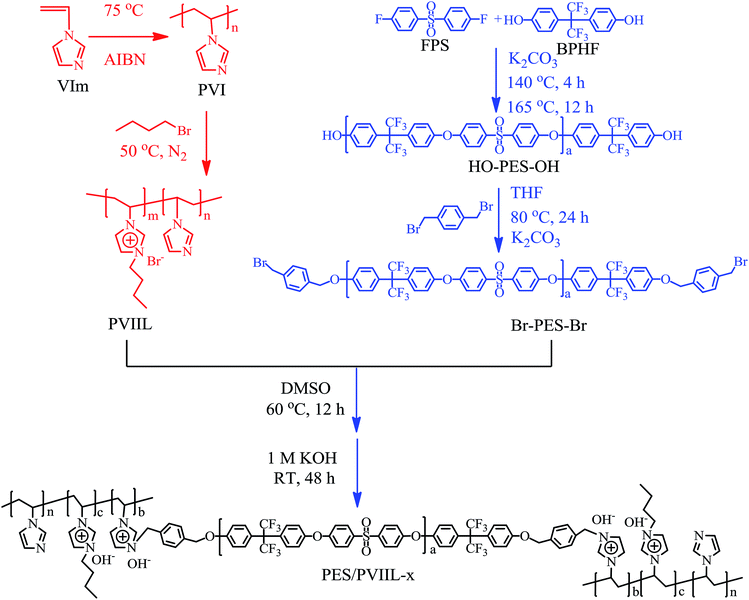
In order to further convert HO-PES-OH into Br-PES-Br, α,α′-dibromo-p-xylene and THF were employed as the end-capping reagent and solvent respectively as illustrated in Scheme 1. Typically, HO-PES-OH (0.926 g, 0.3 mmol), α,α′-dibromo-p-xylene (0.396 g, 1.5 mmol) and K2CO3 (0.417 g, 3 mmol) were simultaneously charged into THF (30 mL) contained in a 100 mL three-necked flask equipped with a condenser, a magnetic stirrer, a nitrogen inlet and outlet. The resulting mixture was heated to 80 °C to take a reaction under a nitrogen atmosphere for 24 h. The precipitation and purification were conducted at the same conditions as described above. Finally, the pure Br-PES-Br was obtained and kept in a desiccator.
After vigorously stirring for 5 min, the resulting mixture was filtered through a 0.45 μm PTFE filter, poured onto a flat glass plate and then dried at 60 °C in a vacuum oven for 24 h to slowly evaporate the solvent. The resultant transparent membrane is gently peeled off from the plate and treated with a 1 M aqueous KOH solution at RT for 24 h to produce the hydroxide form membrane. Next, the membrane was repeatedly washed with deionized (DI) water for more than 48 h and then kept in N2-saturated DI water in a sealed container in order to avoid carbon dioxide contamination. The as-obtained crosslinked membrane is designated as PES/PVIIL-x, where x is the feeding weight fraction of Br-PES-Br. Herein, three kinds of membranes (PES/PVIIL-0.67, PES/PVIIL-0.5 and PES/PVIIL-0.4) were prepared.
Morphology and composition characterization
 | (1) |
 | (2) |
 | (3) |
 | (4) |
 | (5) |
Results and discussion
Synthesis and structure of copolymers and PES/PVIIL-x membranes
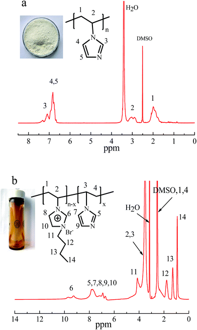
PVIIL was made from partial functionalization of PVI with 1-bromobutane. This reaction proceeded smoothly owing to the weak steric hindrance and strong nucleophilicity of the 3-position nitrogen atom in the imidazole ring as well as the high reactivity of 1-bromobutane.5 Fig. 1b shows the 1H NMR spectra of the as-synthesized PVIIL in the range of 0–11 ppm with DMSO as the deuterated reagent. Compared with PVI, peaks of protons from CH/CH2 groups on the PVIIL main chain shift to downfield, appearing at the chemical shift of 1.9–2.8 ppm and 3.2–3.9 ppm. The wide peak corresponding to protons from the PVI imidazole ring is divided into three peaks in the interval from 6.5 to 10.0 ppm when it is partially functionalized into PVIIL.41 The different chemical environments of imidazolium cations and imidazole are probably responsible for the two part peaks. The quaternization degree of PVIIL was calculated to be 68% from the integrating ratio of protons on C2-position of imidazolium cations (H6) and all imidazole rings (H5–H10) (DQ = 3H6/H5–10 = (3 × 1.00)/4.42 = 68%). Overall, all of the bands at 0.6–5.0 ppm are consistent with protons in the pendant alkyl chain,42 thus suggesting the presence of 1-bromobutane in the structure.
In order to make AEMs with sufficient IEC, HO-PES-OH with predetermined molecule weight was synthesized via polycondensation reaction using K2CO3 as the acid-binding agent. Subsequently, Br-PES-Br was prepared from the HO-PES-OH by end-capping with excess α,α′-dibromo-p-xylene. The structures of the HO-PES-OH and Br-PES-Br as recorded by 1H NMR in CDCl3 are shown in Fig. S1.†
The peaks between 6.9 and 8.1 ppm (Fig. S1a†) are ascribed to protons from the benzene ring in the PES chain.39 Meanwhile, the new peaks at 4.5 and 5.1 ppm in the 1H NMR spectra of Br-PES-Br (Fig. S1b†) are associated with the methylene protons in the CH2Br group from α,α′-dibromo-p-xylene. This suggests the successful termination of HO-PES-OH.43 Furthermore, the molecular weight of HO-PES-OH and Br-PES-Br as determined by GPC is shown in Fig. S2.† The synthesized Br-PES-Br has a higher molecular weight (Mn = 9.66 × 10³ Da and Mw = 13.43 × 10³ Da) than HO-PES-OH Mn = (7.98 × 10³ Da) and Mw = (10.98 × 10³ Da) after termination. However, the increment in Mn and Mw from HO-PES-OH to Br-PES-Br is a little higher than the theoretical values (∼350 Da) calculated from end-capping groups. This is mainly because a portion of Br-PES-Br with lower molecular weight may lose during purification leading to the production of Br-PES-Br with higher molecular weight than theoretical values. Moreover, there are unavoidable errors that result from the processing of GPC data of HO-PES-OH/Br-PES-Br within the uncertainty of the measurements (below 10%).44
The FT-IR spectra of the membranes and Br-PES-Br solid are shown in Fig. S3.† In comparison with Br-PES-Br, the as-synthesized membranes display new strong absorption peaks at 3068, 1656 and 1365 cm−1 which are attributed to the stretching vibration of C–H and C–N in the imidazole ring and C–H in 1-bromobutane, respectively.39,45 The intensity of these peaks increased with the PVIIL content, suggesting that the PVIIL was successfully introduced to the Br-PES-Br chain during the membrane formation. The broad peak around 3476 cm−1 for the membranes is assigned to the stretching vibration of –OH.
Menshutkin reaction occurred when Br-PES-Br was mixed with PVIIL at 60 °C, forming the Br−-form PES/PVIIL-x membranes. The Br−-form membranes are then immersed in a KOH solution to exchange Br− with OH−, thus producing the OH−-form PES/PVIIL-x. The EDS spectra of the Br−-form PES/PVIIL-0.4 and OH−-form PES/PVIIL-0.4 were recorded to compare their core elemental composition. It can be observed in Fig. 2 that the sharp peak of bromine in Br−-form PES/PVIIL-0.4 (Fig. 2a) declined and almost disappeared in the OH−-form PES/PVIIL-0.4 (Fig. 2b).
Furthermore, the membranes are insoluble in most of the commonly used organic solvents including dimethylformamide (DMF), dimethyl sulfoxide (DMSO), tetrahydrofuran (THF), chloroform (CHCl3) and methanol at RT. This suggests the effective crosslinking within the membranes and vindicates the grafting of the Br-PES-Br chain onto the PVIIL backbone via crosslinking. This is also supported by the gel fractions (>87%) in DMSO shown in Table 1.
| PES/PVIIL-x | DCa (%) | IEC (meq g−1) | Water uptake (%) | Swelling ratio (%) | Gel fraction (%) | |||
|---|---|---|---|---|---|---|---|---|
| Cal.a | Exp.b | 30 °C | 60 °C | 30 °C | 60 °C | |||
| a Calculated from the feeding monomer ratios.b Experimental value determined by titration. | ||||||||
| 0.67 | 12.4 | 1.53 | 0.73 | 4.12 ± 0.16 | 6.93 ± 0.17 | 4.42 ± 0.10 | 7.64 ± 0.12 | 93% |
| 0.5 | 6.2 | 2.21 | 1.34 | 16.29 ± 0.17 | 19.96 ± 0.19 | 7.14 ± 0.12 | 11.47 ± 0.11 | 91% |
| 0.4 | 4.2 | 2.59 | 1.67 | 23.54 ± 0.15 | 28.37 ± 0.20 | 9.23 ± 0.15 | 15.44 ± 0.13 | 87% |
Morphology of the PES/PVIIL-x membranes
A representative morphology of the as-synthesized membranes is shown in Fig. 3. The membrane is transparent and flexible (Fig. 3a), which is a direct indicative of their good mechanical robustness for application in fuel cells. The microstructure of the AEMs reveals that both the membrane surface (Fig. 3b) and cross-section (Fig. 3c) are dense without pores. Meanwhile, the thickness of the as-synthesized membrane was estimated to be around 40 μm (Fig. 3c). A thin (tens of micrometer) AEM tends to reduce the ohmic loss in cell voltage and thus promotes the power density of the PEMFCs.13 | ||
| Fig. 3 Images of the PES/PVIIL-0.4 membrane: (a) digital photo, SEM image of (b) surface and (c) cross-section. | ||
The surface topography of the AEMs was studied by AFM, as shown in Fig. 4. The darker regions are attributed to the soft hydrophilic domains while the brighter ones correspond to the hard hydrophobic domains.46 Distinct phase separation is seen in all of the membranes, and suggests the excellent structural design of AEMs adopted in this work as illustrated in Scheme 1.
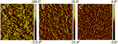 | ||
| Fig. 4 AFM phase image of (a) PES/PVIIL-0.67 (b) PES/PVIIL-0.5 and (c) PES/PVIIL-0.4 membranes. Scale: 500 × 500 nm. | ||
The hydrophobic Br-PES-Br chain is immiscible with the hydrophilic PVIIL backbone, the domains containing imidazolium cations gather together and self-assemble to form the hydrophilic ionic clusters. By increasing the ratio of PVIIL to PES (PES/PVIIL-0.4), the interconnectivity of hydroxide domains become more pronounced because the size of the hydrophilic domains increased with the amount of imidazolium cations introduced into the polymer backbone, resulting in the more prominent ionic nanochannels. These hydrophilic nanochannels are highly favourable for the conduction of hydroxide ions.
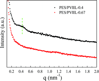
SAXS was further employed to investigate the microphase separation of the AEMs. As shown in Fig. 5, the PES/PVIIL-0.4 membrane with more dense ionic groups tends to display more profound scattering peak, which suggests larger spacing of ion conducting channels.47–49 The wide scattering peak at 0.42 nm−1 for the PES/PVIIL-0.4 membrane corresponds to the average interdomain spacing, d of 14.9 nm (Bragg equation (d = 2π/q)). In contrast, there are no observable peaks for the PES/PVIIL-0.67 membrane, probably due to the tiny interdomain spacing. This increased Bragg spacing with increased ratio of PVIIL to Br-PES-Br is consistent with the results of AFM.
Properties of the PES/PVIIL-x membranes
Moderate amount of water molecules is beneficial to facilitate the hydroxide conductivity of the membranes while excess water could result in poor mechanical properties.50 Fig. 6a shows the water uptake and contact angle of the crosslinked membranes. The water uptake of the membranes expectedly increases with increasing IEC as well as with temperature. This is because the membranes with higher IEC exhibit higher affinity to water and higher mobility of water molecules. Polymer chains at higher temperature tend to create larger free volume. Meanwhile, PES/PVIIL-x membranes displayed a lower water uptake in the range of 4.12–23.54% than the conventional imidazolium-based AEMs.5,51,52 This is because the strong hydrophobicity of poly(ether sulfone)s chain as well as the dense crosslinked structure simultaneously limits the excessive water uptake conducing to fewer water molecules absorbed in the membranes. In addition, the contact angle of the AEMs decreases from 94.39° to 67.55° with increasing the IEC. This suggests that the hydrophilicity of the AEMs increased with increasing the number of ionic groups.
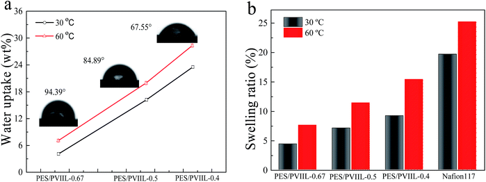 | ||
| Fig. 6 (a) Water uptake and static water contact angle of the crosslinked PES/PVIIL-x membranes, (b) SR of the crosslinked PES/PVIIL-x membranes and Nafion® 117. | ||
The swelling ratio of the PES/PVIIL-x membranes is shown in Fig. 6b. Notably, the relationship between SR and IEC/temperature agrees well with that between water uptake and IEC/temperature. This is because higher water uptake always results in larger dimensional changes in the membrane. Compared with PES/PVIIL-0.67 and PES/PVIIL-0.5, the PES/PVIIL-0.4 membrane has the highest swelling ratio of 9.23% at 30 °C and 15.44% at 60 °C. Nevertheless, this value is much lower than that for Nafion-117 under the same testing condition (Fig. 6b). This is probably due to the crosslinked network formed within the membranes that effectively restricts the mobility of polymer chains, thus resulting in high dimensional stability.
![[thin space (1/6-em)]](https://www.rsc.org/images/entities/char_2009.gif) :
:![[thin space (1/6-em)]](https://www.rsc.org/images/entities/char_2009.gif) y membranes with comparable IEC.54 Moreover, the high conductivity of the PES/PVIIL-0.4 membrane is accompanied by a lower swelling ratio than the uncrosslinked AEMs with similar conductivity.45,51 This is probably because the hydrophilic/hydrophobic microphase separation morphology formed within the membrane efficiently promotes the hydroxide transport as confirmed by AFM. The crosslinked membranes with more compact network structure were expected to display higher mechanical stability.
y membranes with comparable IEC.54 Moreover, the high conductivity of the PES/PVIIL-0.4 membrane is accompanied by a lower swelling ratio than the uncrosslinked AEMs with similar conductivity.45,51 This is probably because the hydrophilic/hydrophobic microphase separation morphology formed within the membrane efficiently promotes the hydroxide transport as confirmed by AFM. The crosslinked membranes with more compact network structure were expected to display higher mechanical stability.
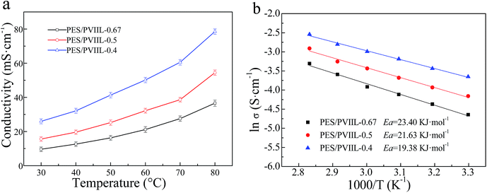 | ||
Fig. 7 (a) Temperature dependence of the ionic conductivity and (b) ln![[thin space (1/6-em)]](https://www.rsc.org/images/entities/char_2009.gif) σ–1/T plot of the crosslinked membranes (PES/PVIIL-x). σ–1/T plot of the crosslinked membranes (PES/PVIIL-x). | ||
Furthermore, the temperature dependence of conductivity is observed to be in good conformity with Arrhenius law, as shown in Fig. 7b. The estimated transport activation energy of OH− in the membranes follows the Arrhenius relation: Ea = −bR, where R is the universal gas constant (R = 8.314 J mol−1 K−1), and b is the slope of the Arrhenius plot, in the range of 19.38–23.40 kJ mol−1. The membranes with higher IEC have lower Ea. This is because more ionic groups tend to absorb more water molecules and form more developed nanochannels inside the membrane, and thus facilitating the transport of hydroxide.51
Sufficient mechanical strength is another essential property for AEMs to meet the requirement for hot-press and long-term application. Table 2 shows the mechanical properties of the as-synthesized PES/PVIIL-x membranes at RT. By increasing the IEC, the tensile strength of the membranes decreases from 32.9 to 21.2 MPa, the Young's modulus decreases from 509 to 197 MPa and the elongation at break increases from 14.5% to 33.8%. The reduced tensile strength and the improved elongation at break of the crosslinked membranes could be attributed to the abundant ionic groups that induce higher water uptake and the absorbed water acts as a plasticizer,52 thus weakening the mechanical properties.
| Membranes | Tensile strength (MPa) | Young's modulus (MPa) | Elongation at break (%) | |||
|---|---|---|---|---|---|---|
| Before | After | Before | After | Before | After | |
| PES/PVIIL-0.67 | 32.9 ± 1.2 | 25.8 ± 1.4 | 509 ± 23 | 424 ± 20 | 14.5 ± 1.3 | 9.6 ± 0.8 |
| PES/PVIIL-0.5 | 28.4 ± 1.3 | 22.6 ± 1.5 | 321 ± 18 | 288 ± 15 | 26.7 ± 1.8 | 21.3 ± 1.5 |
| PES/PVIIL-0.4 | 21.2 ± 0.9 | 17.3 ± 0.8 | 197 ± 12 | 162 ± 11 | 33.8 ± 2.1 | 29.6 ± 1.9 |
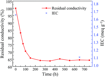 | ||
| Fig. 9 Time dependent residual conductivity and IEC of the PES/PVIIL-0.4 membrane in a 2 M KOH solution at 60 °C. | ||
Furthermore, the FT-IR spectra of the membranes after exposure to the alkaline environment for 30 days are shown in Fig. S5.† The membranes maintain a considerable stability in alkaline media considering only tiny change in the intensity of the imidazolium groups.
The changes in mechanical properties of the PES/PVIIL-0.4 membranes after 30 days' alkaline stability test (Table 2) reveal 18% loss in tensile strength for the PES/PVIIL-0.4 membrane. This is due to the destruction of crosslinked network when imidazolium groups were degraded. Nonetheless, the conductivity and mechanical property after the alkali accelerated test still maintain a moderate level, suggesting a reasonable alkaline-resistance for long-term application. Especially, the PES/PVIIL-0.4 membrane displayed higher alkaline resistance than the quaternary ammonium based AEMs.55–57 This is possibly due to the following reasons: (1) the presence of the π-conjugated imidazole ring reduced the SN2 substitution reactions thus improved the chemical stability of the imidazolium cations.3 (2) The effective crosslinked network in this study probably protects the membranes from hydroxide ions attack, which is consistent with the results on conductivity and mechanical property.
The current work especially focused on the novel synthesis method, properties of the AEMs and the single-cell performance without optimization. For a better single cell performance, the MEA fabrication method and testing condition are underway in our lab.
Conclusions
We have synthesized a series of novel macrocrosslinked imidazolium-based AEMs by crosslinking poly(vinyl imidazole)ionic liquid with bromide-terminated poly(ether sulfone) via Menshutkin reaction. The as-synthesized PES/PVIIL-x membranes demonstrated low water uptake and enhanced dimensional stability due to the formation of crosslinked network structure. The incompatibility of the hydrophilic imidazolium cations from the functionalized poly(vinyl imidazole) with the long hydrophobic poly(ether sulfone) chain promoted the hydrophilic/hydrophobic phase separation. Notably, the PES/PVIIL-0.4 membrane with the IEC of 1.67 meq g−1 displayed the highest hydroxide conductivity of 78.5 mS cm−1 at 80 °C. All of the PES/PVIIL-x membranes exhibited good thermal stability and robust mechanical properties that meet the requirements for applications in alkaline fuel cells. Moreover, the PES/PVIIL-0.4 membrane can maintain 65% conductivity and 82% tensile strength after immersing in a 2 M KOH solution at 60 °C for 30 days. The high performances of PES/PVIIL-0.4 membrane demonstrates its potentiality for fuel cell application.Acknowledgements
Financial support from the National Nature Science Foundation of China (grant no. 21376194 & 21576226), and the research fund for the Priority Areas of Development in Doctoral Program of Higher Education (no. 20130121130006) is gratefully acknowledged.Notes and references
- M. D. T. Nguyen, S. Yang and D. Kim, J. Power Sources, 2016, 328, 355–363 CrossRef CAS.
- H. Y. Yao, N. N. Song, K. X. Shi, S. N. Feng, S. Y. Zhu, Y. H. Zhang and S. W. Guan, Polym. Chem., 2016, 7, 4728–4735 RSC.
- B. C. Lin, H. L. Dong, Y. Y. Li, Z. H. Si, F. L. Gu and F. Yan, Chem. Mater., 2013, 25, 1858–1867 CrossRef CAS.
- G. Das, B. J. Parkb and H. H. Yoon, J. Mater. Chem. A, 2016, 4, 15554–15564 CAS.
- W. Li, J. Fang, M. Lv, C. X. Chen, X. J. Chi, Y. X. Yang and Y. M. Zhang, J. Mater. Chem., 2011, 21, 11340–11346 RSC.
- A. K. Sahu, K. Ketpang, S. Shanmugam, O. Kwon, S. Lee and H. Kim, J. Phys. Chem. C, 2016, 120, 15855–15866 CAS.
- Y. H. Yin, Z. Li, X. Yang, L. Cao, C. B. Wang, B. Zhang, H. Wu and Z. Y. Jiang, J. Power Sources, 2016, 332, 265–273 CrossRef CAS.
- B. C. Lin, F. Q. Chu, Y. R. Ren, B. P. Jia, N. Y. Yuan, H. Shang, T. Y. Feng, Y. Y. Zhu and J. N. Ding, J. Power Sources, 2014, 266, 186–192 CrossRef CAS.
- L. S. Wang, A. N. Lai, C. X. Lin, Q. G. Zhang, A. M. Zhu and Q. L. Liu, J. Membr. Sci., 2015, 492, 58–66 CrossRef.
- H. S. Dang and P. Jannasch, Macromolecules, 2015, 48, 5742–5751 CrossRef CAS.
- M. Zhang, J. L. Liu, Y. G. Wang, L. N. An, M. D. Guiver and N. W. Li, J. Mater. Chem. A, 2015, 3, 12284–12296 CAS.
- Z. J. Yang, J. Q. Hou, X. Y. Wang, L. Wu and T. W. Xu, Macromol. Rapid Commun., 2015, 36, 1362–1367 CrossRef CAS PubMed.
- N. W. Li, Q. Zhang, C. Y. Wang, Y. M. Lee and M. D. Guiver, Macromolecules, 2012, 45, 2411–2419 CrossRef CAS.
- H. Ono, J. Miyake, S. Shimada, M. Uchida and K. Miyatake, J. Mater. Chem. A, 2015, 3, 21779–21788 CAS.
- M. Iravaninia and S. Rowshanzamir, Fuel Cells, 2016, 16, 135–149 CrossRef CAS.
- X. M. Wu, W. T. Chen, X. M. Yan, G. H. He, J. J. Wang, Y. Zhang and X. P. Zhu, J. Mater. Chem. A, 2014, 2, 12222–12231 CAS.
- W. T. Chen, X. M. Yan, X. M. Wu, S. Q. Huang, Y. L. Luo, X. Gong and G. H. He, J. Membr. Sci., 2016, 514, 613–621 CrossRef CAS.
- Q. Li, L. Liu, Q. Q. Miao, B. K. Jin and R. Bai, Chem. Commun., 2014, 50, 2791–2793 RSC.
- E. A. Weiber and P. Jannasch, J. Membr. Sci., 2016, 520, 425–433 CrossRef CAS.
- J. R. Varcoe, P. Atanassov, D. R. Dekel, A. M. Herring, M. A. Hickner, P. A. Kohl, A. R. Kucernak, W. E. Mustain, K. Nijmeijer, K. Scott, T. W. Xu and L. Zhuang, Energy Environ. Sci., 2014, 7, 3135–3191 CAS.
- J. Pan, C. Chen, Y. Li, L. Wang, L. S. Tan, G. W. Li, X. Tang, L. Xiao, J. T. Lu and L. Zhuang, Energy Environ. Sci., 2014, 7, 354–360 CAS.
- C. H. Hsu and C. C. Wan, J. Power Sources, 2003, 115, 268–273 CrossRef CAS.
- S. Y. Lee, N. R. Kang, D. W. Shin, C. H. Lee, K. S. Lee, M. D. Guiver, N. W. Li and Y. M. Lee, Energy Environ. Sci., 2012, 5, 9795–9802 CAS.
- K. H. Lee, D. H. Cho, Y. M. Kim, S. J. Moon, J. G. Seong, D. W. Shin, J. Y. Sohn, J. F. Kima and Y. M. Lee, Energy Environ. Sci., 2017, 10, 275–285 CAS.
- G. H. Nie, X. H. Li, J. X. Tao, W. J. Wu and S. J. Liao, J. Membr. Sci., 2015, 474, 187–195 CrossRef CAS.
- J. Ran, L. Wu, Q. Q. Ge, Y. Y. Chen and T. W. Xu, J. Membr. Sci., 2014, 470, 229–236 CrossRef CAS.
- D. Guo, Y. Z. Zhuo, A. N. Lai, Q. G. Zhang, A. M. Zhu and Q. L. Liu, J. Membr. Sci., 2016, 518, 295–304 CrossRef CAS.
- A. H. N. Rao, S. Y. Namb and T. H. Kim, Int. J. Hydrogen Energy, 2014, 39, 5919–5930 CrossRef CAS.
- Y. Z. Zhuo, A. N. Lai, Q. G. Zhang, A. M. Zhu, M. L. Ye and Q. L. Liu, J. Membr. Sci., 2015, 491, 138–148 CrossRef CAS.
- S. Vengatesan, S. Santhi, G. Sozhan, S. Ravichandran, D. J. Davidson and S. Vasudevan, RSC Adv., 2015, 5, 27365–27371 RSC.
- J. J. Wang, G. H. He, X. M. Wu, X. M. Yan, Y. P. Zhang, Y. D. Wang and L. Du, J. Membr. Sci., 2014, 459, 86–95 CrossRef CAS.
- C. X. Lin, X. L. Huang, D. Guo, Q. G. Zhang, A. M. Zhu, M. L. Ye and Q. L. Liu, J. Mater. Chem. A, 2016, 4, 13938–13948 CAS.
- N. W. Li, Y. J. Leng, M. A. Hickner and C. Y. Wang, J. Am. Chem. Soc., 2013, 135, 10124–10133 CrossRef CAS PubMed.
- X. Dong, S. H. Hou, H. C. Maoa, J. F. Zheng and S. B. Zhang, J. Membr. Sci., 2016, 518, 31–39 CrossRef CAS.
- X. H. Li, Q. F. Liu, Y. F. Yu and Y. Z. Meng, J. Membr. Sci., 2014, 467, 1–12 CrossRef CAS.
- Y. B. He, J. J. Si, L. Wu, S. L. Chen, Y. Zhu, J. F. Pan, X. L. Ge, Z. J. Yang and T. W. Xu, J. Membr. Sci., 2016, 515, 189–195 CrossRef CAS.
- B. C. Lin, L. H. Qiu, J. M. Lu and F. Yan, Chem. Mater., 2010, 22, 6718–6725 CrossRef CAS.
- M. L. Guo, J. Fang, H. K. Xu, W. Li, X. H. Lu, C. H. Lan and K. Y. Li, J. Membr. Sci., 2010, 362, 97–104 CrossRef CAS.
- A. N. Lai, K. Zhou, Y. Z. Zhuo, Q. G. Zhang, A. M. Zhu, M. L. Ye and Q. L. Liu, J. Membr. Sci., 2016, 497, 99–107 CrossRef CAS.
- A. Jasti and V. K. Shahi, J. Power Sources, 2014, 267, 714–722 CrossRef CAS.
- K. Emmanuel, C. L. Cheng, B. Erigene, A. N. Mondal, M. M. Hossain, M. I. Khan, N. UlAfsar, G. Liang, L. Wu and T. W. Xu, J. Membr. Sci., 2016, 497, 209–215 CrossRef CAS.
- B. Qiu, B. C. Lin, Z. H. Si, L. H. Qiu, F. Q. Chu, J. Zhao and F. Yan, J. Power Sources, 2012, 217, 329–335 CrossRef CAS.
- P. Y. Xu, K. Zhou, G. L. Han, Q. G. Zhang, A. M. Zhu and Q. L. Liu, J. Membr. Sci., 2014, 457, 29–38 CrossRef.
- J. C. Moore and J. G. Hendrickson, J. Polym. Sci., Part C: Polym. Symp., 1965, 8, 233–241 CrossRef.
- A. N. Lai, L. S. Wang, C. X. Lin, Y. Z. Zhuo, Q. G. Zhang, A. M. Zhu and Q. L. Liu, J. Membr. Sci., 2015, 481, 9–18 CrossRef CAS.
- J. Pan, Y. Li, J. J. Han, G. W. Li, L. S. Tan, C. Chen, J. T. Lu and L. Zhuang, Energy Environ. Sci., 2013, 6, 2912–2915 CAS.
- W. Germer, J. Leppin, C. N. Kirchner, H. Cho, H. J. Kim, D. Henkensmeier, K. Y. Lee, M. Brela, A. Michalak and A. Dyck, Macromol. Mater. Eng., 2015, 300, 497–509 CrossRef CAS.
- L. Z. Wang and M. A. Hickner, Polym. Chem., 2014, 5, 2928–2935 RSC.
- L. Z. Wang and M. A. Hickner, Soft Matter, 2016, 12, 5359–5371 RSC.
- M. A. Hossain, H. Jang, S. Lee, T. Hong, L. Jin, F. Tan, D. Kim and W. Kim, Int. J. Hydrogen Energy, 2015, 40, 1324–1332 CrossRef CAS.
- C. X. Lin, Y. Z. Zhuo, A. N. Lai, Q. G. Zhang, A. M. Zhu, M. L. Ye and Q. L. Liu, J. Membr. Sci., 2016, 513, 206–216 CrossRef CAS.
- A. N. Lai, L. S. Wang, C. X. Lin, Y. Z. Zhuo, Q. G. Zhang, A. M. Zhu and Q. L. Liu, ACS Appl. Mater. Interfaces, 2015, 7, 8284–8292 CAS.
- L. Gao, G. H. He, Y. Pan, B. L. Zhao, X. W. Xu, Y. J. Liu, R. L. Deng and X. M. Yan, J. Membr. Sci., 2016, 518, 159–167 CrossRef CAS.
- S. Vengatesan, S. Santhi, G. Sozhan, S. Ravichandran, D. J. Davidson and S. Vasudevan, RSC Adv., 2015, 5, 27365–27371 RSC.
- T. Sata, M. Tsujimoto, T. Yamaguchi and K. Matsusaki, J. Membr. Sci., 1996, 112, 161–170 CrossRef CAS.
- S. Chempath, B. R. Einsla, L. R. Pratt, C. S. Macomber, J. M. Boncella, J. A. Rau and B. S. Pivovar, J. Phys. Chem. C, 2008, 112, 3179–3182 CAS.
- C. S. Macomber, J. M. Boncella, B. S. Pivovar and J. A. Rau, J. Therm. Anal. Calorim., 2008, 93, 225–229 CrossRef CAS.
- H. W. Zhang, D. Z. Chen, Y. Xianze and S. B. Yin, Fuel Cells, 2015, 15, 761–780 CrossRef CAS.
- L. Wu, Q. Pan, J. R. Varcoe, D. Zhou, J. Ran, Z. J. Yang and T. W. Xu, J. Membr. Sci., 2015, 490, 1–8 CrossRef CAS.
- Y. T. Luo, J. C. Guo, C. S. Wang and D. Chu, Electrochem. Commun., 2012, 16, 65–68 CrossRef CAS.
Footnote |
| † Electronic supplementary information (ESI) available: Preparation of the crosslinked PES/PVIIL-x membranes; 1H NMR spectra of (a) HO-PES-OH and (b) Br-PES-Br in CDCl3; GPC plots of HO-PES-OH and Br-PES-Br in the experiment; FT-IR spectra of the PES/PVIIL-x membranes and Br-PES-Br; FT-IR spectra of the PES/PVIIL-0.4 membrane (i) before (ii) after immersing in a 2 M KOH solution at 60 °C for 30 days. See DOI: 10.1039/c7ra04170e |
| This journal is © The Royal Society of Chemistry 2017 |

