 Open Access Article
Improving the extracellular electron transfer of Shewanella oneidensis MR-1 for enhanced bioelectricity production from biomass hydrolysate†
Yan-Zhai Wang‡
a,
Yu Shen‡b,
Lu Gaoa,
Zhi-Hong Liaoa,
Jian-Zhong Suna and
Yang-Chun Yong *ac
*ac
aBiofuels Institute, School of the Environment, Jiangsu University, 301 Xuefu Road, Zhenjiang 212013, Jiangsu Province, China. E-mail: ycyong@ujs.edu.cn; Fax: +86-511-8879 0955; Tel: +86-511-8878 6708
bCollege of Environment and Resources, Chongqing Technology and Business University, Chongqing Institute of Green and Intelligent Technology, Chinese Academy of Sciences, Chongqing 401122, China
cJiangsu Key Laboratory of Chemical Pollution Control and Resources Reuse, Nanjing University of Science and Technology, Nanjing 210094, P. R. China
First published on 13th June 2017
Abstract
Direct electricity production from biomass hydrolysate by microbial fuel cells (MFC) holds great promise for the development of the sustainable biomass industry. Shewanella oneidensis MR-1 is one of the most extensively studied model exoelectrogens in MFC. But it is still unclear whether this model strain could generate bioelectricity from biomass or not. Here, a biomass hydrolysate MFC was constructed by using S. oneidensis MR-1 and electricity output was obtained from corn straw hydrolysate. More impressively, by promoting the extracellular electron transfer efficiency with electron shuttle addition and electrode modification using the vertically aligned polyaniline (PANI) nanowire array, the electricity output from biomass hydrolystate by S. oneidensis MR-1 was greatly improved and a high energy output was obtained, i.e., ∼1260 mA m−2 current output (∼7-fold increase over that of the control) and ∼660 mW m−2 power output (∼37-fold increase over that of the control) were achieved. This work demonstrates that S. oneidensis MR-1 has great potential in electrical energy harvesting from biomass hydrolysate, which broadens the fuel spectrum of the model exoelectrogen (S. oneidensis MR-1) inoculated MFC and also provides a new opportunity for the biomass industry.
Introduction
Microbial fuel cells (MFC) have attracted much attention as they can produce green energy from various waste organics.1–4 Fueling MFC with renewable resources is now considered as one of the promising strategies to develop sustainable energy systems on earth.5–8 Biomass is the most abundant renewable bioresource for sustainable bioenergy production.9 For example, about 7 × 10⁸ tonnes of agricultural biomass could be produced annually in China.10 However, biomass composed of cellulose, hemicellulose and lignin are resistant to degradation by microorganisms and hard to use as fuel for MFC. In order to achieve high bioconversion efficiency, biomass was pretreated and then hydrolyzed with acidic and/or enzymatic hydrolysis to biomass hydrolysate, which can be directly used for production of biofuels by microorganisms.11 Thus, it is possible to fuel MFC with biomass hydrolysate to directly generate electric energy from biomass, which might be developed as a complementary technology to the current biomass industry. Moreover, with the fast development of the biofuel industry, treatment of the wastewater containing the biomass hydrolysate would be another concern. MFC might be used to harness the electricity from the hydrolysate waste for valorization of this biomass industry and treat the wastewater to reduce its environmental impact.12Recently, MFCs fueled with wheat/rice straw hydrolysate were established with the mixed microbial community.5,12 By using hydrothermal treated wheat straw hydralysate as the substrate, ∼148 mW m−2 power output was obtained by using a two chamber MFC inoculated with mixed microbial community.12 Another biomass hydrolysate with about 1 time higher power output (293 mW m−2) was also developed by using acidic treated rice straw hydrolysate and anaerobic sludge as the substrate and inoculum, respectively.5 However, the mixed culture encountered drawbacks such as difficult to be reproduced (esp. at different places or operation conditions), susceptible to environmental fluctuation, complicated interspecies interaction, unknown mechanisms, and difficulty to control. More importantly, pure culture study is vital to explore the detailed biological mechanisms that may provide new insight to the MFC process and thus develop new strategies for MFC manipulation.13 Therefore, different pure cultures with the electroactivity referred as exoelectrogens had been isolated and were extensively used as MFC inoculum.14–16 However, no pure culture has been applied to biomass hydrolysate fueled MFC.
Shewanella oneidensis MR-1 is one of the most extensively studied exoelectrogens for MFC.1 It was also used as the model strain for investigation on extracellular electron transfer (EET) mechanism between cells and the electrode/metals.1 However, only few simple organic substrates have been used as fuels for S. oneidensis MR-1 inoculated MFC. The feasibility to produce electricity from mixed/complicated substrate by this model exoelectrogen is still unclear. Straw hydrolysate is a typical complicated substrate that usually contains mix sugars (e.g., glucose, xylose) and growth inhibitors (e.g., acetate). Only few bacterial species can efficiently utilize this substrate.17,18 Thus, to expand the fuel spectrum of the Shewanella MFC and explore the EET mechanism of the biomass hydrolysate MFC, it is deserved to develop a Shewanella-inoculated biomass hydrolysate fueled MFC.
In this work, we developed a pure culture biomass hydrolysate MFC and demonstrated that electricity could be generated from corn straw hydrolysate by S. oneidensis MR-1. Moreover, the power output of MFC was remarkably improved by riboflavin addition, polyaniline nanowire array electrode modification, or combination of riboflavin addition and polyaniline electrode modification, respectively. This finding implied that S. oneidensis MR-1 would be a promising inoculum for directly harvesting bioelectricity from biomass hydrolysate.
Materials and methods
Straw hydrolysate preparation
Naturally dried corn straw collected from Chongqing, China was washed with distilled water, and dried at 50 °C in an oven for 24 hours. Then, it was milled to ∼20-mesh particles, pretreated with diluted sulfuric acid method,19 and saccharified by using a commercial cellulose enzyme (Youtellbio Co., China).20 The pH of the prepared straw hydrolysate was then adjusted to ∼7.0 and stored at 4 °C for later use (the main ingredients of this corn straw hydrolysate are 21 g L−1 glucose, 11 g L−1 xylose and 1.2 g L−1 acetate). The straw hydrolysate was diluted 5 times with the MFC electrolyte (95% M9 medium with 5% LB medium, pH 7.0) and used for MFC experiment.Bacteria culture
Shewanella oneidensis MR-1 (WT) and related mutant strains (ΔMtrC, ΔOmcA, ΔMtrC/ΔOmcA21) were grown with shaking in LB broth (peptone 10 g L−1, yeast extract 5 g L−1, NaCl 10 g L−1) at 30 °C for 16 hours. The cell pellets were harvested by centrifugation and washed with M9 medium.14,15 Then, the cell pellets were resuspended in 150 mL electrolyte to an optical density (OD600) of ∼2.5 and used as MFC inoculum.22MFC set-up and electrochemical analysis
A dual chamber MFC separated with proton exchange membrane (Nafion 117) was used in this work.23 Carbon cloth (2 cm × 4 cm or 1 cm × 2 cm) was used as the anode and cathode electrode. The cell suspension in electrolyte was added into the anodic chamber, while the cathodic chamber was filled with 50 mM K3[Fe(CN)6] and KCl solution.24 The MFCs were operated at 30 °C and pH 7.0 (maintained by the phosphate buffer in the electrolyte)23 (Fig. S1†). The voltage (V) across the external resistor (R) was monitored by digital multimeter. Current density (I) was calculated as I = V/R/A, where A is the projected area of the electrode. Power density (P) was calculated as P = I × V. Polarization curve was determined by varying the external resistor at the steady state of the MFC.25 All other electrochemical analyses were performed using CHI electrochemical workstation (CHI660E, Cheng Hua Instrument Co. Ltd., Shanghai) with a saturated calomel reference electrode (SCE) and a platinum wire counter electrode. Each experiment was performed with three replicates, and was independently repeated at least two times.Polyaniline modification
For polyaniline nanowire array growth on the carbon cloth electrode, 0.1 mmol aniline was added into 9 mL HClO4 solution (1 M) and cooled in ice-bath for 5 min.26 Next, 1 mL ice-cooled ammonium persulfate (66 mM) was slowly mixed with the aniline solution. Then, the carbon cloth was immersed into the mixture and incubated at 4 °C for 24 hours. Finally, the polyaniline modified electrodes were rinsed with distilled water to remove the free polyaniline and dried at room temperature.Glucose and xylose analysis
Glucose and xylose was analyzed by high performance liquid chromatography (HPLC) as describe elsewhere.13 In brief, the samples were firstly filtrated with 0.22 mm filter to remove the cells and other particles, and then subjected to HPLC analysis with a HPLC system (Shimadzu, Japan) equipped with a equipped with a HPX-87H column (Bio-Rad, USA) and a refractive index detector. The mobile phase used is 7 mM H2SO4 at a flow rate of 0.2 mL min−1. Total reducing sugars were determined by 3,5-dinitryl-salicylic acid reagent (DNS) method as described elsewhere.27Results and discussion
Performance of Shewanella MFC fueled with corn straw hydrolysate
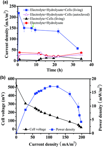
In order to determine the possibility to produce electricity from straw hydrolysate by pure culture, the model exoelectrogen S. oneidensis MR-1 was inoculated into the MFC fueled with corn straw hydrolysate. The current output from MFC inoculated with S. oneidensis MR-1 and fueled with straw hydrolysate (denoted as straw hydrolysate MFC) was monitored during discharge in constant-load mode with an external resistor of 2 kΩ. As shown in Fig. 1a, a steady current output of ∼150 mA m−2 that maintained for over 20 hours was achieved. Moreover, the consumption of glucose (85%) and xylose (65%) was also observed after 35 hours operation. To exclude possible contribution of electricity produced by pure electrochemical reaction or other possible electron donor (very low concentration of LB medium used in the electrolyte), the current outputs of the abiotic control MFC (electrolyte with straw hydrolysate but without bacteria) and the biotic control MFC (electrolyte with bacteria but without straw hydrolysate) were determined (Fig. 1a). When the straw hydrolysate was added into the electrolyte (abiotic control), a low baseline current of about 20–40 mA m−2 was observed, which might ascribed to the weak electrochemical reaction occurred in the straw hydrolysate under the MFC condition. Meanwhile, only about 10–20 mA m−2 baseline current delivered for the biotic control MFC. To further verify the function of S. oneidensis MR-1, MFC inoculated with dead cells (autolaved) was also performed. It was found that the MFC with dead cells did not show significant electricity output compared with the abiotic control (electrolyte + hydrolysate), indicating the bioactivity of S. oneidensis MR-1 cells was responsible for the electricity generation in this hydrolysate MFC. Taking together, the results indicated that electricity delivered from the straw hydrolysate MFC was mainly based on the bioelectrocatalysis of straw hydrolysate by S. oneidensis MR-1, which substantiated that the corn straw hydrolysate could be used as fuel for S. oneidensis MR-1 inoculated MFC.To estimate the maximum power output of the straw hydrolysate MFC, the polarization curve and power output curve were determined by varying the external resistors.28 As shown in Fig. 1b, the maximum power density delivered by this MFC was 17.2 ± 0.3 mW m−2. It is proved that the power outputs generated from different industrial wastewater were varied and some kinds of wastewater such as chemical industry wastewater might be unsuitable for MFC.29 The power output (17.2 ± 0.3 mW m−2) obtained here by using pure culture was also comparable with that from MFC with dark fermentation effluent (1–19 mW m−2) using the mixed cultures.30 The result indicated that biomass hydrolysate wastewater could be suitable substrate for electricity generation and treatment in MFCS. As glucose and xylose are the main organic electron donors for bacteria in the straw hydrolysate, the MFC power output fueled with pure glucose or xylose was determined to estimate the performance potential of the straw hydrolysate MFC. Impressively, a much higher power output (∼32–35 mW m−2) and nearly completed substrate consumption (over 95%) were obtained. The results implied that possible inhibitors presented in the corn straw hydrolysate (such as acetate, furan derivatives)17 might suppress the electricity generation from S. oneidensis MR-1.
Extracellular electron transfer (EET) mechanism for straw hydrolysate MFC
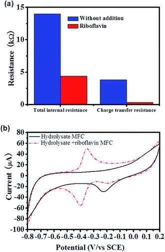
To further understand the straw hydrolysate MFC, the EET mechanisms were analyzed by using different methods. Charge transfer resistance, which directly related with the EET efficiency was estimated from the polarization curve.31 According to the polarization curve of the straw hydrolysate MFC, three typical linear parts with different slopes (V vs. I curve) could be identified, i.e., 0–25 mA cm−2, ∼25–189 mA cm−2, and ∼189–200 mA cm−2 (Fig. 1b). The first two linear parts could be used to estimate the total internal resistance and charge transfer resistance of MFC, respectively.31 Thus, the total internal resistance and the charge transfer resistance of the straw hydrolysate MFC estimated were about 14 kΩ and 4.3 kΩ, respectively (Fig. 2a). High charge transfer resistance suggested low EET efficiency between cells and the electrode.Cyclic voltammetry (CV) is a powerful tool to identify the redox reactions involved in the EET of MFC.28 The CV peak shown is the terminal element responsible for electron exchange on the surface of the electrode. As shown in Fig. 2b, the CV profile of the straw hydrolysate MFC only showed a cathodic peak centered at ∼−0.2 V (Fig. 2b), which did not present in the CV of the straw hydrolysate without bacteria inoculum (data not shown). Thus, this electrochemical activity should be assigned to the cells or cells related molecules. Moreover, it implied that this electroactive component might involve in the electron transfer of the straw hydrolysate MFC. As the cathodic peak centered at ∼−0.2 V, the mid-point potential of the corresponding redox component should be a little higher than ∼−0.2 V. It was in agreement with the observation that the anodic potential was about −162 mV, which was estimated from the open circuit voltage (OCV) of the straw hydrolysate MFC (the OCV measured was about 522 mV, while the cathodic potential was about 360 mV, thus the anodic potential was about −162 mV). The results suggested that the electroactive component identified by CV (Fig. 2b) was involved in the EET of the straw hydrolysate MFC. Flavins mediated indirect electron transfer and MtrC/OmcA involved direct electron transfer were previously identified as two of the most efficient EET pathways in S. oneidensis MR-1.32,33 However, no redox peak corresponding to flavins or MtrC/OmcA was observed in the straw hydrolysate MFC (Fig. 2b). Moreover, no detectable flavin production in the straw hydrolysate MFC was observed during HPLC analysis. The results suggested that flavin or MtrC/OmcA pathway was not actively involved in the EET of the straw hydrolysate MFC, while another inefficient EET pathway was employed which might be the cause of the high charge transfer resistance.
Genetic mutation is a direct method to test whether the corresponding genes/proteins are involved in specific bioprocess or not. To determine the role of MtrC/OmcA EET pathway in the straw hydrolysate MFC, the performance of different MtrC/OmcA mutants (i.e., single mutant strain ΔMtrC or ΔOmcA, double mutant strain ΔMtrC/ΔOmcA) was compared. Not surprisingly, all of the mutant strains showed the similar current output profile with the wild type strain (Fig. 3). The result confirmed that MtrC/OmcA EET pathway was not involved in the EET of the straw hydrolysate MFC.
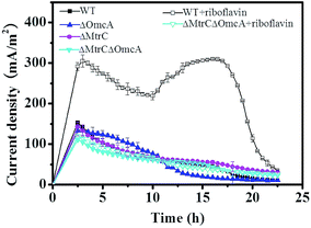 | ||
| Fig. 3 Time course of the current output of the straw hydrolysate MFCs inoculated with different strains or under different treatments. | ||
Promoted MtrC/OmcA involved EET with riboflavin addition
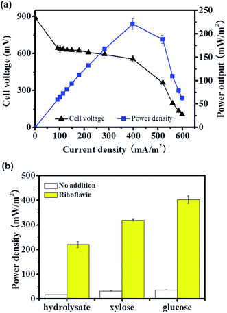
Evidences showed that the flavin mediated indirect EET or MtrC/OmcA mediated direct EET pathway was not actively involved in EET of the straw hydrolysate MFC, there are two possible explanations, i.e., the related EET components were expressed but was inactive due to no flavin or weak cell–electrode interaction, or the EET components were not expressed due to inhibition from hydrolysate. Thus, it was worth to further analyze the EET mechanism and test whether these efficient EET pathways could be activated or not.It is reasonable to speculate that the low activity of flavin mediated EET was due to low flavin production in the MFC.34 Thus, riboflavin (one of the electron shuttle used by S. oneidensis MR-1) was added into the straw hydrolysate MFC to test whether the electron shuttle mediated EET pathway could be activated or not. By addition of riboflavin, the maximum power density reached is about 12 times higher than that without riboflavin addition (221 ± 11 mW m−2 vs. 17.2 ± 0.3 mW m−2) (Fig. 4). Moreover, similar enhancement could be achieved in MFCs fueled with pure glucose or xylose (Fig. 4b). Meanwhile, the charge transfer resistance of hydrolysate MFC estimated from the polarization curve (V–I curve in Fig. 4a) was reduced about 11 times upon riboflavin addition (358 Ω vs. 4377 Ω) (Fig. 2a), which suggested dramatic improvement on EET efficiency. The results indicated that the components of riboflavin mediated EET were expressed and could be activated by riboflavin addition in the straw hydrolysate MFC.
CV analysis of the straw hydrolysate MFC supplemented with riboflavin showed a clear peak-pair centered at −0.375 V and a weak cathodic peak at about −0.2 V (Fig. 2b). The peak-pair might assign to the redox waves from riboflavin. However, the mid-point potential of riboflavin is about −0.5 V at the standard electrochemical condition.35 Similar mid-point potential shift for riboflavin was also observed in other reports,35,36 which ascribed to the interaction with the MtrC/OmcA proteins. The potential shift also facilitated the electron acceptation from the outer membrane proteins of S. oneidensis MR-1.35 Thus, the potential shift of riboflavin observed here suggested an interaction between riboflavin and MtrC/OmcA existed in this straw hydrolysate MFC, and also implied the involvement of MtrC/OmcA in the riboflavin mediated EET. Next, the role of the MtrC/OmcA was confirmed by genetic mutation, i.e., without MtrC/OmcA module (mutant strain of ΔMtrC/ΔOmcA), riboflavin addition did not enhance the current output of the straw hydrolysate MFC (Fig. 3). These results indicated that MtrC/OmcA were involved in the riboflavin mediated EET in the straw hydrolysate MFC supplemented with riboflavin, while no significant riboflavin production under the straw hydrolysate condition might be the reason for low EET efficiency and low power output. Furthermore, it also suggested that MtrC/OmcA were still functional and implied the MtrC/OmcA mediated direct EET could be activated in the straw hydrolysate MFC.
Promoted EET by electrode modification with vertically aligned polyaniline nanowire array
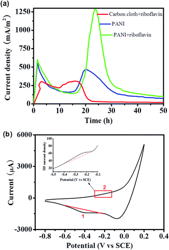
Although the EET and MFC performance could be improved with exogenously addition of riboflavin, it would be cost ineffective and might raise environmental concerns. Thus, another strategy besides riboflavin addition was developed. As evidence showed that the MtrC/OmcA proteins are functional under the straw hydrolysate condition (Fig. 3), we speculated to activate the MtrC/OmcA mediated direct EET pathway (it was proved to be an efficient outer-membrane proteins mediated EET pathway for S. oneidensis MR-1 (ref. 1,15 and 16)) in this straw hydrolysate MFC.Polyaniline (PANI) is a promising conductive polymer which had tremendous applications in electrochemical field,26,37 and is widely used as electrode modifier.23,38–40 It is proved that matchable nanoscale topography from nanostructured material would dramatically enhance the outer-membrane proteins mediated EET between cells and the electrode.15,23,41–43 Thus, the nanostructured PANI nanowire was grown and vertically aligned on the carbon cloth electrode (see ESI Fig. S2†). Interestingly, straw hydrolysate MFC equipped with the PANI modified electrode (without riboflavin addition) delivered a highest current density of about 460 mA m−2, which is about 1.5 time of that delivered from the MFC supplemented with riboflavin but equipped with unmodified electrode (Fig. 5a). More impressively, CV analysis of the anode after MFC discharge showed a cathodic peak 1 at ca. −0.41 V and a rather weak and broad anodic peak 2 at ca. −0.21 V (Fig. 5b). The peak 2 can be more clearly observed in the first derivative plot (inset of Fig. 5b), as derivative plot is a commonly used approach to differentiate the redox peaks in the complex CV profile.23,44 In S. oneidensis MR-1, the cytochrome proteins (MtrC/OmcA) usually showed an asymmetric redox pair, where the cathodic peak was much more prominent than the anodic peak.45 This voltammetric fingerprint of MtrC/OmcA could be identified in the redox pair (peak 1 and 2) observed from the straw hydrolysate MFC (Fig. 5b). Moreover, the mid-point potential of this redox pair was estimated to be −0.31 V (vs. SCE), which is in good agreement with that of the MtrC/OmcA proteins.23 Taking together, it could be concluded that the PANI modified electrode is able to improve the EET and MFC performance by enhancing the electron transfer through MtrC/OmcA mediated direct EET pathway.
Moreover, the performance potential of the hydrolysate MFC was further estimated by combination of the electrode modification and riboflavin addition. Impressively, a relatively high current density (∼1260 mA m−2), corresponding to the power density of ∼660 mW m−2, could be achieved once riboflavin was added into the straw hydrolysate MFC equipped with PANI nanowire array modified electrode. As the hydrolysate composition would be varied due to different pretreatment methods applied, the pretreatment methods should be taken into consideration for the comparison of the MFC performance. Compared with other reports using the hydrolysate with the similar pretreatment approach to the current study, the maximum power output obtained here was much higher than that obtained with wheat straw hydrolysate (123 or 148 mW m−2),6,12 rapeseed straw hydrolysate (54 mW m−2),46 and rice straw hydrolysate (293 mW m−2).4 More impressively, all these hydrolysate MFCs used mixed culture as the inoculum, while the pure culture of S. oneidensis MR-1 used in this study, which showed unique advantage of free of culture acclimation/adaptation (Fig. 1 and 5). The results indicated S. oneidensis MR-1 is promising for energy harvesting from biomass hydrolysate which would contribute to the bioenergy production and waste treatment of the biomass industry.
Conclusions
In summary, a corn straw hydrolysate MFC inoculated with pure culture of S. oneidensis MR-1 was demonstrated. The MFC without any modification delivered relatively low power output due to inefficient EET. With the EET mechanism directed optimization, the electricity generated was dramatically increased by riboflavin addition, PANI electrode modification, and the combination of riboflavin and PANI treatment, respectively. The finding of this work substantiated that S. oneidensis MR-1 could use biomass hydrolysate as fuel for electricity generation, which provided valuable model exoelectrogen system for mechanistic study of biomass MFC.Acknowledgements
The authors sincerely acknowledge the financial supports from Natural Science Foundation of Jiangsu Province (BK20160015, BK20130499), National Natural Science Foundation of China (NSFC 51578266, 21306069), Specialized Research Fund for the Doctoral Program of Higher Education (Ministry of Education, 20133227120014), Project supported by Fundamental Research Funds for the Central Universities (Grant No. 30916014102), and a project funded by the Priority Program Development of Jiangsu Higher Education Institutions.References
- B. E. Logan, Nat. Rev. Microbiol., 2009, 7, 375–381 CrossRef CAS PubMed.
- B. E. Logan and K. Rabaey, Science, 2012, 337, 686–690 CrossRef CAS PubMed.
- W. W. Li, H. Q. Yu and Z. He, Energy Environ. Sci., 2014, 7, 911–924 CAS.
- H. Y. Cheng, B. Liang, Y. Mu, M. H. Cui, K. Li, W. M. Wu and A. J. Wang, Water Res., 2015, 81, 72–83 CrossRef CAS PubMed.
- Z. Wang, T. Lee, B. Lim, C. Choi and J. Park, Biotechnol. Biofuels, 2014, 7, 9 CrossRef PubMed.
- Y. F. Zhang, B. K. Min, L. P. Huang and I. Angelidaki, Appl. Environ. Microbiol., 2009, 75, 3389–3395 CrossRef CAS PubMed.
- D. Pant, G. Van Bogaert, L. Diels and K. Vanbroekhoven, Bioresour. Technol., 2010, 101, 1533–1543 CrossRef CAS PubMed.
- P. Pandey, V. N. Shinde, R. L. Deopurkar, S. P. Kale, S. A. Patil and D. Pant, Appl. Energy, 2016, 168, 706–723 CrossRef CAS.
- P. McKendry, Bioresour. Technol., 2002, 83, 37–46 CrossRef CAS PubMed.
- X. P. Zhou, F. Wang, H. W. Hu, L. Yang, P. H. Guo and B. Xiao, Biomass Bioenergy, 2011, 35, 1–11 CrossRef.
- H. Wu, J. Lee, M. Karanjikar and K. Y. San, Bioresour. Technol., 2014, 169, 119–125 CrossRef CAS PubMed.
- A. Thygesen, F. W. Poulsen, I. Angelidaki, B. Min and A. B. Bjerre, Biomass Bioenergy, 2011, 35, 4732–4739 CrossRef CAS.
- Y. C. Yong, Y. Y. Yu, Y. Yang, C. M. Li, R. R. Jiang, X. Wang, J. Y. Wang and H. Song, Electrochem. Commun., 2012, 19, 13–16 CrossRef CAS.
- Y. C. Yong, Y. Y. Yu, C. M. Li, J. J. Zhong and H. Song, Biosens. Bioelectron., 2011, 30, 87–92 CrossRef CAS PubMed.
- Y. C. Yong, Y. Y. Yu, X. H. Zhang and H. Song, Angew. Chem., Int. Ed., 2014, 53, 4480–4483 CrossRef CAS PubMed.
- D. R. Lovley, Nat. Rev. Microbiol., 2006, 4, 497–508 CrossRef CAS PubMed.
- T. Y. Mills, N. R. Sandoval and R. T. Gill, Biotechnol. Biofuels, 2009, 2, 26 CrossRef PubMed.
- V. Novy, S. Krahulec, M. Wegleiter, G. Muller, K. Longus, M. Klimacek and B. Nidetzky, Biotechnol. Biofuels, 2014, 7, 49 CrossRef PubMed.
- K. Sasaki, D. Sasaki, Y. Sakihama, H. Teramura, R. Yamada, T. Hasunuma, C. Ogino and A. Kondo, Bioresour. Technol., 2013, 147, 84–88 CrossRef CAS PubMed.
- A. K. Chandel, F. A. F. Antunes, V. Anjos, M. J. V. Bell, L. N. Rodrigues, I. Polikarpov, E. R. de Azevedo, O. D. Bernardinelli, C. A. Rosa, F. C. Pagnocca and S. S. da Silva, Biotechnol. Biofuels, 2014, 7, 63 CrossRef PubMed.
- D. M. Cao, X. Xiao, Y. M. Wu, X. B. Ma, M. N. Wang, Y. Y. Wu and D. L. Du, Bioresour. Technol., 2013, 136, 176–181 CrossRef CAS PubMed.
- Z. H. Liao, J. Z. Sun, D. Z. Sun, R. W. Si and Y. C. Yong, Bioresour. Technol., 2015, 192, 831–834 CrossRef CAS PubMed.
- Y. C. Yong, X. C. Dong, M. B. Chan-Park, H. Song and P. Chen, ACS Nano, 2012, 6, 2394–2400 CrossRef CAS PubMed.
- D.-D. Zhai, B. Li, J.-Z. Sun, D.-Z. Sun, R.-W. Si and Y.-C. Yong, Water Sci. Technol., 2016, 73, 2176–2181 CrossRef CAS PubMed.
- B. E. Logan, B. Hamelers, R. A. Rozendal, U. Schrorder, J. Keller, S. Freguia, P. Aelterman, W. Verstraete and K. Rabaey, Environ. Sci. Technol., 2006, 40, 5181–5192 CrossRef CAS PubMed.
- N. R. Chiou, C. M. Lui, J. J. Guan, L. J. Lee and A. J. Epstein, Nat. Nanotechnol., 2007, 2, 354–357 CrossRef CAS PubMed.
- Q. Zhang, Y. Li and L. Xia, Biotechnol. Biofuels, 2014, 7, 152 CrossRef PubMed.
- Y. Qiao, S. J. Bao, C. M. Li, X. Q. Cui, Z. S. Lu and J. Guo, ACS Nano, 2008, 2, 113–119 CrossRef CAS PubMed.
- D. Pant, G. Van Bogaert, Y. Alvarez-Gallego, L. Diels and K. Vanbroekhoven, Environ. Eng. Manage. J., 2016, 15, 1897–1904 Search PubMed.
- S. B. Pasupuleti, S. Srikanth, S. V. Mohan and D. Pant, Int. J. Hydrogen Energy, 2015, 40, 12424–12435 CrossRef CAS.
- Y. Y. Yu, H. L. Chen, Y. C. Yong, D. H. Kim and H. Song, Chem. Commun., 2011, 47, 12825–12827 RSC.
- E. Marsili, D. B. Baron, I. D. Shikhare, D. Coursolle, J. A. Gralnick and D. R. Bond, Proc. Natl. Acad. Sci. U. S. A., 2008, 105, 3968–3973 CrossRef CAS PubMed.
- R. Nakamura, K. Ishii and K. Hashimoto, Angew. Chem., Int. Ed., 2009, 48, 1606–1608 CrossRef CAS PubMed.
- Y. Yang, Y. Z. Ding, Y. D. Hu, B. Cao, S. A. Rice, S. Kjelleberg and H. Song, ACS Synth. Biol., 2015, 4, 815–823 CrossRef CAS PubMed.
- A. Okamoto, S. Kalathil, X. Deng, K. Hashimoto, R. Nakamura and K. H. Nealson, Sci. Rep., 2014, 4, 5628 CrossRef CAS PubMed.
- A. Okamoto, K. Hashimoto and K. H. Nealson, Angew. Chem., Int. Ed., 2014, 53, 10988–10991 CrossRef CAS PubMed.
- L. Wang, Y. J. Ye, X. P. Lu, Z. B. Wen, Z. Li, H. Q. Hou and Y. H. Song, Sci. Rep., 2013, 3, 3568 CrossRef PubMed.
- Y. Yuan, S. G. Zhou, Y. Liu and J. H. Tang, Environ. Sci. Technol., 2013, 47, 14525–14532 CrossRef CAS PubMed.
- B. Lai, X. H. Tang, H. R. Li, Z. W. Du, X. W. Liu and Q. Zhang, Biosens. Bioelectron., 2011, 28, 373–377 CrossRef CAS PubMed.
- D.-Z. Sun, Y.-Y. Yu, R.-R. Xie, C.-L. Zhang, Y. Yang, D.-D. Zhai, G. Yang, L. Liu and Y.-C. Yong, Biosens. Bioelectron., 2017, 87, 195–202 CrossRef CAS PubMed.
- C. M. Ding, H. Liu, M. L. Lv, T. Y. Zhao, Y. Zhu and L. Jiang, Nanoscale, 2014, 6, 7866–7871 RSC.
- Y. Y. Yu, D. D. Zhai, R. W. Si, J. Z. Sun, X. Liu and Y. C. Yong, Int. J. Mol. Sci., 2017, 18, 90 CrossRef PubMed.
- S. Kalathil and D. Pant, RSC Adv., 2016, 6, 30582–30597 RSC.
- M. Palys, T. Korba, M. Bos and W. E. Vanderlinden, Talanta, 1991, 38, 723–733 CrossRef CAS PubMed.
- L. Peng, S. J. You and J. Y. Wang, Biosens. Bioelectron., 2010, 25, 2530–2533 CrossRef CAS PubMed.
- M. A. Jablonska, M. K. Rybarczyk and M. Lieder, Bioresour. Technol., 2016, 208, 117–122 CrossRef CAS PubMed.
Footnotes |
| † Electronic supplementary information (ESI) available. See DOI: 10.1039/c7ra04106c |
| ‡ Equal contribution. |
| This journal is © The Royal Society of Chemistry 2017 |

