 Open Access Article
Creative Commons Attribution 3.0 Unported Licence
Role of compensating Li/Fe incorporation in Cu0.945Fe0.055−xLixO: structural, vibrational and magnetic properties
Mohd. Nasira,
N. Patrab,
Md. A. Ahmedc,
D. K. Shuklad,
Sunil Kumare,
D. Bhattacharyab,
C. L. Prajapatf,
D. M. Phased,
S. N. Jhab,
Sajal Biring*g and
Somaditya Sen *a
*a
aDepartment of Physics, Indian Institute of Technology Indore, Indore, 453552, India. E-mail: sens@iiti.ac.in
bAtomic & Molecular Physics Division, Bhabha Atomic Research Centre, Mumbai, 400085, India
cDepartment of Physics, University of Calcutta, Kolkata, 700009, India
dUGC-DAE, Consortium for Scientific Research, Indore, 452017, India
eMetallurgical Engineering and Material Science, Indian Institute of Technology Indore, 453552, India
fTechnical Physics Division, Bhabha Atomic Research Centre, Mumbai, 400085, India
gElectronic Engg., Ming Chi University of Technology, New Taipei City, 8802, Taiwan
First published on 22nd June 2017
Abstract
Doped transition metal oxides, like CuO, are spintronic materials. An increase of magnetic moment has been reported in Fe-doped CuO.1 Additional secondary doping elements such as Li may further modify magnetism in transition metal oxides2,3 due to changes in valence state and size. Such complex doping may generate secondary impurity phases, restricting the success of such applications. Enhancement of magnetic properties strengthens applicability of the materials in devices. Single phase monoclinic Cu0.945Fe0.055−xLixO crystalline powders without any impurity are synthesized. Structural studies, electronic valence state, fine structure, and local geometry of constituent elements confirm the purity of the materials and provide clues to probable reasons leading to enhanced magnetism. Ferromagnetic coupling between neighboring spins is most likely dependent on the spin and separation between the spin species.
1. Introduction
Following the theoretical predictions of Dietl et al.,4 several efforts have been made to synthesise nanostructured dilute magnetic semiconductor oxides such as CuO, TiO2, In2O3, ZnO, SnO2, Fe2O3 etc. by doping with 3d transition metals because of their novel optical, magnetic and electric properties.5 Copper oxide has several exotic properties and potential applications in areas like spintronic devices,6 optoelectronics,7 photocatalysis,8 gas sensing,9 solar energy conversion,10 catalysis,11 electrode materials in Li-ion batteries12 and supercapacitors.13 As a building block of high temperature superconductors, a superexchange mechanism between Cu2+ ions coordinated with O in CuO (tenorite) has been widely discussed. CuO is an antiferromagnet in its ground state above the three-dimensional phase transition temperature at TN1 = 229 K and TN2 = 213 K.14 Monoclinic CuO (space group C2/c) has unique properties among all 3d monoxides since it has a square planar coordination of copper–oxygen, rather than the cubic salt structure.14 It consists of irregular Cu–O chains along the [10−1] and [101] directions.CuO nanostructures have been synthesized by hydrothermal process, spray pyrolysis, etc.15 The above techniques usually require longer reaction time and a larger amount of energy. Sol–gel technique involves less processing time but produces good yield. It has better control on stoichiometry, purity and homogeneity. Doping makes profound changes in optical, magnetic and magneto-transport properties of CuO by modifying its electronic structure. Electrical, optical, excitonic, spectroscopic and neutron diffraction studies on pristine and doped CuO with Mn, Ni, Zn, Cd, and Ti16–18 have been studied. A few reports are also available on ‘Fe’ doped CuO.1,19,20 However, only limited reports exist on codoped CuO.21,22 Ferromagnetic properties are less understood in CuO and depend on synthesis method, annealing and processing conditions. As a result different researchers arrived at diverse results for CuO nanoparticles. The changes were attributed to presence of various defects such as cation or anion vacancies, quantum size effects and uncompensated spins.23,24 Defects are generated due to the differences in atomic size, valence state and the crystal radius. The difference of crystal radius generates lattice strain which sometimes limits the substitution level. Crystal radius compensation may be done by compensating the shortage by a larger ion giving support to the structure. By proper choice the changes due different valence state replacement may also be avoided.
In our previous study,25 we have shown solid solution of Fe substituted CuO. Lattice parameters reduced due to Fe3+ substitution. Being a more positive ion than Cu2+, Fe3+ will increase O-affinity in the lattice reducing O-vacancies and providing scope of O-interstitial points. For every two Fe3+ substitutions, an oxygen atom interstitial is expected, increasing the chances of structural breakdown. Such a structural breakdown was observed for Fe content more than 9.7% in Fe-doped CuO. Reflection peaks such as (110), (201), (020) and (113) splitted up indicating that certain planes are preferential to strain in the lattice and were responsible for modification of the structure from a simple CuO to some other structure. These splitting vanished by prolonged heating at higher temperatures but several additional peaks appeared belonging to CuFe2O4 structure. The lattice was at an intermediate condition of a phase transition or a solubility limit. We want to verify the role of such structural strain and how it can be controlled to increase the solubility limit. Hence we have substituted Li1+[IV] ion (crystal radius ∼ 0.73 A) in place of Fe3+[IV] (∼0.63 A) in Cu0.945Fe0.055O system.
It has been reported that magnetic properties of various metal oxides can be enhanced with codoping.2,3,22,26,27 The hole and electron doping increases ferromagnetic coupling in Co and Mn doped ZnO.28 Li incorporation in Fe-doped CuO is studied as Li does not have d electrons to interact with magnetic ordering.29 Li codoping enhances the ferromagnetic behaviour in CuO:Fe as it brings the d electron closer to the optimal values for double exchange for various dopants such as Fe, V, Co, etc.
We discuss the detailed structural and electronic properties of the substituted pure phase materials in this report. In the present experiment, synchrotron based soft X-ray absorption spectroscopy (SXAS) measurements at O K-edges and Cu and Fe L3,2 edges and X-ray Absorption Near Edge Structure (XANES) and Extended X-ray Absorption Fine Structure (EXAFS) studies at Cu, Fe K-edges have been carried out, of the Fe doped CuO samples. SXAS and XANES measurements have been employed to examine the oxidation state while EXAFS measurements have been carried out to know the local neighborhood around each species present in the sample.
2. Experimental methods
Nanocrystalline Cu0.945Fe0.055−xLixO (0 ≤ x ≤ 0.055) powders were synthesized by sol–gel method as previously reported.30 Copper(II) oxide (99.7%, Alfa Aesar, metal basis) iron(III) nitrate nonahydrate (98%, Alfa Aesar), lithium nitrate, anhydrous (99.999% Alfa Aesar, metal basis), citric acid anhydrous (assay 99% Merck) and nitric acid (assay 69% Merck) were used as precursors. Required amount of precursors were dissolved in DI water separately and mixed together. A solution of citric acid and glycerol was prepared in a separate beaker to serve as chelating agent. The chelating agent was added to the mixed aqueous solution of precursors. The resulting solution was kept under constant stirring at 75 °C for 6 h to form a gel which was then dried to produce fluffy black powders. This black powder is again ground into a fine powder. Finally, the powder was annealed at 450 °C for 6 h in air.The crystallinity of the prepared samples was examined using X-ray diffraction technique (Bruker D2 Phaser X-ray diffractometer) with Cu Kα radiation having wavelength of 1.54 Å. The scanning was done in the region of 2θ from 10° to 90°. The morphology was determined using field emission scanning electron microscope (SUPRA 55 FESEM). Raman spectroscopy was done at UGC-DAE, Indore, using a micro-Raman system from Jobin Yvon Horiba LabRAM HR visible (200–800 nm) spectrometer and an argon 488 nm laser. Magnetic field and temperature dependent magnetization of the samples were examined using Quantum Design SQUID VSM (model SVSM-050).
For XPS measurements, samples were fixed on a specimen holder using silver paste. To avoid the surface charging effect, the conducting path was provided from bottom to the top surface of the sample. The chamber was then evacuated to a vacuum ∼1 × 10⁻⁹ Torr. Samples were investigated using XPS system of SPECS with monochromatic Al-Kα X-ray (hν = 1486.74 eV) radiation as the primary radiation (energy resolution of 0.5 eV). Initially, survey spectra were recorded over a range of 0 to 1000 eV for each composition. The high-resolution spectra were taken for 2p3/2 level of Fe & Cu and for 1s level of oxygen, lithium and carbon. The energy calibration has been done with respect to the reference (C 1s peak at a binding energy value of 284.6 eV) for all edges. The soft X-ray absorption spectroscopy (SXAS) of the samples at Cu and Fe L-edges and O K-edge have been performed at the SXAS beamline (BL-01) of Indus-2, RRCAT, Indore in total electron yield (TEY) mode.
The XANES and EXAFS measurements on the samples at Cu and Fe K-edges have been carried out at room temperature at EXAFS beamline (BL-9) at INDUS-2 synchrotron source (2.5 GeV, 300 mA) at RRCAT, Indore, India,31,32 operating in the energy range of 4–25 keV with a resolution of 1 eV at 10 keV. To select the X-ray energies a Si (111) double-crystal monochromator is used with a pair of vertically focusing Rh/Pt coated mirrors for focusing and higher harmonics rejection. XANES and EXAFS signals of the samples were collected in transmission mode at the Cu K-edge (8979 eV) and fluorescence mode at the Fe K-edge (7112 eV). Reference standard metal foils of iron and copper were used for each energy calibration. To avoid the Bragg condition, each sample is oriented in a specific way. It should be noted that measurements at Li K-absorption edge (55 eV) could not be done since the above beamline works in the range of 5–25 keV.
For data collection in the transmission mode, the sample is placed between two ionization chambers. The first ionization chamber measures the intensity of incident flux (I0) and the second ionization chamber is used for measuring transmitted flux (It). From these intensities the absorbance [μ = It/I0] of the sample is found as a function of energy. To improve the signal to noise ratio, an appropriate mixture of gases with optimum pressure were chosen to achieve 10–20% absorption in first ionization chamber and 70–90% absorption in second ionization chamber. The higher harmonics in the X-ray spectra were rejected by detuning of the second crystal (30%) using the piezo motor. For measurements in the fluorescence mode, the sample is placed at 45° to the incident X-ray beam and the fluorescence signal (If) is detected using a Si drift detector placed at 90° to the incident X-ray beam. The 1st ionization chamber measures the incident X-ray flux (I0) and the absorbance of the sample ( ) is obtained as a function of energy by scanning the monochromator over the specified energy range.
The adequate amount of samples is mixed thoroughly with cellulose powder. The samples were pelletilised into disc of 13 mm diameter to get reasonable edge jumps. The experimental X-ray absorption data were processed using IFEFFIT software packages.33
3. Results and discussions
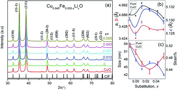
The structural and vibrational studies of Cu0.945Fe0.055−xLixO (0 ≤ x ≤ 0.055) nanoparticles have been examined with XRD and Raman spectroscopy. Note that the Cu content has been kept fixed while the ratio of Fe to Li content has been varied, i.e. Fe has been substituted by Li.X-ray diffraction (XRD) patterns shown in Fig. 1(a) reveal monoclinic crystalline phase of Cu0.945Fe0.055−xLixO (0 ≤ x ≤ 0.055) nanoparticles. All the samples are single phase. No peak belonging to impurity phases is detected. Le Bail profile fitting of XRD data was performed. Lattice parameters a, b and c are smaller for x = 0, i.e. entirely Fe-substitution, than pure CuO. With nominal amount of Li1+ introduction, for x = 0.012, a, b, and c increase to values even more than that of pure CuO and thereafter decrease gradually with increased substitution to values close to pure CuO [Fig. 1(b)]. The crystallite size decreases with increasing x and is much smaller than pure CuO and purely Fe-substituted CuO [Fig. 1(c)]. This emphasizes that Fe and Li are incorporated in monoclinic structure of CuO. The average crystallite size, D, (∼40–50 nm) and lattice strain (∼0.48%) is estimated from the FWHM of prominent diffraction peak (11![[1 with combining macron]](https://www.rsc.org/images/entities/char_0031_0304.gif) ), using Scherrer equation after subtracting the instrumental broadening, D = 0.9λ/β
), using Scherrer equation after subtracting the instrumental broadening, D = 0.9λ/β![[thin space (1/6-em)]](https://www.rsc.org/images/entities/char_2009.gif) cos
cos![[thin space (1/6-em)]](https://www.rsc.org/images/entities/char_2009.gif) θ [where, λ(Cuα1) = 1.5406 Å, λ(Cuα2) = 0.15418 Å, β = line broadening at half the maximum intensity (FWHM) and, θ = Bragg diffraction angle]. FESEM images of Cu0.945Fe0.055−xLixO (0 ≤ x ≤ 0.055) powders [Fig. 2(a)–(d)] reveal particles of sizes ∼100–200 nm and is likely to be composed of several crystallites. With increasing x, the morphology of samples change from elongated to spherical ones. The strain reduced from pure CuO to x = 0.027 sample and increased somewhat thereafter. The strain and disorder created due to the substitution of Fe by Li has two competing mechanisms involved. Note that Li1+(IV) has slightly higher crystal radii ∼0.73 Å (Shannon radii) than Cu2+(IV) ∼ 0.71 Å and Fe3+(IV) ∼ 0.63 Å. The higher charge and lower crystal radius of Fe3+ facilitates O-content to increase thereby removing oxygen deficiency and even introducing oxygen interstitials. On the other hand the increasing substitution by the larger size but with lesser charge Li1+ ion tends to reduce the oxygen content and restore the actual size of the ion at the Cu-site. No doubt this substitution not only controls oxygen content, but also introduces a lot of combinations of exchange interactions between cations, oxygen and oxygen vacancies. Such modifications and introduction of different exchange integrals will provide rich magnetic properties of these materials.
θ [where, λ(Cuα1) = 1.5406 Å, λ(Cuα2) = 0.15418 Å, β = line broadening at half the maximum intensity (FWHM) and, θ = Bragg diffraction angle]. FESEM images of Cu0.945Fe0.055−xLixO (0 ≤ x ≤ 0.055) powders [Fig. 2(a)–(d)] reveal particles of sizes ∼100–200 nm and is likely to be composed of several crystallites. With increasing x, the morphology of samples change from elongated to spherical ones. The strain reduced from pure CuO to x = 0.027 sample and increased somewhat thereafter. The strain and disorder created due to the substitution of Fe by Li has two competing mechanisms involved. Note that Li1+(IV) has slightly higher crystal radii ∼0.73 Å (Shannon radii) than Cu2+(IV) ∼ 0.71 Å and Fe3+(IV) ∼ 0.63 Å. The higher charge and lower crystal radius of Fe3+ facilitates O-content to increase thereby removing oxygen deficiency and even introducing oxygen interstitials. On the other hand the increasing substitution by the larger size but with lesser charge Li1+ ion tends to reduce the oxygen content and restore the actual size of the ion at the Cu-site. No doubt this substitution not only controls oxygen content, but also introduces a lot of combinations of exchange interactions between cations, oxygen and oxygen vacancies. Such modifications and introduction of different exchange integrals will provide rich magnetic properties of these materials.
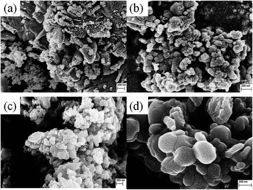 | ||
| Fig. 2 Represents the FESEM images of Cu0.945Fe0.055−xLixO (a) x = 0, (b) x = 0.027, (c) x = 0.043, and (d) x = 0.055. | ||
Raman spectroscopy was done in the range of 200–800 cm−1. In CuO, 4Au + 5Bu are IR active and Ag + 2Bg are Raman active modes.34 Raman active modes (Ag, Bg, and Bg) appear at ∼293, 342 and 628 cm−1 respectively35,36 for all samples [Fig. 3]. No extra vibrational modes are observed ensuring the phase purity and good crystallinity of the samples. We observe a nominal blue shift in all samples with non-zero values of x. This may be due to the reduced effective oscillator mass with Li incorporation. Only for x = 0 we observe a red shift from the pure CuO which may be related to reduction of oxygen vacancies.
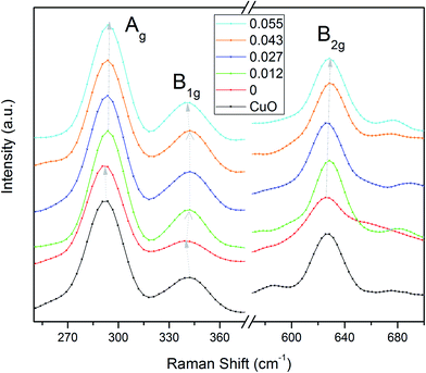 | ||
| Fig. 3 Room temperature Raman spectra of Cu0.945Fe0.055−xLixO. The Raman shift is observed in all Raman modes with increase in x. | ||
The valence state of the Cu, O, Li and Fe ions of the Cu0.945Fe0.055−xLixO (0 ≤ x ≤ 0.055) has been examined by high resolution XPS [Fig. 4]. Adventitious carbon was observed from the presence of C 1s feature. Nominal changes are observed in the binding energies of the Cu 2p3/2 (933.75 eV) and Cu 2p1/2 (953.23 eV) peaks [Fig. 4(b)] in all the substituted samples, consistent with previous reports.35,36 Here, we have shown XPS spectra for x = 0.027. A satellite peak is observed at ∼8.88 eV above the major peak (Cu 2p3/2). This peak is characteristic of materials like copper halides, having open shell 3d9 L (L for ligand) configuration,37 i.e. Cu exists as Cu2+ state with an incomplete d-shell. The incomplete d-shell leads to the satellite peak. The full filled d-shell as in Cu2O containing Cu1+ ions is not associated with a satellite feature [Fig. 4(b)]. Thus presence of any Cu1+ phase in our sample is ruled out.
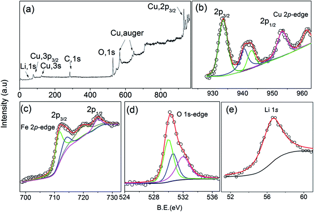 | ||
| Fig. 4 (a) The full survey spectrum, fitted XPS spectra at the (b) Cu 2p (c) Fe 2p (d) O 1s and (e) Li 1s edges of Cu0.945Fe0.027Li0.027O. | ||
A Fe 2p doublet (Fe 2p1/2 and Fe 2p3/2) is observed at ∼723 eV and ∼710 eV, respectively in the Fe 2p spectrum [Fig. 4(c)] of all the Cu0.945Fe0.055−xLixO samples. Due to spin–orbit coupling, splitting of 12.7 eV is observed in Fe 2p spectra. A shake-up satellite feature is observed at about 717.59 eV which is in close agreement with available literature, indicating that Fe is in +3 valence state.35 There is no peak in the region 706–707 eV, indicating the absence of metallic Fe.
A broad peak corresponding to O 1s [Fig. 4(d)] was fitted with three components, at 532.7, 531.4, and 530.13 eV. The lower binding energy peak positioned at 530.13 can be attributed to O2− ion in CuO.38,39 The peak appearing at 532.4 generally corresponds to the adsorbed H2O, or O2.38,39 However, a peak at 531.4 eV has also been observed which is related to oxygen deficient CuO materials.39 Hence, we may say that O2 is less likely to be adhered to the surface and is also deficient in the lattice. Chances of H2O adsorption cannot be ruled out from these data. A peak ∼56 eV [Fig. 4(e)] is in proximity to Li 1s edges reported in other Li containing materials.40,41 Interstitial Li ions in CuO are reported as a significant peak at 52 eV.40,41 We do not see any signature of such a feature in our samples. This emphasizes that Li has substituted Cu in the lattice.
Soft X-ray absorption spectroscopy (SXAS) of Cu0.945Fe0.055−xLixO (0 ≤ x ≤ 0.055) samples at the Cu 2p, Fe 2p and O 1s, was performed to investigate the valence state, density of empty/partially filled electronic states and local geometrical structure of the samples.42
We observe two double peaks matching considerably with the peak profile and position of Fe L3 (2p3/2 → 3d) and L2 (2p1/2 → 3d) edges of Fe2O3 [Fig. 5(a)] separated by 20 eV.43 The double peaks of both the L2 and L3 features, are each composed of a low intense peak, A1 (Fe 2p – t2g) and a main peak, A2 (Fe 2p3/2 – eg).44 To be noted that the XAS data of FeO contains only one peak. Thus the double peak nature is a certain signature that Fe is in Fe3+ state. However, small changes in energy positions of the double peaks hint at probable minor deviations in the oxidation state.
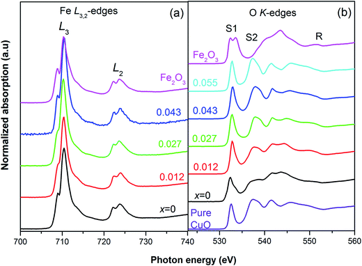 | ||
| Fig. 5 XAS spectra of Cu0.945Fe0.055−xLixO at (a) Fe L2,3-edge with reference to Fe2O3, shows predominantly Fe3+ state, and (b) the O K-edges ensure the phase purity of all samples. | ||
A double peak pre-edge feature due to O 1s → hybridized O(2p)-metal (3deg/t2g) states is reported in Fe2O3;45 S1 (O 1s → Fe 3d – t2g) at ∼531 eV and, S2 (O 1s → Fe3d – teg) at ∼533.6 eV.45,46 The pre-edge is followed by a combination of broad peaks in the range R ∼ 535–555 eV (O 1s → hybridized O (2p)-metal (4s/4p) states.42,45 For the pure CuO sample the XAS data consist of one pre-edge peak, S1 (∼532.6 eV), and R, a region of six other peaks [Fig. 5(b)]. For the substituted Cu0.945Fe0.055−xLixO samples we see similar spectra for most of the samples and the second pre-edge peak, S2, is missing. Note that with the incorporation of Li (x = 0.055) the S1 peak position moves towards slightly higher values suggesting changes in the t2g level of Cu 3d state. Fe is introduced in x = 0.027, 0.043 substituted samples, but the S1 value remains unchanged. The S1 level is highest for x = 0.012. Thereafter, for x = 0, (i.e. 5.5% Fe substitution, containing no Li) the S1 feature moves to a lower energy value at par with the S1 value of Fe2O3. Additionally, a negligibly small hump is observed in close proximity to the position of S2, but not exactly at the S2 position of Fe2O3 (∼533.6 eV). Due to the extra charge of Fe3+, oxygen vacancies are reduced. These extra electrons will be available in the eg levels, thereby a small hump is visible at S2.
The R region shows [Fig. 5(b)] multiple peaks ∼6, corresponding to O 1s → hybridized O 2p-M (4s, 4p) states. There is remarkable resemblance with the CuO features,47 rather than any Fe oxide feature. However, the peak positions are not exactly same as pure CuO. The small changes in the binding energy further confirm substitution and hint at larger separation of energy levels with Li incorporation. The lesser crystal radius of Fe3+ helps in reducing strain in the lattice. But it also introduces more oxygen. With the gradual incorporation of larger size Li1+ ion the trend tries to reverse and strain increased. These types of changes in local strain result in changes in energy levels. However, one must also recollect that the charge of Li1+ is lesser than Fe3+ and Cu2+. Thereby the oxygen retentive properties will be less and the structure will start generating strain due to lattice disorder. Note that for the x = 0 sample, the binding energy has decreased but have increased with even nominal substitution of Li1+.
The normalized Cu K-edge XANES spectra [Fig. 6(a)] of Cu0.945Fe0.055−xLixO (0 ≤ x ≤ 0.055) samples are almost identical with that of pure CuO. A small change in the edge shape and position is observed with Li and Fe incorporation in host lattice. In the CuO K-edges XANES spectra mainly two regions appear.48,49 A shoulder in the energy range of 8982–8986 eV appears and is attributed to a forbidden 1s → 4s transition but allowed due to mixing of 4s and 4p orbitals. This feature is characteristic of Cu2+.50 The main feature appears around 9000 eV is due to the allowed 1s → 4p transition which merges to the continuum.51 No pre-edge peak appears in the XANES spectra in agreement with available literature.52–55 This suggests that Cu ions in Cu0.945Fe0.055−xLixO samples remain in octahedral symmetry.55 To be noted that the energy of the maxima of the white line peaks [Fig. 6(a)] initially decreased and thereafter increased with increase of Li content. These peaks, in the co-doped samples become more intense with substitution. Unfortunately we could not provide the x = 0 sample in this report, but with minimal Li incorporation of x = 0.012 the changes in the intensity was observed. The intensity increased further in x = 0.027 and thereafter started to reduce gradually but was higher than the pure CuO intensity. Hence, from this result it seems that 1s → 4p transition probability increases in Cu ions as Li is introduced and reaches maximum at x = 0.027. This trend is even better observed for the 1s → (4s4p) transition. The shoulder of the absorption edge of the x = 0.027 sample is entirely different from the other samples. To understand better we derived the first derivative of the edges. The derivative shows one minima in between two maxima, the minima corresponding to the energy of transition. It seems that the x = 0.027 sample has the most transition probability for the 1s → 4s4p transition.
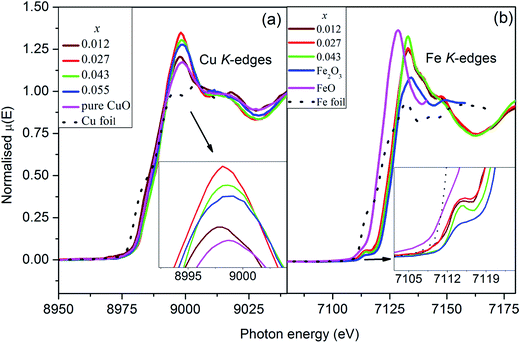 | ||
| Fig. 6 Normalized XANES spectra at (a) Cu K-edges, and (b) Fe K-edges for Cu0.945Fe0.055−xLixO samples showing predominantly Fe3+ substitution at Cu2+ site. | ||
The normalized Fe K-edge XANES spectra of Cu0.945Fe0.055−xLixO samples has been compared with FeO, Fe2O3 and Fe metal foil [Fig. 6(b)]. The spectra of all the samples are identical to that of Fe2O3. However, the edges shifted nominally to relatively lower values. This suggests the possibility of Fe being predominantly in Fe3+ state with nominal Fe2+ presence in all samples. A quantitative analysis of the normalized XANES spectra revealed almost 80–85% Fe3+ oxidation state. A very weak pre-edge feature occurs around the energy of 7112 eV characteristic of Fe3+ (3d5) ion. This corresponds to a transition involving (a) electric quadruple transition, (b) hybridization of the vacant d orbital and (c) the presence of distorted octahedral structure or the little presence of non-centrosymmetric tetrahedral sides.56 In an ideal octahedron where we expect electric dipole moment contributions only such transitions are not seen. Thus the change in the intensity and width in the pre-edge region is the signature of change in the centrosymmetric nature around the absorbing atom. Note that the pre-edge becomes stronger with substitution indicating a stronger distortion in the tetrahedral which indicates possibility of a stronger polarization of the materials [Fig. 6(b)]. Beyond this pre-edge, the main absorption peak around 7127 eV appears due to the 1s → 4p electric dipole transition. There is not much change in the white line intensity between the doped and co-doped samples unlike the case of Cu K-edge XANES.
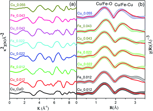
The local atomic structure of Cu0.945Fe0.055−xLixO was investigated with X-ray absorption fine structure (EXAFS) at the Cu and Fe K-edges. The k2-weighted Cu/Fe K-edge EXAFS oscillations and the corresponding Fourier transforms are displayed in Fig. 7(a). The similarities of the χ(R) data of the Cu and Fe K-edges data [Fig. 7(b)], reveal the similarity in local environment in between a Cu and Fe site. The fact that this data matches along with that of pristine CuO, manifests that the structure of CuO is retained in the substituted samples. This indicates that Fe3+ ions are substituting Cu2+ ions without significant distortions in the neighboring shells. This also rules out presence of interstitial Li ions consistent with the XRD, SXAS, XPS and XANES results.
Two dominant peaks, one at ∼1.5 Å (Cu–O scattering path) and the other ∼2.4 Å (Cu–Cu/Fe coordination shell) occur at both Cu and Fe K edge. Theoretical simulation has been done using structural parameters (lattice constants, Wyckoff positions) of monoclinic CuO (space group – C2/c) structure. The theoretical χ(R) vs. R plot along with corresponding scattering paths were generated as previously described model for CuO.25 The set of EXAFS data analysis software available within IFEFFIT package have been used for EXAFS data analysis.33
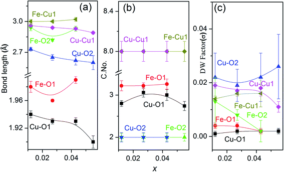
The 1st co-ordination shell having 4 oxygen atoms at 1.95 Å distance contribute to this scattering path and 8 Cu/Fe atoms at 2.90 Å distance in the 3rd co-ordination shell contribute to the next scattering path while the 2 oxygen atoms between these co-ordination shells at 2.78 Å distance contribute very little to this and has higher σ2 value which is a clear evidence of having distorted (Jahn–Teller distortion) octahedral structure. For fitting of the Fe K-edge spectra in the 1st co-ordination shell (Fe–O) same assumption has been taken and it also shows the distorted octahedral structure which agrees with the XANES spectra at the pre-edge region. The second intense peak between 2 and 2.5 Å in the χ(R) versus R plots appears due to scattering from the 8 Cu/Fe atoms at the 3rd shell at a nominal distance of 2.90 Å from the absorbing core atom as also seen in case of Cu K-edge data.
Hence bond distances for both Cu–O and Cu–Cu shells increase with increasing Fe content or decreasing x i.e. Li content [Fig. 8(a)]. The reason for increment in bond distances is the smaller crystal radii of Fe3+(IV) ∼ 0.63 Å than Cu2+(IV) ∼ 0.71 Å. Similar variation in bond lengths were reported in Ni doped ZnO due to difference in crystal radii of Ni2+ and Zn2+.57 So from variations in bond distances, it can be assumed that Fe goes to host CuO lattice as Fe3+. Also, we notice a decrease in atomic distances in Fe–O and Fe–Cu shells due to the reduction in lattice parameter because of the smaller crystal radius of Fe3+ ions (0.63 Å). However, the atomic distances of Fe–O and Fe–Cu, show an expansion compared with that of Cu–O and Cu–Cu in the pure CuO. This is probably due to change in the charge and crystal radii of two species due to Li incorporation.
There is an increment of C. No. of the 1st oxygen shell [Fig. 8(b)] around the central Cu atom with an increase in Fe doping concentration and decreasing Li content to maintain the charge balance with reduction in oxygen vacancies. It should be noted that even at the lowest doping concentration Fe, the oxygen C. No. in the first shell is less than that of theoretical values for monoclinic CuO (which are 4 for the Cu–O1 shell). This is due to the reason that oxygen vacancies exist in pure CuO36 as native defects. However, no change in C. No. of the Cu/Fe–O2 and Cu/Fe–Cu1 shells is observed. The gradual increase of Cu coordination with increasing Fe concentration is attributed to the replacement of Cu2+ ions by Fe3+ ions. The Debye–Waller (σ2) factor of the Cu/Fe–O1 bond is found to be quite low as compared to Cu/Fe–Cu shells which shows lesser disorder around the central atom due to the incorporation of a foreign cation in the lattice. This emphasize on the fact that the 3rd coordination shell (metal–metal) are significantly affected by the doping.
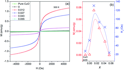
Field dependent magnetism (M–H studies) studies for Cu0.945Fe0.055−xLixO (0 ≤ x ≤ 0.055) samples at room temperature [Fig. 9(a)] seems weak ferromagnetic in nature. The hysteresis loops at room temperature change with substitution. Compared to pure CuO (remnant magnetization = 0.0028 emu g−1), the magnetic moment increases in x = 0 (0.0097 emu g−1) [Fig. 9(b)]. With five d electrons Fe3+ ion has total spin, S = 5/2, whereas Cu2+ ion has 1/2. Fe3+–Cu2+ exchange interaction results in larger magnetic moment than Cu2+–Cu2+. Our investigations (to be published elsewhere) in only Fe-doped samples reveal increasing magnetization with increasing iron content. However, in x = 0.012 magnetic moment is increased drastically to 0.075 emu g−1. This is due to expansion of lattice parameters with nominal Li1+ introduction. Hence lattice expansion leads to stronger ferromagnetic coupling. This is evident from the fact that with further Li1+ substitution, the lattice parameters decrease, thereby decreasing the magnetization. To be noted that Li is replacing Fe, hence for higher x values Fe contribution is less. Finally, for x = 0.055, i.e. only Li1+ substitution, the lattice parameters are even smaller than pure CuO, thereby the magnetic moment is lower than pure CuO. Since Li1+ ion does not have its own d-electrons to interfere with magnetic ordering thereby Li1+ by itself does not contribute to enhance magnetization.
In a similar study on Li co-doping in ZnO![[thin space (1/6-em)]](https://www.rsc.org/images/entities/char_2009.gif) 2, it has been observed that substitutional Li induces a non-spin polarized s-like state. Moreover, electron deficiency at oxygen in the neighborhood of Li induces a charge transfer from electrons at the Fermi level linked with minority spin of late transition metals, thereby increasing the local magnetic moments of late transition metals. Thus, Li co-doping enhances the long range ferromagnetic ordering as it brings the d electron or TM closer for double exchange to be dominated for TM dopants.2 Initially for nominal doping of Li we do see an increment in the magnetic properties which may agree with this explanation. But, in higher Li-doped samples we should expect a higher magnetization due to more Li-assisted exchange mechanisms. However, we see magnetization to decrease. This emphasizes that most probably magnetization is not a Li-mediated but is more dependent on the ionic spin and separation.
2, it has been observed that substitutional Li induces a non-spin polarized s-like state. Moreover, electron deficiency at oxygen in the neighborhood of Li induces a charge transfer from electrons at the Fermi level linked with minority spin of late transition metals, thereby increasing the local magnetic moments of late transition metals. Thus, Li co-doping enhances the long range ferromagnetic ordering as it brings the d electron or TM closer for double exchange to be dominated for TM dopants.2 Initially for nominal doping of Li we do see an increment in the magnetic properties which may agree with this explanation. But, in higher Li-doped samples we should expect a higher magnetization due to more Li-assisted exchange mechanisms. However, we see magnetization to decrease. This emphasizes that most probably magnetization is not a Li-mediated but is more dependent on the ionic spin and separation.
The coercive field, Hc ∼ 25–131 Oe also follows the same trend as remnant magnetization [Fig. 9(b)]. Even at 5000 Oe saturation is not achieved. This trend of gradually changing Hc and MR with substitution further strengthens our claim of proper substitution without an impurity phase at par with XPS and XAS studies.
4. Conclusions
Structural properties of sol–gel prepared monoclinic single phase Cu0.945Fe0.055−xLixO powder samples were systematically studied. Le Bail profile fitting of room temperature XRD data shows nominal changes in lattice parameters; with increasing x, lattice parameters a, b and c first increase for x = 0.012 and thereafter decrease gradually. All fundamental vibration modes of CuO were observed in Raman spectra which confirm the CuO-like structure. The role of Li in generating intrinsic pressure in the lattice due to larger crystal radius was envisaged. From microstructural and Raman data it has been observed that no secondary or clustering phases were found. XPS, SXAS and XANES analysis confirm that Cu2+ sites are substituted mostly by Fe3+. An EXAFS study reveals that the local neighborhood of Fe atoms matches with that of Cu atoms in CuO. Any similarity with oxides of Fe and other complex oxides of Cu and Fe was ruled out. EXAFS data analysis also reveals reduction in oxygen vacancies with increasing Fe content possibly to due to extra charge of Fe3+ than Cu2+ ions within the same structure. Metal–metal interactions are significantly affected by the Li substitution than the metal–oxygen ones. This causes change in the lattice supported by the fact that the Fe–O bonds are longer than Cu–O ones. The observed room temperature ferromagnetic ordering in Cu0.945Fe0.055O is understood through superexchange mechanism. Additional doping of Li (x = 0.012) in Cu0.095Fe0.055O, enhances the magnetic properties. But, in higher Li-doped samples, the magnetization decreases. This emphasizes that most probably magnetization is not a Li-mediated but is more dependent on the ionic spin and separation. The separation is therefore the most likely responsible factor for the variation of magnetism.Acknowledgements
The authors gratefully acknowledge IIT Indore for supporting the project and providing the XRD facility. We gratefully acknowledge Dr Vasant Sathe for providing access to Raman spectroscopy. Md. Nasir is also thankful to UGC, New Delhi, for providing Maulana Azad fellowship. One of authors (S. Biring) acknowledges financial grant received from MOST, Taiwan (105-2218-E-131-003).References
- S. Manna and S. K. De, J. Magn. Magn. Mater., 2010, 322, 2749–2753 CrossRef CAS.
- M. H. F. Sluiter, Y. Kawazoe, P. Sharma, A. Inoue, A. R. Raju, C. Rout and U. V. Waghmare, Phys. Rev. Lett., 2005, 94, 187204 CrossRef PubMed.
- Y. R. Park, K. J. Kim, S.-l. Choi, J. H. Lee, H. J. Lee, C. S. Kim and J. Y. Park, Phys. Status Solidi B, 2007, 244, 4578–4581 CrossRef CAS.
- T. Dietl, H. Ohno, F. Matsukura, J. Cibert and D. Ferrand, Science, 2000, 287, 1019–1022 CrossRef CAS PubMed.
- R. S. Devan, R. A. Patil, J.-H. Lin and Y.-R. Ma, Adv. Funct. Mater., 2012, 22, 3326–3370 CrossRef CAS.
- M. Sieberer, J. Redinger and P. Mohn, Phys. Rev. B: Condens. Matter Mater. Phys., 2007, 75, 035203 CrossRef.
- H. Yanagi, S.-i. Inoue, K. Ueda, H. Kawazoe, H. Hosono and N. Hamada, J. Appl. Phys., 2000, 88, 4159–4163 CrossRef CAS.
- Y. Liu, H. K. Turley, J. R. Tumbleston, E. T. Samulski and R. Lopez, Appl. Phys. Lett., 2011, 98, 162105 CrossRef.
- F. Wang, H. Li, Z. Yuan, Y. Sun, F. Chang, H. Deng, L. Xie and H. Li, RSC Adv., 2016, 6, 79343–79349 RSC.
- M. Wang, F. Xie, W. Xie, S. Zheng, N. Ke, J. Chen and N. Zhao, Appl. Phys. Lett., 2011, 98, 183304 CrossRef.
- J. Pike, S.-W. Chan, F. Zhang, X. Wang and J. Hanson, Appl. Catal., A, 2006, 303, 273–277 CrossRef CAS.
- C. Wang, Q. Li, F. Wang, G. Xia, R. Liu, D. Li, N. Li, J. S. Spendelow and G. Wu, ACS Appl. Mater. Interfaces, 2014, 6, 1243–1250 CAS.
- M.-J. Deng, C.-C. Wang, P.-J. Ho, C.-M. Lin, J.-M. Chen and K.-T. Lu, J. Mater. Chem. A, 2014, 2, 12857–12865 CAS.
- T. Kimura, Y. Sekio, H. Nakamura, T. Siegrist and A. P. Ramirez, Nat. Mater., 2008, 7, 291–294 CrossRef CAS PubMed.
- G. N. Rao, Y. D. Yao and J. W. Chen, J. Appl. Phys., 2009, 105, 093901 CrossRef.
- G. N. Rao, Y. D. Yao and J. W. Chen, J. Appl. Phys., 2007, 101, 09H119 CrossRef.
- C. T. Meneses, J. G. S. Duque, L. G. Vivas and M. Knobel, J. Non-Cryst. Solids, 2008, 354, 4830–4832 CrossRef CAS.
- D. T. Gazioğlu, F. Dumludağ and A. Altindal, AIP Conf. Proc., 2010, 1203, 456–460 CrossRef.
- D. Paul Joseph, C. Venkateswaran, S. Sambasivam and B. C. Choi, J. Korean Phys. Soc., 2012, 61, 449–454 CrossRef CAS.
- Y. Li, M. Xu, L. Pan, Y. Zhang, Z. Guo and C. Bi, J. Appl. Phys., 2010, 107, 113908 CrossRef.
- K. L. Liu, S. L. Yuan, H. N. Duan, X. F. Zheng, S. Y. Yin, Z. M. Tian, C. H. Wang and S. X. Huo, J. Appl. Phys., 2010, 107, 023911 CrossRef.
- S. Yakout and A. El-Sayed, J. Supercond. Novel Magn., 2016, 29, 2961–2968 CrossRef CAS.
- A. Punnoose, H. Magnone, M. S. Seehra and J. Bonevich, Phys. Rev. B: Condens. Matter Mater. Phys., 2001, 64, 174420 CrossRef.
- K. Muraleedharan, C. K. Subramaniam, N. Venkataramani, T. K. Gundu Rao, C. M. Srivastava, V. Sankaranarayanan and R. Srinivasan, Solid State Commun., 1990, 76, 727–730 CrossRef CAS.
- M. Nasir, N. Patra, D. K. Shukla, D. Bhattacharya, S. Kumar, D. M. Phase, S. N. Jha, S. Biring, P. M. Shirage and S. Sen, RSC Adv., 2016, 6, 103571–103578 RSC.
- N. Tiwari, S. Doke, A. Lohar, S. Mahamuni, C. Kamal, A. Chakrabarti, R. J. Choudhary, P. Mondal, S. N. Jha and D. Bhattacharyya, J. Phys. Chem. Solids, 2016, 90, 100–113 CrossRef CAS.
- T. Kataoka, Y. Yamazaki, V. R. Singh, Y. Sakamoto, A. Fujimori, Y. Takeda, T. Ohkochi, S.-I. Fujimori, T. Okane, Y. Saitoh, H. Yamagami, A. Tanaka, M. Kapilashrami, L. Belova and K. V. Rao, Appl. Phys. Lett., 2011, 99, 132508 CrossRef.
- H.-T. Lin, T.-S. Chin, J.-C. Shih, S.-H. Lin, T.-M. Hong, R.-T. Huang, F.-R. Chen and J.-J. Kai, Appl. Phys. Lett., 2004, 85, 621–623 CrossRef CAS.
- K. Sato and H. Katayama-Yoshida, Phys. Status Solidi B, 2002, 229, 673–680 CrossRef CAS.
- M. Nasir, G. Kumar, P. M. Shirage and S. Sen, J. Nanosci. Nanotechnol., 2017, 17, 1345–1349 CrossRef.
- S. Basu, C. Nayak, A. K. Yadav, A. Agrawal, A. K. Poswal, D. Bhattacharyya, S. N. Jha and N. K. Sahoo, J. Phys.: Conf. Ser., 2014, 493, 012032 CrossRef.
- A. K. Poswal, A. Agrawal, A. K. Yadav, C. Nayak, S. Basu, S. R. Kane, C. K. Garg, D. Bhattachryya, S. N. Jha and N. K. Sahoo, AIP Conf. Proc., 2014, 1591, 649–651 CrossRef CAS.
- M. Newville, B. Ravel, D. Haskel, J. J. Rehr, E. A. Stern and Y. Yacoby, Phys. B, 1995, 208, 154–156 CrossRef.
- J. F. Xu, W. Ji, Z. X. Shen, W. S. Li, S. H. Tang, X. R. Ye, D. Z. Jia and X. Q. Xin, J. Raman Spectrosc., 1999, 30, 413–415 CrossRef CAS.
- U. K. Gaur, A. Kumar and G. D. Varma, J. Mater. Chem. C, 2015, 3, 4297–4307 RSC.
- D. Gao, G. Yang, J. Li, J. Zhang, J. Zhang and D. Xue, J. Phys. Chem. C, 2010, 114, 18347–18351 CAS.
- G. van der Laan, C. Westra, C. Haas and G. A. Sawatzky, Phys. Rev. B: Condens. Matter Mater. Phys., 1981, 23, 4369–4380 CrossRef CAS.
- B. Pandey, S. Ghosh, P. Srivastava, P. Kumar, D. Kanjilal, S. Zhou and H. Schmidt, J. Appl. Phys., 2010, 107, 023901 CrossRef.
- M. A. Dar, Y. S. Kim, W. B. Kim, J. M. Sohn and H. S. Shin, Appl. Surf. Sci., 2008, 254, 7477–7481 CrossRef CAS.
- K. P. Yao, D. G. Kwabi, R. A. Quinlan, A. N. Mansour, A. Grimaud, Y.-L. Lee, Y.-C. Lu and Y. Shao-Horn, J. Electrochem. Soc., 2013, 160, A824–A831 CrossRef CAS.
- R. S. Watkins, A. F. Lee and K. Wilson, Green Chem., 2004, 6, 335–340 RSC.
- F. M. F. de Groot, M. Grioni, J. C. Fuggle, J. Ghijsen, G. A. Sawatzky and H. Petersen, Phys. Rev. B: Condens. Matter Mater. Phys., 1989, 40, 5715–5723 CrossRef CAS.
- S. Kumar, Y. J. Kim, B. H. Koo, S. K. Sharma, J. M. Vargas, M. Knobel, S. Gautam, K. H. Chae, D. K. Kim, Y. K. Kim and C. G. Lee, J. Appl. Phys., 2009, 105, 07C520 CrossRef.
- P. Kuiper, B. G. Searle, P. Rudolf, L. H. Tjeng and C. T. Chen, Phys. Rev. Lett., 1993, 70, 1549–1552 CrossRef CAS PubMed.
- A. Malakar, B. Das, S. Islam, C. Meneghini, G. De Giudici, M. Merlini, Y. V. Kolen'ko, A. Iadecola, G. Aquilanti, S. Acharya and S. Ray, Sci. Rep., 2016, 6, 26031 CrossRef CAS PubMed.
- L. A. Grunes, R. D. Leapman, C. N. Wilker, R. Hoffmann and A. B. Kunz, Phys. Rev. B: Condens. Matter Mater. Phys., 1982, 25, 7157–7173 CrossRef CAS.
- A. B. Gurevich, B. E. Bent, A. V. Teplyakov and J. G. Chen, Surf. Sci., 1999, 442, L971–L976 CrossRef CAS.
- J. L. DuBois, P. Mukherjee, T. D. P. Stack, B. Hedman, E. I. Solomon and K. O. Hodgson, J. Am. Chem. Soc., 2000, 122, 5775–5787 CrossRef CAS.
- R. A. Bair and W. A. Goddard, Phys. Rev. B: Condens. Matter Mater. Phys., 1980, 22, 2767–2776 CrossRef CAS.
- S. E. Shadle, J. E. Penner-Hahn, H. J. Schugar, B. Hedman, K. O. Hodgson and E. I. Solomon, J. Am. Chem. Soc., 1993, 115, 767–776 CrossRef CAS.
- A. Sharma, M. Varshney, J. Park, T.-K. Ha, K.-H. Chae and H.-J. Shin, RSC Adv., 2015, 5, 21762–21771 RSC.
- P. Bera, K. R. Priolkar, P. R. Sarode, M. S. Hegde, S. Emura, R. Kumashiro and N. P. Lalla, Chem. Mater., 2002, 14, 3591–3601 CrossRef CAS.
- X. Wang, J. C. Hanson, A. I. Frenkel, J.-Y. Kim and J. A. Rodriguez, J. Phys. Chem. B, 2004, 108, 13667–13673 CrossRef CAS.
- S. Velu, K. Suzuki, C. S. Gopinath, H. Yoshida and T. Hattori, Phys. Chem. Chem. Phys., 2002, 4, 1990–1999 RSC.
- P. Khemthong, P. Photai and N. Grisdanurak, Int. J. Hydrogen Energy, 2013, 38, 15992–16001 CrossRef CAS.
- M. L. Fdez-Gubieda, A. Muela, J. Alonso, A. García-Prieto, L. Olivi, R. Fernández-Pacheco and J. M. Barandiarán, ACS Nano, 2013, 7, 3297–3305 CrossRef CAS PubMed.
- M. Deepak, P. Chinmay, B. Sohini, P. Arjun, D. Igor, A. Naushad, S. N. Jha, D. Bhattachryya and M. Shailaja, J. Phys. D: Appl. Phys., 2014, 47, 045308 CrossRef.
| This journal is © The Royal Society of Chemistry 2017 |

