
 Open Access Article
 This Open Access Article is licensed under a
 Creative Commons Attribution 3.0 Unported Licence
Topological relations and piezoelectric responses of crystal-axis-oriented BaTiO3/CaTiO3 nanocomposites†
Dengwei Hu *a,
Xiaomei Niua,
Hao Mab,
Wenxiong Zhangb,
Galhenage A. Sewvandic,
Desuo Yanga,
Xiaoling Wanga,
Hongshei Wanga,
Xingang Kongd and
Qi Feng*b
*a,
Xiaomei Niua,
Hao Mab,
Wenxiong Zhangb,
Galhenage A. Sewvandic,
Desuo Yanga,
Xiaoling Wanga,
Hongshei Wanga,
Xingang Kongd and
Qi Feng*b
aCollege of Chemistry and Chemical Engineering, Engineering Research Center of Advanced Ferroelectric Functional Materials, Key Laboratory of Phytochemistry of Shaanxi Province, Baoji University of Arts and Sciences, 1 Hi-Tech Avenue, Baoji, Shaanxi, 721013 P. R. China. E-mail: hdwpolymer@yahoo.co.jp; Fax: +86-917-356-6366; Tel: +86-917-356-6589
bDepartment of Advanced Materials Science, Faculty of Engineering, Kagawa University, 2217-20 Hayashi-cho, Takamatsu-shi, 761-0396 Japan. E-mail: feng@eng.kagawa-u.ac.jp; Fax: +81-87-864-2438; Tel: +81-87-864-2402
cDepartment of Materials Science and Engineering, Faculty of Engineering, University of Moratuwa, Katubedda, Sri Lanka
dSchool of Materials Science and Engineering, Shaanxi University of Science and Technology, Weiyang, Xi'an, Shaanxi, 710021 P. R. China
First published on 14th June 2017
Abstract
2D crystal-axis-oriented mesocrystalline BaTiO3/CaTiO3 (BT/CT) nanocomposites with high-density heteroepitaxial interfaces were synthesized by a two-step solvothermal soft chemical process. The nanostructures, formation mechanism, topological relations between the BT and CT, and piezoelectric responses of the nanocomposites were investigated. The mesocrystalline nanocomposites are polycrystals constructed from crystal-axis-oriented BT and CT nanocrystals with the same crystal-axis orientation, respectively. The directions of the [001] and [1−10] of crystalline BT correspond to the directions of the [0−10] and [100] of crystalline CT, respectively. The mesocrystalline nanocomposites were formed via an in situ topochemical mesocrystal conversion mechanism. The density of the artificial BT/CT heteroepitaxial interface in these mesocrystalline nanocomposites can be adjusted by regulating the fraction of BT and CT in the nanocomposites. The mesocrystalline BT/CT nanocomposite with the composition close to BT/CT = 1/1 presents a large piezoelectric response owing to the lattice strain derived from its heteroepitaxial interfaces with the high density in the nanocomposite.
1 Introduction
Advances in atomic-level control of the heteroepitaxial nanostructures of functional nanocomposite materials have focused on the enhancement of the electrical properties of multicomponent metal oxide perovskites.1–4 A lattice strain in such perovskites can effectively produce a high strain energy derived from the lattice mismatch sustained at their heteroepitaxial interfaces.1,3,5,6 The high-density lattice strain at the heteroepitaxial interfaces is very beneficial for a large enhancement in the electrical properties.3,7,8 Among the studies on nanocomposite perovskites with heteroepitaxial interfaces, BaTiO3/SrTiO3 (BT/ST) and BiFeO3-based nanomaterials have been developed mainly by molecular beam epitaxy (MBE) and electrochemical deposition processes.2–4,9,10 But these fabrication processes are complicated and expensive stacking configurations.11,12 Therefore, the design of a new process to develop nanostructures with high-density heteroepitaxial interfaces is highly anticipated. However, nanostructures with high-density heteroepitaxial interfaces are difficult to obtain by traditional methods.Mesocrystal is a polycrystal constructed from crystal-axis-oriented nanocrystals,13 in which each oriented nanocrystal presents the same orientation direction. The electron diffraction pattern of a mesocrystal shows spots corresponding to the reciprocal lattice points as a single crystal.14 It not only has properties based on the individual nanocrystal, but also exhibits unique collective properties and advanced tunable functions.15,16 It can offer unique new opportunities for materials design.13,17 Some 2D titanate mesocrystals were developed by our previous works.18–22 Recently, we have reported that a mesocrystalline BT/ST nanocomposite with a mole ratio of Ba/Sr = 1 shows a remarkable enhancement of piezoelectric response by the BT/ST heteroepitaxial interface in the nanocomposite.23 In the mesocrystalline BT/ST nanocomposite, tetragonal BT is a ferroelectric phase and cubic ST is a paraelectric phase. Although the CaTiO3 (CT) and ST are alkaline earth metal titanates, there are some obvious lattice differences between them. The artificial construction of lattice strain from the heteroepitaxial interface between these titanates can be realized. Therefore, the replacement of cubic ST by using orthorhombic CT is a new challenge and may be an effective method for the further enhancement of piezoelectric response.
In this report, we present a two-step solvothermal soft chemical process to synthesize 2D crystal-axis-oriented mesocrystalline BaTiO3/CaTiO3 (BT/CT) nanocomposites with artificial heteroepitaxial interfaces for the first time. The obtained 2D mesocrystalline BT/CT nanocomposites are polycrystals constructed from well-aligned BT and CT nanocrystals with the same orientation direction. Such 2D mesocrystal is very difficult to be obtained via the conventional self-assembly approach owing to their high orientation, high aspect ratio of two-dimension, and the chemical composition of two components. The topological relations between the crystal-axis-oriented BT and CT nanocrystals were investigated. The correlation between the piezoelectric response of and composition for the mesocrystalline nanocomposites has been revealed. Our findings imply a possibility of the simultaneous applications of the orientation engineering and the strain engineering to approach a huge piezoelectric response effect by using the characteristics of the mesocrystalline materials.
2 Experimental section
Sample preparation
All reagents used in this study were of analytical grade and without further purification. 2D single crystal precursors (thickness ∼ 200 nm) of H4x/3Ti2−x/3□x/3O4·nH2O (□: vacancy of Ti, x = 0.8, n = 1, abbreviated as HT) with layered lepidocrocite structure were prepared as reported in our previous study.24 Anatase TiO2 nanoparticles (6.9 g), 5.1 g of KOH, 0.6 g of LiOH·H2O, and 25 mL of distilled water were sealed into a Hastelloy-C-lined vessel with internal volume of 45 mL and then heated at 250 °C for 24 h under stirring conditions. After the hydrothermal treatment, the obtained sample was washed with distilled water and dried at room temperature to obtain K0.80Ti1.73Li0.27O4·xH2O (KTLO) crystals. The KTLO crystals (10.0 g) were treated with a 0.2 mol L−1 HNO3 solution (1 L) for 24 h under stirring conditions to exchange K+ and Li+ in the layered structure with H+, and then the sample was washed with distilled water. After the acid treatments were done twice, the layered protonated titanate HT single crystals were obtained. The as-obtained crystals were collected and washed with distilled water and alcohol, before air-drying at 60 °C for 6 h, and then the HT (6.2 g) single crystal precursors were obtained.For the synthesis of the platelike crystal-axis-oriented mesocrystalline BaTiO3/CaTiO3 (BT/CT) nanocomposite, one-step solvothermal process was firstly tried by solvothermal treatments of HT (0.096 g)-Ba(OH)2–Ca(OH)2 mixture with different molar ratios of Ti/Ba/Ca in 30 mL solution using a sealed stainless-steel vessel with inner volume of 75 mL under different conditions. The pure BT/CT mixed phases cannot be obtained but some mixtures (see the ESI:† (1) one-step solvothermal soft chemical process). Therefore, we designed a two-step solvothermal soft chemical process for the preparation of the BT/CT nanocomposites. This process is gentle to keep the morphology of the starting matrix and is conducive to topochemical conversion reaction. In the first step, the HT precursors (0.096 g) were reacted partially with 30 mL Ba(OH)2 solutions (mole ratio of Ti/Ba = 4![[thin space (1/6-em)]](https://www.rsc.org/images/entities/char_2009.gif) :1, 2:1, 3:2, and 7:6, respectively) in a Teflon-lined, sealed stainless-steel vessel with inner volume of 75 mL at 200 °C for 12 h, to obtain the BaTiO3/HT (BT/HT-1/3, -1/1, -2/1, -6/1) nanocomposites. The 2D homogeneous BT/HT nanocomposites generated in the water solvent were employed as precursors in the next step. In the second step, the generated homogeneous BT/HT nanocomposites were solvothermally treated at 200 °C for 12 h in 30 mL Ca(OH)2 suspensions with the different concentration. A water–ethanol mixed solvent with a volume ratio of 5:25 was employed for the dispersion of the Ca(OH)2 in the second step. To drive the reaction to completion, it is necessary that the excess 50% of Ca was placed in the reaction system. After the solvothermal treatment, the obtained sample was sequentially washed with the 0.2 mol L−1 acetic acid solution, distillated water, and ethanol. Finally, the obtained sample was dried at 60 °C for 12 h. The samples generated in the second step were designated as BT/CT-x/y, where x/y is a mole ratio of Ba/Ca. Therefore, the samples of the BT/CT-1/3, BT/CT-1/1, BT/CT-2/1, and BT/CT-6/1 were prepared from BT/HT-1/3, -1/1, -2/1, -6/1 samples, respectively.
:1, 2:1, 3:2, and 7:6, respectively) in a Teflon-lined, sealed stainless-steel vessel with inner volume of 75 mL at 200 °C for 12 h, to obtain the BaTiO3/HT (BT/HT-1/3, -1/1, -2/1, -6/1) nanocomposites. The 2D homogeneous BT/HT nanocomposites generated in the water solvent were employed as precursors in the next step. In the second step, the generated homogeneous BT/HT nanocomposites were solvothermally treated at 200 °C for 12 h in 30 mL Ca(OH)2 suspensions with the different concentration. A water–ethanol mixed solvent with a volume ratio of 5:25 was employed for the dispersion of the Ca(OH)2 in the second step. To drive the reaction to completion, it is necessary that the excess 50% of Ca was placed in the reaction system. After the solvothermal treatment, the obtained sample was sequentially washed with the 0.2 mol L−1 acetic acid solution, distillated water, and ethanol. Finally, the obtained sample was dried at 60 °C for 12 h. The samples generated in the second step were designated as BT/CT-x/y, where x/y is a mole ratio of Ba/Ca. Therefore, the samples of the BT/CT-1/3, BT/CT-1/1, BT/CT-2/1, and BT/CT-6/1 were prepared from BT/HT-1/3, -1/1, -2/1, -6/1 samples, respectively.
For comparison purposes, the pure BT and CT mesocrystals without any heteroepitaxial interfaces were respectively prepared in pure water solvent from the HT precursor at 200 °C for 12 h via the solvothermal soft chemical process as reported by us previously also.18,20 Although the platelike CT mesocrystals cannot be easily formed completely in this process,20 a small number of CT mesocrystals with platelike morphology can be selected out easily and contrasted to the other titanates in this study.
Physical analysis
The structures of the crystalline samples were investigated using a powder X-ray diffractometer (XRD) (Shimadzu, XRD-6100; Rigaku, D/max-Ultima IV) with Cu Kα (λ = 0.15418 nm) radiation. The size and morphology of the crystalline samples were observed using scanning electron microscopy (SEM) (JEOL, JSM-5500S) or field emission scanning electron microscopy (FESEM) (Hitachi, S-900) or environment scanning electron microscopy (ESEM) (FEI, Quanta 250 FEG). Transmission electron microscopy (TEM)/(high-resolution TEM (HRTEM)) observation and selected-area electron diffraction (SAED) were performed on a JEOL Model JEM-3010 system at 300 kV, and the crystalline samples were supported on a Cu microgrid. Energy-dispersive spectroscopy (EDS; JEOL JED-2300T) was measured on the TEM system. Energy dispersive spectroscopy mapping (EDS-mapping) was observed using a combined HRTEM-EDS system (JEOL Model JEM-2100F HRTEM/EX-24063JGT EDX) as a function of the local relative concentration of the elements present.Piezoelectric responses were measured by a scanning probe microscopy (SPM) system on a combined atomic force microscope (AFM) and piezoresponse force microscopy (PRM) systems (SII, NanoTechnology Inc., Nano Navi Station; Bruker, Dimension Icon) with an SPA-400 probe. Silicon micro cantilever (SI-DF3-R, R: Rh precoated, f = 28 kHz, c = 42 N m−1) and SiO2/Si substrate were coated with an approximate 20 nm Au thin film by ion sputtering. The samples were dispersed on the Au thin film by drop casting. The location of an individual mesocrystal was detected by the conductive AFM probe tip with a conductive Au-coated Rh-precoated Si cantilever in the contact mode. After that a bias from −10 to 10 V was applied to the surface of the mesocrystal, and the information of the strains of the mesocrystal was gathered at the same time and detected from the global deflection signal using a built-in lock-in amplifier connected to the AFM. The effective piezoelectric coefficient  value was calculated by the formula

3 Results and discussions
Characterization of samples
:3 and 6:1, respectively, the diffraction intensities of CT and BT phases present a very strong contrast (Fig. 1a and d); namely, one is strong and another is feeble. When the mole ratios of Ba/Ca is 1:1 and the pure ethanol was employed as the reaction solvent, pure BT/CT mixed phases cannot be obtained but a complicated mixture including anatase (ICDD file no. 21-1272), abundant BT, trace amounts of CT, unreacted HT and Ca(OH)2 (ICDD file no. 84-1272) (Fig. 1e). These results imply that the pure BT/CT mixed phases can be obtained by the solvothermal treatment of the homogeneous BT/HT nanocomposites in the water–ethanol mixed solvent. The composition of BT and CT in the mixtures can be controlled by the instruction of BT contents.
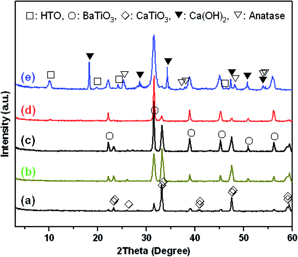 | ||
| Fig. 1 XRD patterns of samples of (a) BT/CT-1/3, (b and e) BT/CT-1/1, (c) BT/CT-2/1, and (d) BT/CT-6/1 obtained by solvothermal treatments of different BT/HT nanocomposites and Ca(OH)2 in (a–d) water–ethanol mixed solvent with volume ratio of 5:25 and (e) pure ethanol solvent at 200 °C for 12 h, respectively. | ||
 | ||
| Fig. 2 FESEM images of samples of (a) BT/CT-1/3, (b) BT/CT-1/1, (c) BT/CT-2/1, and (d) BT/CT-6/1 obtained by solvothermal treatments of different BT/HT nanocomposites and Ca(OH)2 in water–ethanol mixed solvent with volume ratio of 5:25 at 200 °C for 12 h, respectively. | ||
 | ||
| Fig. 3 (a, d, g and j) TEM images, (b, e, h and k) SAED patterns, and (c, f, i and l) HRTEM images of (a, b and c) BT/CT-1/3, (d, e and f) BT/CT-1/1, (g, h and i) BT/CT-2/1, and (j, k and l) BT/CT-6/1 samples obtained by solvothermal treatments of different BT/HT nanocomposites and Ca(OH)2 in water–ethanol mixed solvent with volume ratio of 5:25 at 200 °C for 12 h, respectively. (c, f, i and l) HRTEM images derived from the (c, f, i and l) white panes in (a, d, g and j) TEM images, respectively. The inserted FFT (Fast Fourier Transformation) patterns derived from whole region of the corresponding HRTEM images, respectively. The blue lines in HRTEM images indicate the boundary regions between two primary nanocrystals. | ||
In the HRTEM images (Fig. 3c, f, i and j), the lattice fringes of 0.396–0.399 nm (Fig. 3f1 and f2) and 0.282 nm (Fig. 3i) correspond to the (001) and (1−10) plane of the BT phase, respectively. The directions of the planes are consistent with the results in Fig. 3e and h, respectively. The lattice fringes of 0.381–0.382 nm (Fig. 3c and f2) and 0.273 (Fig. 3i) nm correspond to the (0−20) and (200) plane of the CT phase, respectively. The directions of the planes are consistent with the results in Fig. 3b, e and h as well, respectively. The lattice fringes of the (001) and (1−10) plane of the BT phase are obviously close to the (0−20) and (200) plane of the CT phase, respectively, which can provide an evidence for the formation of the BT/CT heteroepitaxial interface in the nanocomposites. Such close lattice fringes can easily form the lattice strain. Their FFT patterns (inserted in Fig. 3c, i and l) agree with the corresponding SAED patterns in Fig. 3b, h and k, respectively. The crystal boundary regions indicated by the blue lines between BT and CT primary nanocrystals in a mesocrystal can be observed directly in the HRTEM images (Fig. 3f2, i and l). These results described above reveal the obtained BT/CT hybrids are 2D crystal-axis-oriented nanocomposites. The nanocomposites are polycrystals constructed from well-aligned BT and CT nanocrystals. A confirmable topological relations between the BT and CT in the nanocomposites. The directions of the [001], [1−10] and [110] of crystalline BT correspond to the directions of the [0−10], [100], and [001] of crystalline CT, respectively. Such nanocomposites are 2D mesocrystalline nanocomposites with a high-density heteroepitaxial nanostructure.
 | ||
| Fig. 4 (A) EDS spectra of (a) BT/CT-1/3, (b) BT/CT-1/1, (c) BT/CT-2/1, and (d) BT/CT-6/1 samples obtained by solvothermal treatments of different BT/HT nanocomposites and Ca(OH)2 in water–ethanol mixed solvent with volume ratio of 5:25 at 200 °C for 12 h, respectively. (B) EDS-mapping TEM images of BT/CT-1/1 sample. | ||
Formation mechanism of the mesocrystalline BT/CT nanocomposite
Based on the description above and the results (Fig. 1–4) in the original text, a schematic representation of an in situ topochemical mesocrystal conversion mechanism from the layered HT single crystal precursor to the mesocrystalline BT/CT nanocomposite can be illustrated in Fig. 5. Before reaction, in the crystal structure of the layered HT lepidocrocite, the host sheets are stacked with a basal spacing of about 0.882 nm in a body-centered orthorhombic system, accommodating H2O and H3O+ between them.24 In the first step, the partial HT crystal is transformed into BT nanocrystals because the Ti/Ba mole ratio in the reaction system is less than 1. Initially, Ba2+ are intercalated into the HT bulk crystal through its interlayer pathway by an H+/Ba2+ exchange reaction, and then the Ba2+ react with the TiO6 octahedral layers of HT in the bulk crystal to form the BT phase.19 Therefore, the 2D BT/HT nanocomposites formed by this reaction have uniform distributions of BT nanoparticles in the bulk crystals. In the present case, the topochemical conversion reaction is dominant in the water solvent, owing to the low concentration of Ba(OH)2.18,22 In the second step of the solvothermal treatment of the BT/HT nanocomposite in the Ca(OH)2 suspensions, another topochemical conversion reaction occurs similar to the first step. In this step, incipiently, the Ca2+ are intercalated into the residual HT matrix crystal through the interlayer pathway by an H+/Ca2+ exchange reaction, and then the Ca2+ react with the unreacted HT matrix crystal to form the CT nanocrystals until consuming all the HT phase. Because the generated BT nanocrystals are well-aligned and show the same direction orientation,23 the CT nanocrystals generated against the BT nanocrystals and grew by a heteroepitaxial growth process, resulting in the topochemical formation of the crystal-axis-oriented mesocrystalline BT/CT nanocomposite with heteroepitaxial nanostructure, which is different from the formation mechanism of oriented attachment.28 There is a definite crystallographic topological relationship between the crystal-axis directions of the oriented BT and CT nanocrystals (see Fig. 5) existing in the mesocrystalline BT/CT nanocomposite homogeneously. The directions of the [001], [110], and [1−10] of BT correspond to the directions of the [0−20], [001], and [200] of CT, respectively (see Fig. 5). In addition, the chemical composition distributions in these 2D mesocrystalline BT/CT nanocomposites are uniform. Therefore, such 2D mesocrystalline BT/CT nanocomposites own stacking nanostructure and high-density heteroepitaxial interface. | ||
| Fig. 5 Schematic representation of crystallographic variation of crystalline structure from layered HT single crystal to mesocrystalline BaTiO3/CaTiO3 nanocomposite via in situ topochemical mesocrystalline conversion reaction. | ||
Piezoelectric responses of the mesocrystals
The piezoelectric responses of the individual platelike particles of the mesocrystalline BT/CT nanocomposites were recorded by a scanning probe microscopy (SPM) system. Fig. 6a and S6 (see (4) piezoelectric response in the ESI†) illustrate the typical butterfly loops of electric-field-induced displacements for individual mesocrystals obtained by the two-step solvothermal soft chemical process, and the converse piezoelectric coefficients were also calculated and labeled to the right axis. The long-term piezoelectric responses can be confirmed by the PRM systems though the examination is exposed to a higher number of applied voltage cycles. The performance test is repeated for 6 times, showing good repetitiveness. The value in this study is an average value. The BT/CT-x/y nanocomposites show a higher piezoelectric response than the pure CT mesocrystals and BT mesocrystals (Fig. 6b). A significantly high converse piezoelectric response with an average
  up to ∼208 pm V−1 is observed for BT/CT-1/1 nanocomposite, as shown in Fig. 6, which is the highest in the titanate mesocrystal samples studied here (Fig. 6b and S6 in the ESI†). The highest
  value for the BT/CT-1/1 nanocomposite is higher than those of BT (35 pm V−1) and CT (40.9 pm V−1) mesocrystals by more than five times, and also higher than the reported BaTiO3 (28 pm V−1),29 NaNbO3 (4.26 pm V−1),30 and (K, Na) NbO3 (113 pm V−1)31 perovskite nano-individuals. This value is similar to the 1D (K, Na) NbO3 (230 pm V−1) large nanorod26 and (Bi0.5Na0.5) TiO3 nanofibre (∼18 pm V−1)32 with single crystalline nature. These results reveal that the BT/CT-x/y nanocomposites own a higher piezoelectric response than a single crystalline nature, suggesting the heteroepitaxial interface in the nanocomposites plays a critical role for the enhancement of the piezoelectric property.
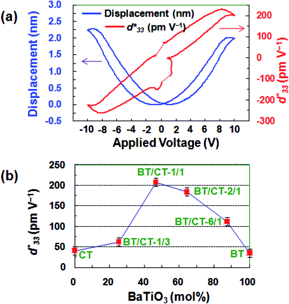 | ||
Fig. 6 (a) Displacement–voltage curve and calculated converse piezoelectric coefficient curve of mesocrystalline BT/CT mesocrystal (BT/CT-1/1) obtained by solvothermal treatment of BT/HT nanocomposite and Ca(OH)2 in water–ethanol mixed solvent. (b) Variations of converse piezoelectric coefficients ( ) of mesocrystalline BT/CT nanocomposites with different compositions, CT mesocrystals, and BT mesocrystals. ) of mesocrystalline BT/CT nanocomposites with different compositions, CT mesocrystals, and BT mesocrystals. | ||
The BT/CT-1/1 nanocomposite exhibits the specific advantage on the piezoelectric responses, which is higher than that of mesocrystalline BT/ST nanocomposites before annealing treatment.23 It may be owing to the difference of the incipient ferroelectric orthorhombic CT and the quantum paraelectric cubic ST.33 The piezoelectric results suggest that the BT/CT nanocomposites can achieve a high piezoelectric response due to the lattice strain at BT/CT heteroepitaxial interface. The highest piezoelectric response of BT/CT-1/1 with the composition close to BT/CT = 1/1 is due to the lattice strain derived from its heteroepitaxial interfaces with the highest density in the nanocomposite.
4 Conclusions
The novel 2D nanocrystal-aligned mesocrystalline BT/CT nanocomposites with controllable compositions were successfully synthesized by using a two-step solvothermal soft chemical process for the first time. These nanocomposites are polycrystals constructed from well-aligned BT and CT nanocrystals. There is a definite crystallographic topological relationship between the crystal-axis directions of the oriented BT and CT nanocrystals. All BT and CT nanocrystals in a platelike BT/CT nanocomposite particle show the same direction orientation, respectively, which gives two sets of single-crystal-like electron diffraction spots patterns. The mesocrystalline nanocomposites were formed via an in situ topochemical mesocrystal conversion mechanism. The BT/CT nanocomposite shows an average piezoelectric coefficient of 208 pm V−1 which is five times larger than that of BT mesocrystal. The BT/CT nanocomposites have high-density BT/CT heteroepitaxial nanostructure which exhibits the specific enhancement of piezoelectric response due to introduction of lattice strain at the interface.
Conflict of interest
The authors declare no competing financial interest.Acknowledgements
This work was supported in part by Grants-in-Aid for Scientific Research (B) (No. 26289240) from Japan Society for the Promotion of Science. This work was also supported in part by the National Natural Science Foundations of China (No. 21005003, No. 21501007, and No. 1502163), the Industrial Science and Technology Plan in Shaanxi Province of China (No. 2016GY-229), the Natural Science Foundation of Shaanxi Provincial Department of Education (16JF001), the Doctoral Scientific Research Starting Foundation of Baoji University of Arts and Science (No. ZK15050), and the Scientific and technological research and Development Plan in Baoji City of China (No. 15RKX-1-5-1).Notes and references
- H. N. Lee, H. M. Christen, M. F. Chisholm, C. M. Rouleau and D. H. Lowndes, Nature, 2005, 433, 395–399 CrossRef CAS PubMed.
- J. C. Agar, R. V. K. Mangalam, A. R. Damodaran, G. Velarde, J. Karthik, M. B. Okatan, Z. H. Chen, S. Jesse, N. Balke, S. V. Kalinin and L. W. Martin, Adv. Mater. Interfaces, 2014, 1, 1400098 CrossRef.
- J. Zhang, Z. L. Yang, F. Z. Lv, C. X. Gao and D. S. Xue, RSC Adv., 2014, 4, 61046–61050 RSC.
- W. Sun, Q. Yu, J. Y. Li and J.-F. Li, J. Phys. Chem. C, 2015, 119, 19891–19896 CAS.
- P. Zerrer, H. Wang, H. Yang, J. Yoon, A. Fouchet, R. Yu, M. G. Blamire and Q. X. Jia, Nat. Mater., 2008, 7, 314–320 CrossRef PubMed.
- S. A. Harrington, J. Zhai, S. Denev, V. Gopalan, H. Wang and Z. Bi, Nat. Nanotechnol., 2011, 6, 491–495 CrossRef CAS PubMed.
- E. Benckiser, M. W. Haverkort, S. Brück, E. Goering, S. Macke, A. Frañó, X. Yang, O. K. Andersen, G. Cristiani, H. U. Habermeier, A. V. Boris, I. Zegkinoglou, P. Wochner, H. J. Kim, V. Hinkov and B. Keimer, Nat. Mater., 2011, 10, 189–193 CrossRef CAS PubMed.
- Y. Zhang, C. H. Liu, J. B. Liu, J. Xiong, J. Y. Liu, K. Zhang, Y. D. Liu, M. Z. Peng, A. F. Yu, A. H. Zhang, Y. Zhang, Z. W. Wang, J. Y. Zhai and Z. L. Wang, ACS Appl. Mater. Interfaces, 2016, 8, 1381–1387 CAS.
- K. Kathan-Galipeau, P. P. Wu, Y. L. Li, L.-Q. Chen, A. Soukiassian, X. X. Xi, D. G. Schlom and D. A. Bonnell, ACS Nano, 2011, 5, 640–646 CrossRef CAS PubMed.
- A. P. Levanyuk and I. B. Misirlioglu, Appl. Phys. Lett., 2013, 103, 192906 CrossRef.
- N. Suzuki, M. B. Zakaria, N. L. Torad, K. C.-W. Wu, Y. Nemoto, M. Imura, M. Osada and Y. Yamauchi, Chem.–Eur. J., 2013, 19, 4446–4450 CrossRef CAS PubMed.
- D. Kar and D. Das, RSC Adv., 2015, 5, 61118–61126 RSC.
- H. Cölfen and M. Antonietti, Angew. Chem., Int. Ed., 2005, 44, 5576–5591 CrossRef PubMed.
- V. Kalyani, B. S. Vasile, A. Ianculescu, M. T. Buscaglia, V. Buscaglia and P. NanniCryst, Cryst. Growth Des., 2012, 12, 4450–4456 CAS.
- D. V. Talapin, J.-S. Lee, M. V. Kovalenko and E. V. Shevchenko, Chem. Rev., 2010, 110, 389–458 CrossRef CAS PubMed.
- T. H. Han, H. G. Wang and X. M. Zheng, RSC Adv., 2016, 6, 7829–7837 RSC.
- R. Q. Song and H. Cölfen, Adv. Mater., 2010, 12, 1301–1330 CrossRef PubMed.
- Q. Feng, M. Hirasawa and K. Yanagisawa, Chem. Mater., 2001, 13, 290–296 CrossRef CAS.
- X. G. Kong, D. W. Hu, Y. Ishikawa, Y. Tanaka and Q. Feng, Chem. Mater., 2011, 23, 3978–3986 CrossRef CAS.
- X. G. Kong, Y. Ishikawa, K. Shinagawa and Q. Feng, J. Am. Ceram. Soc., 2011, 94, 3716–3721 CrossRef CAS.
- D. W. Hu, X. G. Kong, K. Mori, Y. Tanaka, K. Shinagawa and Q. Feng, Inorg. Chem., 2013, 52, 10542–10551 CrossRef CAS PubMed.
- D. W. Hu, X. Luo, X. G. Kong, Y. Wang, Y. Tanaka and Q. Feng, CrystEngComm, 2015, 17, 1758–1764 RSC.
- D. W. Hu, H. Ma, Y. Tanaka, L. F. Zhao and Q. Feng, Chem. Mater., 2015, 27, 4983–4994 CrossRef CAS.
- D. W. Hu, W. X. Zhang, Y. Tanaka, N. Kusunose, Y. G. Peng and Q. Feng, Cryst. Growth Des., 2015, 15, 1214–1225 CAS.
- J. V. Lauritsen, S. Porsgaard, M. K. Rasmussen, M. C. R. Jensen, R. Bechstein, K. Meinander, B. S. Clausen, S. Helveg, R. Wahl and G. Kresse, ACS Nano, 2011, 7, 5987–5994 CrossRef PubMed.
- L.-Q. Cheng, K. Wang and J.-F. Li, Chem. Commun., 2013, 49, 4003–4005 RSC.
- P. Pinceloup, C. Courtois, A. Leriche and B. Thierry, J. Am. Ceram. Soc., 1999, 82, 3049–3056 CrossRef CAS.
- K. Yasui and K. Kato, J. Phys. Chem. C, 2015, 119, 24597–24605 CAS.
- Z. Deng, Y. Dai, W. Chen, X. M. Pei and J. H. Liao, Nanoscale Res. Lett., 2010, 5, 1217–1221 CrossRef CAS PubMed.
- T. Y. Ke, H. A. Chen, H. S. Sheu, J. W. Yeh, H. N. Lin, C. Y. Lee and H. T. Chiu, J. Phys. Chem. C, 2008, 112, 8827–8831 CAS.
- S. Y. Xu and J.-F. Li, J. Am. Ceram. Soc., 2011, 94, 3812–3818 CrossRef CAS.
- M. B. Ghasemian, Q. R. Lin, E. Adabifiroozjaei, F. F. Wang, D. W. Chu and D. Y. Wang, RSC Adv., 2017, 7, 15020–15026 RSC.
- W. Kinasea and K. Harad, Ferroelectrics, 2003, 283, 39–47 CrossRef.
Footnote |
| † Electronic supplementary information (ESI) available: Detailed experimental strategy, powder XRD patterns, SEM images, EDS-mapping TEM images, piezoelectric response of some materials reported, and Table S1 listing the atom mole ratios of Ti/Ba/Ca from corresponding EDS spectra. See DOI: 10.1039/c7ra03828c |
| This journal is © The Royal Society of Chemistry 2017 |