
 Open Access Article
 This Open Access Article is licensed under a Creative Commons Attribution-Non Commercial 3.0 Unported Licence
Effect of an improved gas diffusion cathode on carbamazepine removal using the electro-Fenton process
Wei Wang,
Yaobin Lu,
Haiping Luo,
Guangli Liu * and
Renduo Zhang
* and
Renduo Zhang
Guangdong Provincial Key Laboratory of Environmental Pollution Control and Remediation Technology, School of Environmental Science and Engineering, Sun Yat-sen University, Guangzhou 510275, China. E-mail: liugl@mail.sysu.edu.cn
First published on 12th May 2017
Abstract
The aim of this study was to investigate the effect of the diffusion layer of a gas diffusion cathode (GDC) on H2O2 production to enhance carbamazepine removal using the electro-Fenton process. The diffusion layer was made by carbon black and polytetrafluoroethylene with sodium sulfate (Na2SO4) as a pore former. Different ratios of Na2SO4 to carbon black (w/w) (i.e., 0%, 50%, 100%, 150%, and 200%) in the diffusion layer were tested. With an increase of the ratio, the average pore size in the diffusion layer and the electro-activity in the GDC increased simultaneously, which resulted in a higher mass transfer coefficient of oxygen and H2O2 production. In an undivided cell with platinum as the anode and 5.0 g L−1 Na2SO4 as the electrolyte, a maximum H2O2 concentration of 630 mg L−1 was achieved within 120 min in the GDC with the ratio of 150%. With an initial carbamazepine concentration of 50 mg L−1 and a current density of 5.0 mA cm−2, the maximum carbamazepine removal efficiency and rate reached 71% and 35.5 mg L−1 h−1, respectively. The removal rates in this study were much higher than those in the literature (35.5 vs. 0.03–10.0 mg L−1 h−1), mainly attributable to the diffusion layer modified by the pore former, which accelerated oxygen transfer and boosted H2O2 production. The results from this study should be useful to remove carbamazepine from wastewater treatment using the electro-Fenton (EF) process with improvement of pore structure in the diffusion layer of GDC.
1. Introduction
As effective methods for recalcitrant organic pollutant degradation in wastewater treatment, advanced oxidation processes, such as photocatalytic oxidation, Fenton, and ozonation,1 have been applied. Highly reactive species such as hydroxyl radicals can be produced with strong oxidation capability to decompose many kinds of organic pollutants in the oxidation processes. The electro-Fenton (EF) process is a promising method to combine hydroxyl radicals produced in the Fenton reaction with electrochemistry.2 Compared with the conventional Fenton process, the advantages of the EF process are as follows. On-site production of H2O2 can eliminate the potential risk of transportation and storage for H2O2. The Fenton reaction can be automatically controlled and easily maintained. The Fe2+ catalyst can be regenerated at the anode (Fe3+ + e− → Fe2+) and excess sludge can be minimized.3,4 Degradation of many refractory organic pollutants, such as phenol,5 4-chlorophenol,6 and perfluorooctanoate,7 has been examined using the EF process. However, one of key limitations of EF applications is the low concentration of oxygen dissolved in the solution according to the production reaction of hydrogen peroxide (O2 + 2e− + 2H+ → H2O2).4,8Usage of the gas diffusion cathode (GDC) is a promising way to accelerate oxygen diffusion and H2O2 production.4,8 The GDC is usually composed of three layers, that is, a diffusion layer, a current collector layer, and a catalyst layer.9 Because of high specific surface area and porosity of the diffusion layer, oxygen gas can efficiently pass through the diffusion layer and reach the interface between the catalyst layer and electrolyte, resulting in low energy consumption and high production of H2O2. Therefore, the pore structure of the diffusion layer plays an important role in oxygen transfer, which has been studied for the fuel cells.4,9 Because of low costs, carbon black and polytetrafluoroethylene (PTFE) have been commonly used as the raw materials to make the diffusion layer.4 PTFE is used the binder of carbon black to form many pores as gas channels.8 Carbon- and PTEF-based GDC has been applied to remove refractory organics from solutions in the EF process.5,10
As one of typical pharmaceuticals and personal care products, carbamazepine (CBZ) has been widely used.11 The total consumption of CBZ is about 1014 t in the world each year, which accounted for 96% of the total pharmaceutical consumption in 2007.12 However, overdose and metabolites of CBZ may result in damage of human's liver and emopoietic systems.13 CBZ has an amide structure that is stable and difficult to be degraded. The benzene ring of CBZ is a closed conjugate system and form π bond, resulting in high stability of CBZ.14 Moreover, the Henry coefficient of CBZ is as low as 1.09 × 10⁻⁵ Pa m3 mol−1 so that CBZ cannot be efficiently removed by the physical methods, such as air stripping treatment.15,16 The EF process has been utilized to degrade CBZ.17,18 Komtchou et al.17 demonstrated that 66% of 12 mg L−1 CBZ was removed within 120 min in the EF process under a current density of 1.8 mA cm−2 (0.2 A). A new material of carbon fiber coupled with cobalt phthalocyanine has been used as the cathode in the EF process, resulting in 97% of CBZ removal within 120 min.17 However, CBZ removal rates in the EF process are still low. For example, a CBZ removal rate of 4.0 mg L−1 h−1 with the EF process has been reported,17 which is only 40% of that in the Fenton-like process.19 To enhance the EF process, several strategies have been developed, including new catalysts, new configuration, etc.6,20,21 Nevertheless, the idea using the diffusion layer morphology to enhance the EF process on the recalcitrant organic pollutant removal has not been examined as far as we know.
The objective of this study was to investigate the effect of improved pore structure in the diffusion layer on H2O2 production to enhance CBZ degradation using the EF process. Different morphology and porosities of the diffusion layer with sodium sulfate (Na2SO4) as the pore former were characterized. Production of H2O2 and CBZ degradation in the EF process were determined. The mechanism of the effect of diffusion layer on the CBZ degradation was discussed.
2. Experiment
2.1 GDC preparation
The diffusion layer was prepared with Na2SO4 as the pore former as follows.8,22 Carbon black (EC-300J, Ketjenblack, Japan) of 1200 mg was mixed with each of different Na2SO4 dosages to obtain mass ratios of Na2SO4 to carbon black of 0%, 50%, 100%, 150%, and 200%. Each mixture was added with 30 mL of ethyl alcohol and stirred with ultrasonic treatment for 30 min. A PTFE emulsion (60 wt%, Hesen electric Co. Ltd., Shanghai, China) of 2800 mg was then added slowly into the mixture with agitation and ultrasonic treatment for 30 min. After excess alcohol evaporated at room temperature, the final mixture with dough-like was rolled on the stainless steel mesh (90 meshes, length × width × thickness = 8 cm × 4 cm × 0.2 mm) and formed 0.8 mm thickness of diffusion layer. The catalyst layer in the GDC was prepared as the same as the diffusion layer, except with a mass ratio 3![[thin space (1/6-em)]](https://www.rsc.org/images/entities/char_2009.gif) :1 of carbon black to PTFE without Na2SO4 addition. The catalyst layer was formed by rolling on another side of the stainless steel mesh. The GDC was boiled in the deionized water for 10 min and repeated for three times to remove Na2SO4 in the diffusion layer. Finally, the GDC was dried at 105 °C for 12 h. A GDC without Na2SO4 addition was sintered at 450 °C for 30 min and taken as the control. The total thickness of GDC was about 1 mm.
:1 of carbon black to PTFE without Na2SO4 addition. The catalyst layer was formed by rolling on another side of the stainless steel mesh. The GDC was boiled in the deionized water for 10 min and repeated for three times to remove Na2SO4 in the diffusion layer. Finally, the GDC was dried at 105 °C for 12 h. A GDC without Na2SO4 addition was sintered at 450 °C for 30 min and taken as the control. The total thickness of GDC was about 1 mm.
2.2 Reactor setup and operation
Undivided reactor was constructed with a cube plexiglass (4 cm × 4 cm × 4 cm). A hole in diameter of 3 cm was made in the cube plexiglass with an effective volume of 28 mL (diameter × length = 3 cm × 4 cm). The GDC had an effective area of 7 cm2 with a diameter of 3.0 cm. The distance between the anode and cathode was 4 cm. The length and diameter of the Pt anode were 3.3 cm and 0.5 mm, respectively. A Na2SO4 solution of 5 g L−1 as the supporting electrolyte and a current density of 50.0 A m−2 were used throughout all the tests. A solution of 50 mg L−1 CBZ was used in the undivided reactor for the experiments.2.3 Measurements and calculations
The diffusion layer morphology was observed using a Field Emission Scanning Electron Microscope (FESEM, JSM-6330F, Electron Corp., Japan). Porosities of the diffusion layer on the stainless steel meshes were determined using an automatic specific surface area and porosity analyzer (ASAP, 2020 (M), Micromeritics Corp., USA). Pore structures and distributions in the diffusion layers were determined using the N2 sorption–desorption method.Oxygen transfer in the diffusion layer was measured in a sealed glass bottle with 100 mL of 5 g L−1 Na2SO4 solution. The diffusion layer with an effective surface area of 7 cm2 was installed at one side of the glass bottle as the separator between the Na2SO4 solution inside and the air outside. Before the tests, the Na2SO4 solution was aerated by pure N2 at least 15 min to keep the dissolved oxygen concentration <1 mg L−1. Then dissolved oxygen concentrations in the Na2SO4 solution were recorded with a dissolved oxygen meter (YSI 550A, Xylem Inc., USA). The mass transfer coefficient of oxygen was calculated as follows:23,24
 | (1) |
The H2O2 concentration was determined by the colorimetric standard method.25 The CBZ concentration was determined with a high pressure liquid chromatograph (HPLC, P230II, Dalian Yilite analytic Instrument Co. Ltd., China). The mobile phase was the acetonitrile solution (50%, v/v). The CBZ removal efficiency was estimated by
 | (2) |
 | (3) |
3. Results and discussions
3.1 Characterization of gas diffusion layer in the cathode
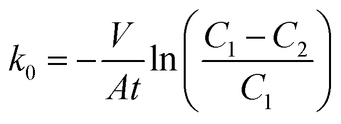
The SEM images on the surface morphology of diffusion layers using different Na2SO4 dosages as pore former are shown in Fig. 1. With increase of the ratios of Na2SO4 to carbon black from 0% to 200%, the surface morphology in the diffusion layers became coarser and more porous. As shown in Fig. 2, the ranges of pore sizes from 4 to 80 nm were similar among the different diffusion layers. However, the proportions of larger pores (>20 nm) were greater in the diffusion layers with higher amount of Na2SO4. The characteristics of the diffusion layers with the different ratios of Na2SO4 to carbon black are listed in Table 1. Average pore sizes in the diffusion layers with the different ratios of Na2SO4 to carbon black were in the order of 19.3 nm (200%) > 18.7 nm (150%) > 18.1 nm (100%) > 17.5 nm (50%) > 17.1 nm (CK) > 16.6 nm (0%). Total porosities in the different diffusion layers changed from 10.1% to 29.1% with increase of the ratios. The result of increase of pore sizes and porosities in the diffusion layers with the Na2SO4 amount was consistent with those reported in the polymer electrolyte fuel cells (PEFCs).26,27 Pores in the diffusion layers of the fuel cell could be increased by adding 20% (wt%) ammonium slat as pore former.26 With increase of sucrose dosages from 25 to 75 (w/o) as pore former in the diffusion layer of the fuel cell, the porosity of diffusion layer increased from 36% to 50%.27 | ||
| Fig. 1 SEM images on morphology of the diffusion layer for (A) the control check, and with ratios of Na2SO4 to carbon black of (B) 0%, (C) 50%, (D) 100%, (E) 150%, and (F) 200%. | ||
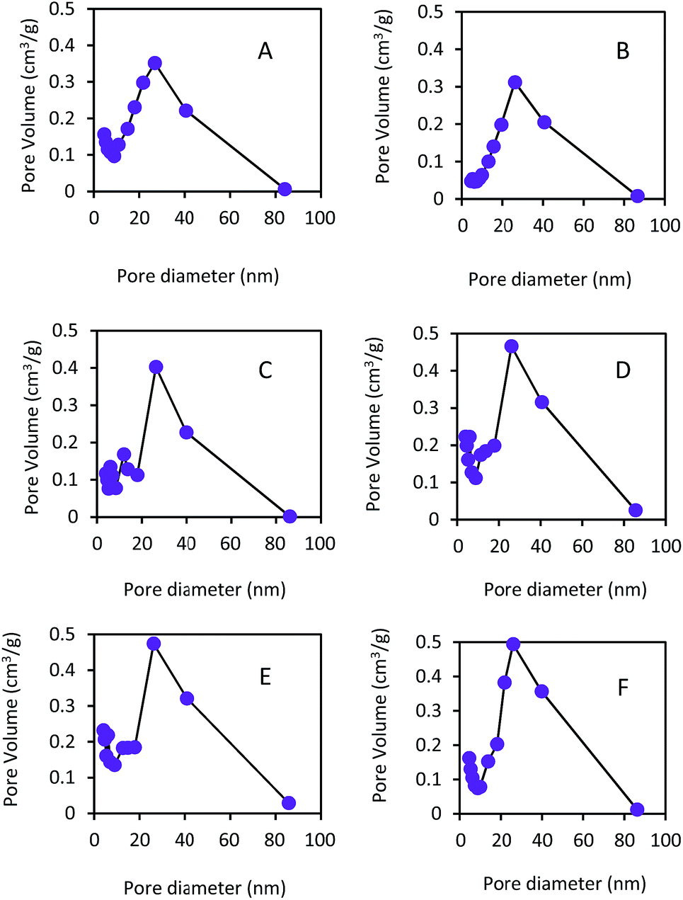 | ||
| Fig. 2 The pore size distributions of the diffusion layer with different content of pore former for (A) the control, and with ratios of Na2SO4 to carbon black of (B) 0%, (C) 50%, (D) 100%, (E) 150%, and (F) 200%. | ||
| Ratio of Na2SO4 to carbon black | Total porosity (%) | Average pore size (nm) |
|---|---|---|
| 0% | 10.1 | 16.6 |
| 50% | 20.2 | 17.5 |
| 100% | 24.1 | 18.1 |
| 150% | 27.3 | 18.7 |
| 200% | 29.1 | 19.3 |
| Control check | 15.3 | 17.1 |
The k0 values increased with the ratios of Na2SO4 to carbon black, that is, 19.1 × 10⁻⁴ cm s−1 (200%) > 18.0 × 10⁻⁴ cm s−1 (150%) > 17.2 × 10⁻⁴ cm s−1 (100%) > 17.0 × 10⁻⁴ cm s−1 (50%) > 15.8 × 10⁻⁴ cm s−1 (CK) > 15.2 × 10⁻⁴ cm s−1 (0%). The k0 values were linearly correlated to the porosities (with a correlation coefficient R = 0.973), indicating that the mass transfer capacity of oxygen was attributable to the porosity in the diffusion layers. However, a severely water leakage in the diffusion layer occurred when the ratio of Na2SO4 to carbon black increased to 300% (data not shown). To keep a stable H2O2 production, the maximum ratio of Na2SO4 to carbon black was kept at 200% (w/w) in the following tests. The k0 values in the diffusion layer was much higher than those in cation exchange membrane (0.94 × 10⁻⁴ cm s−1) and ultrafiltration membrane (0.19 × 10⁻⁴ cm s−1),23 suggesting that the diffusion layer made by carbon black had higher oxygen transfer capacity than those by other materials. The k0 values in this study were comparable to the mass transfer coefficient (27.0 × 10⁻⁴ cm s−1) in the electrochemical generation of H2O2.3 Moreover, the heat treatment (300–500 °C) of carbon black could increase carbon–oxygen surface groups on the carbon black particles and improve the lap shear strength of the adhesive joint between carbon black and adhesive.28
3.2 Performance of gas diffusion cathode
The linear sweep voltammetry measurements in different GDCs are shown in Fig. 3. With the different ratios of Na2SO4 to carbon black (w/w) in the diffusion layer, GDCs showed different oxidation and reduction activities with the same catalyst layers. At the potential of −2.0 V, the maximum current reached −0.171 A using the GDC with the ratio of 200%. GDCs with the ratios of 150% and 100% had almost the same current of −0.162 A. The maximum current of −0.117 A was obtained in the GDC with the ration of 0%. The result demonstrated that Na2SO4 as pore former could enhance the activity of GDC, which was consistent with those with other pore-forming agents, such as (NH4)2C2O4, NH4HCO3, NaCl, and PEG-200, reported in the literature.29 Large average pore sizes and high mass transfer coefficients in the diffusion layers could result in high oxidation–reduction activity of GDCs according to the diffusion layer characteristics mentioned above.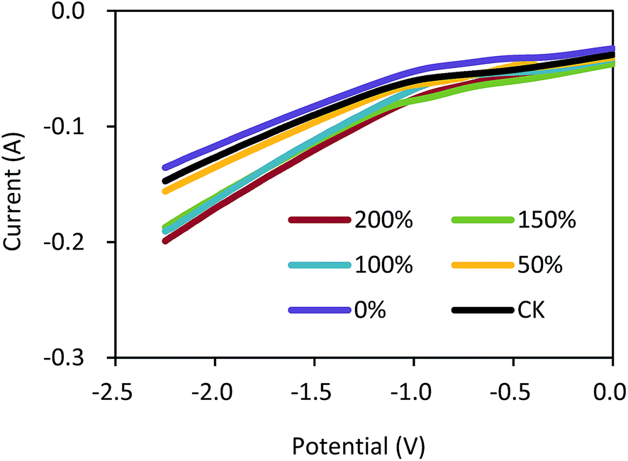 | ||
| Fig. 3 Linear sweep voltammetry measurement on the gas diffusion cathode with different ratios of Na2SO4 to carbon black. | ||
As shown in Fig. 4A, the H2O2 concentrations increased with the operation time under the current density of 5.0 mA cm−2. The GDCs with the ratios of 150% and 200% had almost the same H2O2 concentration of 630 mg L−1 within 120 min. The H2O2 concentrations were 427, 562, and 601 mg L−1 with the ratios of 0%, 50%, and 100% within 120 min, respectively. The CK had higher H2O2 concentration than that with 0% Na2SO4 within 120 min (550 vs. 427 mg L−1). The current efficiencies increased from 29% to 38% with the ratios from 0% to 50% within 120 min (Fig. 4B). However, the current efficiencies were not significantly improved and kept in a range of 38%–42% with the ratios from 50% to 200% within 120 min. The H2O2 concentrations and current efficiency in this study were comparable to those in other H2O2 electrochemical generation processes using GDCs.30,31 Nevertheless, our results demonstrated that the pore former could improve the H2O2 production in the electrochemical process, which should be important for the EF application in practice.
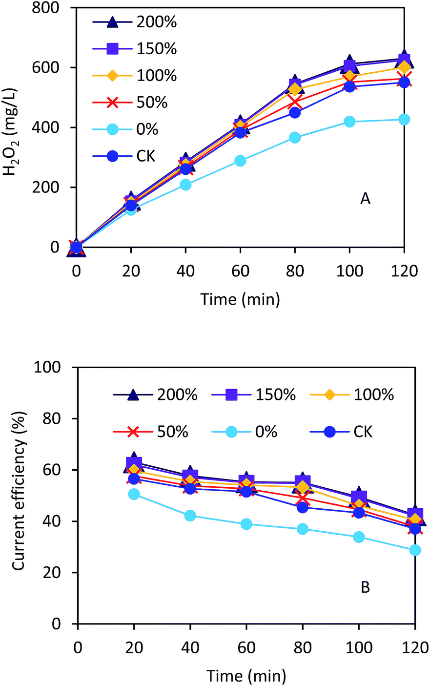 | ||
| Fig. 4 (A) H2O2 concentration and (B) current efficiency in the electrochemical cell using the gas diffusion cathode with different ratios of Na2SO4 to carbon black. | ||
3.3 CBZ degradation in the electro-Fenton with different GDCs
Under the condition of current density of 5.0 mA cm−2 and 4.56 g L−1 ferrous sulfate, the CBZ removal efficiencies increased with the running time in the EF process (Fig. 5A). The maximum CBZ removal efficiency reached 71% using the GDC with the ratio of Na2SO4 to carbon black of 150% within 60 min, which was much higher than that with 0% (44%) (Fig. 5B). The CBZ removal efficiencies were 62%, 67%, and 69% with the ratios of 50%, 100%, and 200%, respectively. The CBZ removal of the control (56%) was lower than that with the Na2SO4 addition, indicating that the pore former could enhance the EF process. The ratio of 200% resulted in lower CBZ removal than 150%, probably because of excess oxygen competition with CBZ during the EF process.32 Our results demonstrated that high concentration of CBZ (e.g. 50 mg L−1) could be efficiently removed in the EF process. A control test showed that the adsorption of CBZ on the GDC was 9.8 ± 0.5% within 60 min. Therefore, the CBZ removal in the EF process was mainly attributed to the oxidation by hydroxyl radicals.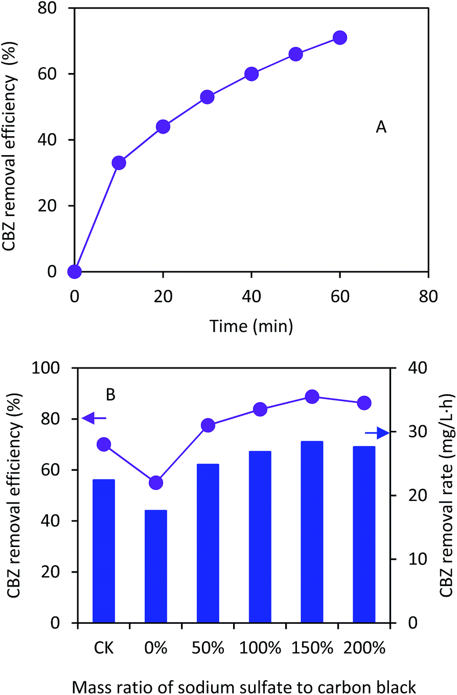 | ||
| Fig. 5 (A) CBZ removal change with time in the electrochemical cell using the gas diffusion cathode with the Na2SO4 to carbon black ratio of 150% (w/w); (B) change with ratios of Na2SO4 to carbon black within 60 min (initial conditions: 4.56 g L−1 FeSO4, 50 mg L−1 CBZ; operation conditions: pH = 3.0 and 5.0 mA cm−2 current density). | ||
Table 2 compares the CBZ removal results based on the Fenton, electro-Fenton and Fenton-like processes. While the CBZ removal efficiencies with the different processes were comparable, the CBZ removal rates in this study were much higher than those in the literature.17–19,33,34 The highest CBZ removal rate reached 35.5 mg L−1 h−1 using the GDC, which was about five and nine times higher than those using the Fenton-like process with the initial CBZ concentration of 15 mg L−1 and 100 mM H2O2 (7.5 mg L−1 h−1)34 and the electro-Fenton process (4.0 mg L−1 h−1),17 respectively. Full dosage of H2O2 was added at the beginning of the Fenton or Fenton-like process.19,33,34 The CBZ removal could take several hours via the Fenton or Fenton-like process, indicating that H2O2 was consumed gradually. However, residual H2O2 could compete with CBZ for exhausting the hydroxyl radical (eqn (4))35 and hinder high CBZ removal rate:
| H2O2 + ˙OH → HO2˙ + H2O | (4) |
| Methods | Initial concentration of CBZ (mg L−1) | Cathode catalyst | Current density (mA cm−2) | Reaction time (min) | Removal (%) | Removal rate (mg L−1 h−1) | Ref. |
|---|---|---|---|---|---|---|---|
| a CoPc-CF: carbon fiber coupled with cobalt phthalocyanine. | |||||||
| Fenton process | 0.1 | — | — | 180 | 84 | 0.03 | 33 |
| Fenton-like process | 15 | — | — | 120 | ∼100 | ∼7.5 | 34 |
| Fenton-like process | 10 | — | — | 60 | 100 | 10.0 | 19 |
| Electro-Fenton | 12 | Carbon felt cathode | 1.8 | 120 | 66 | 4.0 | 17 |
| 12 | 4.4 | 120 | 62 | 3.7 | |||
| 12 | 8.9 | 120 | 57 | 3.4 | |||
| 12 | 17.7 | 120 | 53 | 3.2 | |||
| Electro-Fenton | 5.9 | CoPc-CFa | — | 120 | 97 | 2.9 | 18 |
| Electro-Fenton (0% Na2SO4) | 50 | Carbon black with diffusion layer | 5.0 | 60 | 44 | 22.0 | This study |
| Electro-Fenton (50% Na2SO4) | 50 | 5.0 | 60 | 62 | 31.0 | ||
| Electro-Fenton (100% Na2SO4) | 50 | 5.0 | 60 | 67 | 33.5 | ||
| Electro-Fenton (150% Na2SO4) | 50 | 5.0 | 60 | 71 | 35.5 | ||
| Electro-Fenton (200% Na2SO4) | 50 | 5.0 | 60 | 69 | 34.5 | ||
In the electro-Fenton process with carbon felt or carbon fiber coupled with cobalt phthalocyanine (CoPc-CF) as cathode,17,18 without a diffusion layer in the cathode, the H2O2 concentration in the solution is usually pretty low. Fox example, the maximum H2O2 concentration was 1.44 mg L−1 after 120 min operation at the current density of 17.7 mA cm−2 (2.0 V) in the electro-Fenton with carbon felt cathode.17 Only 3.54 mg L−1 of the H2O2 concentration was produced after 30 min operation in the electro-Fenton with CoPc-CF cathode with an applied voltage of 2.5 V.18 However, because of high oxygen transfer coefficient in the diffusion layer of GDC, the H2O2 concentrations reached 150 mg L−1 within 20 min and 630 mg L−1 within 120 min operation in this study. The H2O2 concentrations gradually increased with the operation time, which reduced the chance of excess H2O2 accumulation and thus the reaction of eqn (4) might not occur. Therefore, high CBZ removal rate could be achieved in our electro-Fenton with GDC. Nevertheless, the CBZ removal varies with different conditions, including initial CBZ concentration, type of catalysts, current density, electrolytes, and others.17–19,33,34 It was difficult to make accurate comparison under the different conditions.
The GDC in the EF process is different from that in fuel cells, such as the proton exchange membrane fuel cell.26,29 Since the catalyst layer in the GDC in the EF process faces to aqueous solution, the diffusion layer in the EF should prevent the electrolyte leakage through the cathode.36,37 The specific requirement in the diffusion layer may limit the design of the pore structure of the diffusion layer using pore former, which should be further explored. Moreover, the life-time of the diffusion layer with pore former still needs to be investigated.
4. Conclusions
Different ratios of Na2SO4 to carbon black in the diffusion layer were investigated in the EF process for H2O2 production and CBZ removal. With increase of the ratios, the average pore size in the diffusion layer and the oxidation and reduction activity in the GDC increased simultaneously, resulting in high mass transfer coefficient of oxygen and H2O2 production. Under the current density of 5.0 mA cm−2, the maximum H2O2 concentration of 630 mg L−1 was achieved with the ratio of 150% within 120 min. With the initial CBZ concentration of 50 mg L−1 and 5.0 mA cm−2, the maximum CBZ removal efficiency and rate reached 71% and 35.5 mg L−1 h−1, respectively, using the GDC with the ratio of 150% within 60 min. Our experimental results demonstrated that the pore former can be used to optimize the pore structure of diffusion layer and to enhance the EF performance to CBZ removal in wastewater treatment.Acknowledgements
This work was partly supported by grants from the National Natural Science Foundation of China (No. 51278500, 41471181, and 51308557), the Natural Science Foundation of Guangdong Province (S2013010012984), the Science and Technology Program of Guangzhou (No. 201604010043), and the Fundamental Research Funds for the Central Universities (16lgjc65).References
- M. A. Oturan and J.-J. Aaron, Crit. Rev. Environ. Sci. Technol., 2014, 44, 2577–2641 CrossRef CAS.
- G. Ren, M. Zhou, M. Liu, L. Ma and H. Yang, Chem. Eng. J., 2016, 298, 55–67 CrossRef CAS.
- Z. Qiang, J.-H. Chang and C.-P. Huang, Water Res., 2002, 36, 85–94 CrossRef CAS PubMed.
- E. Brillas, I. Sirés and M. A. Oturan, Chem. Rev., 2009, 109, 6570–6631 CrossRef CAS PubMed.
- H. Luo, C. Li, C. Wu, W. Zheng and X. Dong, Electrochim. Acta, 2015, 186, 486–493 CrossRef CAS.
- G. Santana-Martínez, G. Roa-Morales, E. Martin del Campo, R. Romero, B. A. Frontana-Uribe and R. Natividad, Electrochim. Acta, 2016, 195, 246–256 CrossRef.
- Y. Liu, S. Chen, X. Quan, H. Yu, H. Zhao and Y. Zhang, Environ. Sci. Technol., 2015, 49, 13528–13533 CrossRef CAS PubMed.
- H. Luo, C. Li, C. Wu and X. Dong, RSC Adv., 2015, 5, 65227–65235 RSC.
- G. Inoue, K. Yokoyama, J. Ooyama, T. Terao, T. Tokunaga, N. Kubo and M. Kawase, J. Power Sources, 2016, 327, 610–621 CrossRef CAS.
- E. Brillas, J. C. Calpe and J. Casado, Water Res., 2000, 34, 2253–2262 CrossRef CAS.
- P. Braeutigam, M. Franke, R. J. Schneider, A. Lehmann, A. Stolle and B. Ondruschka, Water Res., 2012, 46, 2469–2477 CrossRef CAS PubMed.
- D. P. Mohapatra, S. K. Brar, R. D. Tyagi, P. Picard and R. Y. Surampalli, Talanta, 2012, 99, 247–255 CrossRef CAS PubMed.
- Y. Liu, S. Mei, D. Iya-Sou, S. Cavadias and S. Ognier, Chem. Eng. Process., 2012, 56, 10–18 CrossRef CAS.
- M. Suhasini, E. Sailatha, S. Gunasekaran and G. R. Ramkumaar, Spectrochim. Acta, Part A, 2015, 141, 252–262 CrossRef CAS PubMed.
- J. Sipma, B. Osuna, N. Collado, H. Monclús, G. Ferrero, J. Comas and I. Rodriguez-Roda, Desalination, 2010, 250, 653–659 CrossRef CAS.
- Y. Zhang, S.-U. Geißen and C. Gal, Chemosphere, 2008, 73, 1151–1161 CrossRef CAS PubMed.
- S. Komtchou, A. Dirany, P. Drogui and A. Bermond, Environ. Sci. Pollut. Res., 2015, 22, 11513–11525 CrossRef CAS PubMed.
- M. Liu, H. Xia, W. Lu, T. Xu, Z. Zhu and W. Chen, J. Appl. Electrochem., 2016, 1–10 CrossRef.
- V. M. Monsalvo, J. Lopez, M. Munoz, Z. M. D. Pedro, J. A. Casas, A. F. Mohedano and J. J. Rodriguez, Chem. Eng. J., 2015, 264, 856–862 CrossRef CAS.
- N. Li, J. An, L. Zhou, T. Li, J. Li, C. Feng and X. Wang, J. Power Sources, 2016, 306, 495–502 CrossRef CAS.
- J. F. Pérez, J. Llanos, C. Sáez, C. López, P. Cañizares and M. A. Rodrigo, Electrochem. Commun., 2016, 71, 65–68 CrossRef.
- H. Tang, S. Wang, M. Pan and R. Yuan, J. Power Sources, 2007, 166, 41–46 CrossRef CAS.
- J. R. Kim, S. Cheng, S.-E. Oh and B. E. Logan, Environ. Sci. Technol., 2007, 41, 1004–1009 CrossRef CAS PubMed.
- X. Y. Zhang, S. A. Cheng, X. Wang, X. Huang and B. E. Logan, Environ. Sci. Technol., 2009, 43, 8456–8461 CrossRef CAS PubMed.
- Standard Methods for the Examination of Water and Wastewater, ed. L. S. Clesceri, A. E. Greenberg and A. D. Eaton, American Public Health Association, Washington, DC, 20th edn, 1998 Search PubMed.
- J. H. Chun, K. T. Park, D. H. Jo, J. Y. Lee, S. G. Kim, E. S. Lee, J.-Y. Jyoung and S. H. Kim, Int. J. Hydrogen Energy, 2010, 35, 11148–11153 CrossRef CAS.
- G. Selvarani, A. K. Sahu, P. Sridhar, S. Pitchumani and A. K. Shukla, J. Appl. Electrochem., 2008, 38, 357–362 CrossRef CAS.
- S. W. Park and D. G. Lee, Composites, Part A, 2010, 41, 1597–1604 CrossRef.
- J. Liu, C. Yang, C. Liu, F. Wang and Y. Song, Ind. Eng. Chem. Res., 2014, 53, 5866–5872 CrossRef CAS.
- X. Yu, M. Zhou, G. Ren and L. Ma, Chem. Eng. J., 2015, 263, 92–100 CrossRef CAS.
- R. M. Reis, A. A. G. F. Beati, R. S. Rocha, M. H. M. T. Assumpção, M. C. Santos, R. Bertazzoli and M. R. V. Lanza, Ind. Eng. Chem. Res., 2012, 51, 649–654 CrossRef.
- L. Zhou, M. Zhou, C. Zhang, Y. Jiang, Z. Bi and J. Yang, Chem. Eng. J., 2013, 233, 185–192 CrossRef CAS.
- D. P. Mohapatra, S. K. Brar, R. D. Tyagi, P. Picard and R. Y. Surampalli, Sci. Total Environ., 2013, 447, 280–285 CrossRef CAS PubMed.
- S. P. Sun, Z. Xia, C. Li and A. T. Lemley, Chem. Eng. J., 2014, 244, 44–49 CrossRef CAS.
- H. Zhang, D. Zhang and J. Zhou, J. Hazard. Mater., 2006, 135, 106–111 CrossRef CAS PubMed.
- T. Harrington and D. Pletcher, J. Electrochem. Soc., 1999, 146, 2983–2989 CrossRef CAS.
- Y. Lei, H. Liu, Z. Shen and W. Wang, J. Hazard. Mater., 2013, 261, 570–576 CrossRef CAS PubMed.
| This journal is © The Royal Society of Chemistry 2017 |