
 Open Access Article
 This Open Access Article is licensed under a
 Creative Commons Attribution 3.0 Unported Licence
Improved rate capability of a LiNi1/3Co1/3Mn1/3O2/CNT/graphene hybrid material for Li-ion batteries
Xing Li *a,
Xing Zhaoa,
Ming-Shan Wanga,
Kang-Jia Zhanga,
Yun Huanga,
Mei-Zhen Qub,
Zuo-Long Yub,
Dong-sheng Geng*c,
Wen-gao Zhaod and
Jian-ming Zheng*d
*a,
Xing Zhaoa,
Ming-Shan Wanga,
Kang-Jia Zhanga,
Yun Huanga,
Mei-Zhen Qub,
Zuo-Long Yub,
Dong-sheng Geng*c,
Wen-gao Zhaod and
Jian-ming Zheng*d
aThe Center of New Energy Materials and Technology, School of Materials Science and Engineering, Southwest Petroleum University, Xindu Road 8, Chengdu 610500, China. E-mail: lixing@swpu.edu.cn; Fax: +86 28 83037409; Tel: +86 28 83037409
bChengdu Institute of Organic Chemistry, Chinese Academy of Science, Chengdu 610041, China
cCenter for Green Innovation, School of Mathematics and Physics, University of Science and Technology Beijing, Beijing, 100083, China. E-mail: dgeng@ustb.edu.cn
dEnergy and Environment Directorate, Pacific Northwest National Laboratory, 902 Battelle Boulevard, Richland, WA 99354, USA. E-mail: jianming.zheng@pnnl.gov
First published on 4th May 2017
Abstract
In this work, a LiNi1/3Co1/3Mn1/3O2/CNT/Graphene nanosheet (NCM/CNT/GN) hybrid material has been successfully prepared by a facile wet chemical method. The hierarchical structures of the CNT and GN are well maintained in the NCM/CNT/GN hybrid material, and their addition does not affect the layered crystal structure of the NCM. It is found that the NCM/CNT/GN hybrid material forms a three-dimensional (3D) spider-web like network structure via the interconnection of one-dimensional CNT and two-dimensional GN. As a result, the NCM/CNT/GN hybrid material exhibits the least electrode polarization, significantly enhanced rate capability with a high discharge capacity of 134 mA h g−1 at 3.0C, as well as excellent cycling performance. The improved electrochemical performances of NCM/CNT/GN hybrid material could be well correlated with the synergistic effects of CNT and GN, efficiently building the 3D conductive network, which largely enhances the electronic conductivity and the lithium ion diffusion in the NCM electrode.
Introduction
Lithium-ion batteries (LIBs) as important energy storage devices have been widely used in various electronic devices such as cellular phones, cameras, laptop computers, etc. In view of their high energy density and good cyclability, recently LIBs have also regarded as the preferred power sources for hybrid electric vehicle (HEV) or electric vehicle (EV).1–3 LiCoO2 is one of the most widely used cathode materials in commercial LIBs. However, its drawbacks of high cost, poor thermal stability, toxicity and a low practical specific capacity of 130–140 mA h g−1 have fundamentally limited its large-scale application in LIBs dedicated for HEV or EV.4 To enable vehicle electrification, there is an urgent demand for developing new generation of LIBs with high energy density, high power capability and long cycle life.5–7 An appropriate selection of the cathode material is one of the key factors in improving the energy density and other performances of LIBs. Recently, a series of layer structured metal oxides of LiNixCoyMnzO2 have been widely investigated due to their improved structural stability and electrochemical properties as compared to traditional LiCoO2,8–10 including LiNi1/3Co1/3Mn1/3O2, LiNi0.8Co0.1Mn0.1O2, LiNi0.5Co0.2Mn0.3O2. Among them, LiNi1/3Co1/3Mn1/3O2 has attracted much research attention as one of the mixed transition metal oxides because of its relatively low content of Co, high specific capacity and superior thermal stability.11However, the LiNi1/3Co1/3Mn1/3O2 still suffers from some technical challenges. The first one is the undesired interfacial reactions between LiNi1/3Co1/3Mn1/3O2 and electrolytes, which could be attributed to the catalytic effects of the redox couple of Co3+/4+ that is incurred when the LiNi1/3Co1/3Mn1/3O2 is being charged up to a high cut-off voltage of 4.55 V.12,13 The second one is the structure disruption and cation disorder between Li+ and Ni2+ in the LiNi1/3Co1/3Mn1/3O2 crystal lattice, which can reduce the specific capacity and deteriorate the cycling stability of LiNi1/3Co1/3Mn1/3O2.14 The third one is the relatively poor electronic conductivity of the LiNi1/3Co1/3Mn1/3O2 resulting in serious electrode polarization and poor rate capability, which limits the practical application of LiNi1/3Co1/3Mn1/3O2 as cathode in the power-type LIBs for HEV or EV.15 To prevent the interfacial side reactions, researchers have attempted to coat the LiNi1/3Co1/3Mn1/3O2 with chemically stable and electrochemically inert materials such as FePO4,16 Al2O3,17 AlPO4,18 etc. To decrease the cation disorder, some strategies such as Al partial substitution for Mn19 or Co;20 Fe partial substitution for Mn;21 F22 partial substitution for O anion, in the LiNi1/3Co1/3Mn1/3O2 crystal lattice, even Ti23 surface doping have been implemented.
As the poor electronic conductivity of LiNi1/3Co1/3Mn1/3O2 may considerably affects the electrode polarization and thus rate capability of LIBs, acetylene black is usually adopted as conductive additive to increase the electronic conductivity and therefore improve electrochemical performance of NCM cathodes, especially the rate capability.24,25 However, it is difficult to effectively establish an electrical percolation network due to the non-uniform dispersion of nano carbon particles in the mixing procedure.26,27 Owing to the high electronic conductivity, large specific surface area and excellent structural stability, carbon nanotube (CNT)28,29 and graphene nanosheet (GN)30 have been used as conductive nanostructured carbon matrices to improve the electronic conductivity, specific capacity, rate capability and cycling stability of the LiNi1/3Co1/3Mn1/3O2. However, both the CNT and GN are inclined to agglomerate because of the influence of van der Waals force and surface functional groups. Therefore, only CNTs or sole GNs might not be capable of efficiently building a conductive network in the electrode to improve the particle-to-particle electronic transfer of the active material. It is necessary to avoid the self-aggregation while constructing a three-dimensional carbon network by sufficiently utilizing the advantages of one-dimensional (1D) CNT and two-dimensional (2D) GN.
In the present study, we prepared a LiNi1/3Co1/3Mn1/3O2/CNT/GN (short as NCM/CNT/GN) hybrid material that possesses the conductive nanostructured carbon matrix composed of both CNT and GN. In the structure of hybrid material, the 2D graphene nanosheet covered on the surface of isolated NCM particles, while the 1D carbon nanotubes act as bridges to connect the NCM particles and the graphene nanosheets. This synergistic effect of 1D CNTs and 2D GNs efficiently built a three-dimensional (3D) conductive spider-web like framework in the electrode. Taking advantages of the 3D conductive carbon network, the materials exhibited lower electrode polarization, better rate capability and improved cycling stability than those of NCM/CNT or NCM/GN counterparts.
Experimental
Preparation of the layered metal oxide LiNi1/3Co1/3Mn1/3O2
The layered structure lithium metal oxide LiNi1/3Co1/3Mn1/3O2 (NCM) was synthesized by a facile wet chemical method. Firstly, the Ni(CH3COO)2·4H2O, Co(CH3COO)2·4H2O, and Mn(CH3COO)2·4H2O (mole ratio of Ni![[thin space (1/6-em)]](https://www.rsc.org/images/entities/char_2009.gif) :Co:Mn = 1:1:1) were dissolved in deionized water to form a stable solution. Then, the stoichiometric amount of Li2CO3 was slowly added into the above solution to form a uniform mixture. 6% excess of Li source was used to compensate the volatilization loss during calcination at high temperature. The mixture was heated at 373 K with magnetic stirring for 4 h to obtain a brown powder. Finally, the brown powders were calcined at 1073 K for 8 h in air atmosphere to obtain the product of LiNi1/3Co1/3Mn1/3O2.
:Co:Mn = 1:1:1) were dissolved in deionized water to form a stable solution. Then, the stoichiometric amount of Li2CO3 was slowly added into the above solution to form a uniform mixture. 6% excess of Li source was used to compensate the volatilization loss during calcination at high temperature. The mixture was heated at 373 K with magnetic stirring for 4 h to obtain a brown powder. Finally, the brown powders were calcined at 1073 K for 8 h in air atmosphere to obtain the product of LiNi1/3Co1/3Mn1/3O2.
Preparation of NCM/CNT/GN, NCM/CNT and NCM/GN hybrid materials
For preparation of the NCM/CNT/GN, first, 60 mg of CNT (hydroxyl multi-wall carbon nanotubes, >50 nm in diameter, 5–10 μm in length and >95 wt% in purity, Timesnano) and graphene nanosheet (less than 10 layers, 3–5 μm in diameter, >99 wt% in purity, Daying Juneng Co., Ltd) with a mass ratio of 1:2 was dispersed in 30 ml ethanol with ultrasonication to form a stable suspension. Then, 540 mg of LiNi1/3Co1/3Mn1/3O2 (weight ratio of LiNi1/3Co1/3Mn1/3O2 to (CNT + GN) was 90:10) was added into the above suspension. Finally, with vigorous magnetic stirring and heating at 353 K to evaporate the ethanol, the black LiNi1/3Co1/3Mn1/3O2/CNT/GN hybrid material with 10 wt% of CNT + GN conductive carbon framework was obtained. The LiNi1/3Co1/3Mn1/3O2/CNT and LiNi1/3Co1/3Mn1/3O2/GN hybrid materials were prepared in a similar manner. The percentage of the CNT or GN in the hybrid was controlled the same at 10 wt%. The LiNi1/3Co1/3Mn1/3O2/acetylene black (NCM/AB) hybrid material with 10 wt% AB was also prepared for comparison.
Materials characterization
The crystallographic information of the hybrid samples was characterized by X-ray powder diffraction (XRD, Xpert MPD DY1219) with a scan speed of 5° min−1 in the 2θ range of 10–90°. The morphology features of the as-prepared hybrid materials corresponding electrodes were scrutinized by scanning electron microscopy (SEM, FEI INSPECT-F). The Raman spectra of the hybrid materials were recorded on a Renishaw InVia using laser excitation wavelength of 785 nm.Electrochemical measurements
The cathode electrode was prepared by coating mixture slurries containing 95 wt% hybrid cathode material and 5 wt% LA-132 binder onto an aluminum foil. The weight of active material containing the conductive nanostructured carbon matrix in the working electrode was about 3.50 mg, and the geometric area of the electrode was 1.54 cm2. The specific capacity is calculated on the basis of NCM. In an Ar-filled glovebox, the cathode electrode was assembled into R2032 coin-type cell with Li metal as anode electrode and Celgard 2400 as separator. The electrolyte was 1 M LiPF6 in ethylene carbonate (EC), diethyl carbonate (DEC) and dimethyl carbonate (DMC) (EC:DEC:DMC volume ratio of 1:1:1). The electrochemical performance measurements of the hybrid cathodes were carried out on BTS-5V 20 mA cell testing instrument (NEWARE Electronic Co., Ltd) between cut-off voltages of 2.5–4.6 V (vs. Li/Li+) at different charge/discharge current rates at room temperature. The specific capacity of the hybrid cathode was calculated based on the mass of active LiNi1/3Co1/3Mn1/3O2. The electrochemical impedance spectroscopy (EIS) measurements were performed at charged state of 4.6 V using a CHI660D electrochemical workstation in the frequency range from 100 kHz to 0.01 Hz with a potential perturbation of 5 mV. The cyclic voltammogram (CV) of the hybrid material electrode was recorded between 2.5–4.6 V (vs. Li/Li+) with a scan rate of 0.1 mV s−1.
Results and discussion
The schematic illustration of the preparation process of the NCM/CNT/GN hybrid materials is shown in Fig. 1a. A facile wet chemical method is adopted to construct the 3D conductive nanostructured carbon framework composed of CNT, GN and NCM particles. An appropriate amount ethanol is added as dispersant. Then, the NCM, CNT, and GN are dispersed to form a uniform suspension with the help of ultrasonication. Through the wet chemical method, the NCM, CNT, and GN are homogeneously redistributed by the ethanol dispersant. During the drying process, the isolated materials of NCM, CNT, and GN become interconnected with each other due to the interactions between the NCM particle and the surface functional groups of CNT and GN. The graphene nanosheets are stretched by the NCM particles, and meanwhile the graphene nanosheets closely cover on the surface of NCM particles. Furthermore, the CNTs homogeneously distribute between the gaps of NCM particles and graphene nanosheets, which form a conducting bridge to facilitate the transfer of lithium ions and electrons. The preparation processes of the NCM/GN (Fig. 1b), NCM/CNT (Fig. 1c) and NCM/AB (Fig. 1d) hybrid materials are similar to that of NCM/CNT/GN hybrid material. However, compared with the structure of 3D NCM/CNT/GN, due to the high surface activity and large specific surface area of nano materials, single 0D AB, 1D CNT, or 2D GN as conductive additive all exist severe agglomeration and could not efficiently construct a conductive nanostructured carbon network.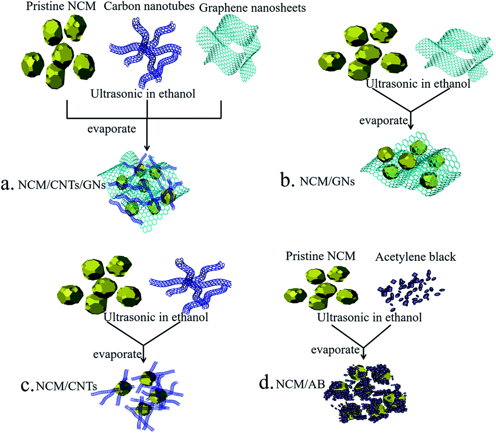 | ||
| Fig. 1 Schematic illustration of the preparation of NCM/CNT/GN (a), NCM/GN (b), NCM/CNT (c), and NCM/AB (d) hybrid materials. | ||
The XRD patterns of pristine NCM (e), NCM/ABs (d), NCM/CNTs (c), NCM/GNs (b) and NCM/CNT/GN (a) are presented in Fig. 2. It can be found that all samples exhibit similar XRD patterns which can be indexed to α-NaFeO2 type hexagonal structure with a space group R![[3 with combining macron]](https://www.rsc.org/images/entities/char_0033_0304.gif) m, with no extra impurity peaks being found. The splitting doublets of (006/012) and (108/110) at ca. 38° and ca. 65° are clearly identified, which indicates that NCM particles in all samples have a well-defined layered structural characteristics.31,32 The intensity ratio of (003)/(104) is determined to be about 1.331 for all samples, indicating a low Ni2+/Li+ cation mixing in the prepared NCM hybrid cathode material. The calculated lattice constants for NCM, NCM/CNT, NCM/AB, NCM/GN and NCM/CNT/GN are compared in Table 1, which are close to each other suggesting that the CNT + GN, GN, CNT or AB do not affect the layered crystal structure of active NCM.
m, with no extra impurity peaks being found. The splitting doublets of (006/012) and (108/110) at ca. 38° and ca. 65° are clearly identified, which indicates that NCM particles in all samples have a well-defined layered structural characteristics.31,32 The intensity ratio of (003)/(104) is determined to be about 1.331 for all samples, indicating a low Ni2+/Li+ cation mixing in the prepared NCM hybrid cathode material. The calculated lattice constants for NCM, NCM/CNT, NCM/AB, NCM/GN and NCM/CNT/GN are compared in Table 1, which are close to each other suggesting that the CNT + GN, GN, CNT or AB do not affect the layered crystal structure of active NCM.
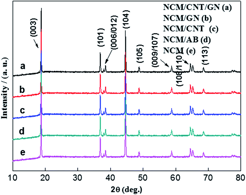 | ||
| Fig. 2 XRD patterns of the pristine NCM, NCM/AB, NCM/CNT, NCM/GN and NCM/CNT/GN composites. | ||
| Samples | a/Å | c/Å | I(003)/I(104) |
|---|---|---|---|
| NCM/CNT/GN | 2.851 | 14.299 | 1.333 |
| NCM/GN | 2.853 | 14.231 | 1.332 |
| NCM/CNT | 2.852 | 14.230 | 1.331 |
| NCM/AB | 2.850 | 14.232 | 1.331 |
| NCM | 2.853 | 14.231 | 1.332 |
Fig. 3 shows the Raman spectra of NCM/CNT/GN (a), NCM/GN (b), NCM/CNT (c), NCM/AB (d) and pristine NCM (e). It can be clearly observed that the pristine NCM powders displays only two bands of A1g and Eg at about 465 cm−1 and 585 cm−1 respectively. In the NCM layered structure, the M (transition metal)–O stretching and O–M–O bending of oxygen atom contribute to the A1g and Eg bands.33 Raman spectra of the NCM/CNT/GN, NCM/GN, NCM/CNT and NCM/AB hybrids show two additional bands at about 1306 and 1593 cm−1, which can be assigned to the D and G bands of graphene, carbon nanotube and acetylene black. The D bands reflect the defect or disorder in the carbon crystals, the G bands arise from the in-plane vibration of sp2 carbon atoms of graphene sheet.34,35 The NCM/CNT/GN and NCM/GN show strong 2D bands at about 2700 cm−1, which is the characteristic of graphene nanosheets.36,37 These results indicate that the structures of CNT + GN, GN, CNT or AB are maintained during the preparation of the hybrid materials.
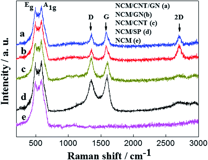 | ||
| Fig. 3 Raman spectra of the pristine NCM, NCM/AB, NCM/CNT, NCM/GN and NCM/CNT/GN hybrid materials. | ||
The SEM images of NCM/CNT/GN, NCM/GN, NCM/CNT, and NCM/AB electrodes at high magnifications are shown in Fig. 4. As shown in Fig. 4d and h, the NCM material shows polyhedral shape with average particle size ranging from 300 nm to 500 nm. Furthermore, it can be seen that the agglomerated AB barely piles on the surface of some NCM particles, and the most surface of NCM particles are exposed. On the one hand, the exposed surface would lead to the undesired interfacial reactions especially at high voltages. On the other hand, the agglomeration of AB particles also leads to the decrease of the electrical conductivity, which means that the electrochemical rate capability might be compromised. From Fig. 4c and g, as it can be seen, the CNTs are intertwined to form agglomerates that are randomly distributed on the NCM particles. At the same time, there still exists some uncoated surface of the NCM particles. The sample of NCM/GN in the Fig. 4b and f shows that the particles of NCM active material are homogeneously dispersed on the graphene nanosheets, and to some extent, some of graphene nanosheets act as a coating layer to cover and wrap the NCM particles. However, a large number of NCM particles do not directly connect with graphene layer and distributed in the empty space of graphene sheets. Compared with the NCM/CNT, NCM/GN and NCM/AB, the NCM/CNT/GN hybrid material shown in the Fig. 4a and e presents that graphene nanosheets homogeneously dispersed in the electrode, and most of the NCM particles are coated within the graphene nanosheets. Besides, carbon nanotubes are distributed on the graphene sheets and NCM particles, which function as a bridge to construct a 3D spider web like electronic conducting network. Such a unique network structure could largely improve the electronic conductivity of NCM electrode. In addition, it may also mitigate the interfacial reaction between active material and the electrolyte.
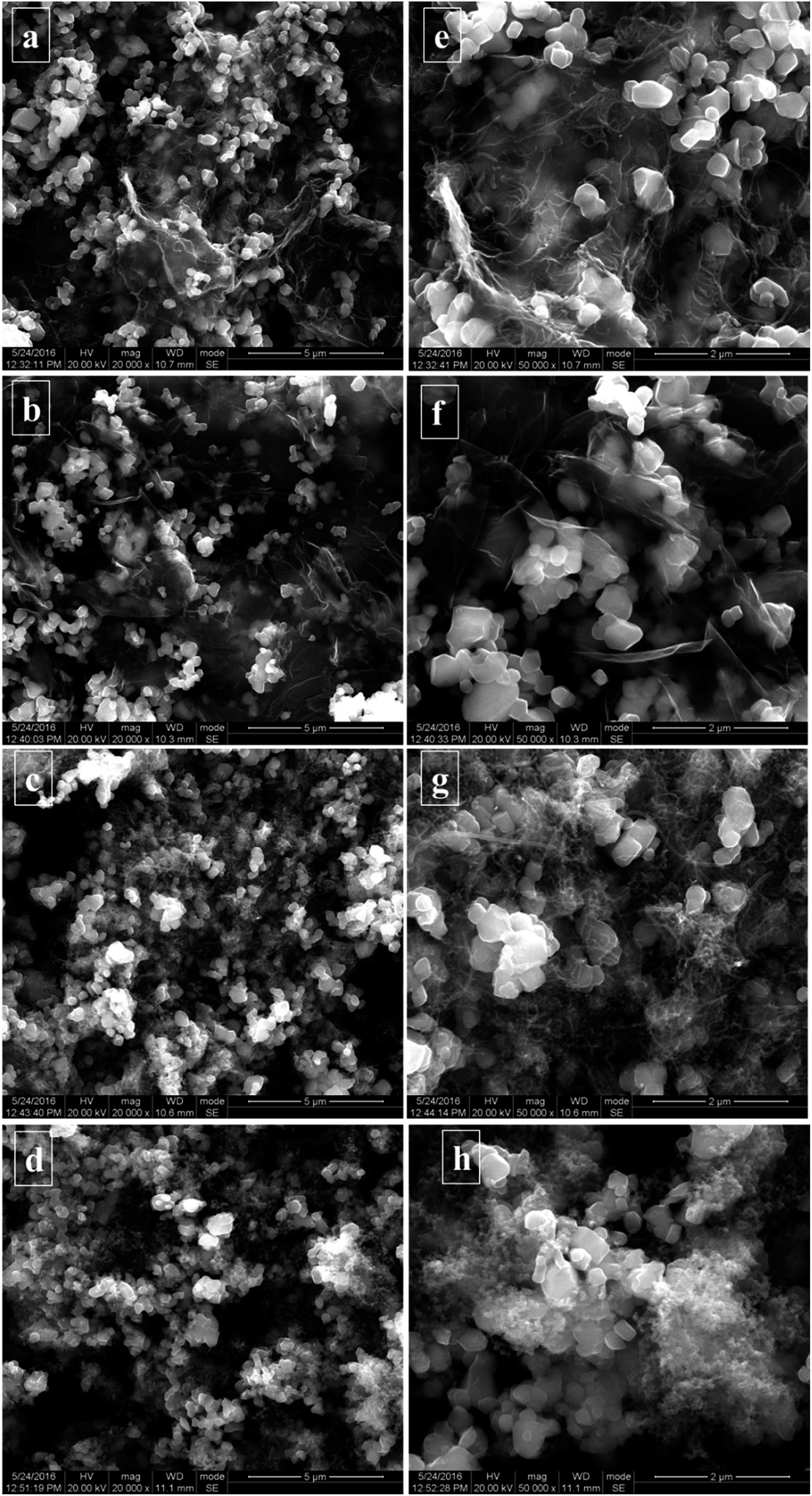 | ||
| Fig. 4 SEM images of NCM/CNT/GN (a and e), NCM/GN (b and f), NCM/CNT (c and g), and NCM/AB (d and h) electrodes. | ||
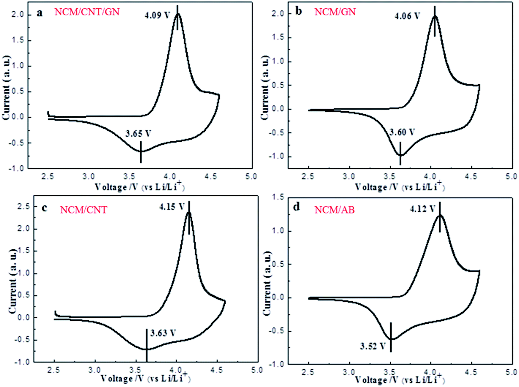
The CV curves for the NCM/CNT/GN (a), NCM/GN (b), NCM/CNT (c) and NCM/AB (d) hybrids recorded at a scan rate of 0.1 mV s−1 from 2.5 to 4.6 V are demonstrated in Fig. 5. The CV curves show a cathodic peak at about 3.6 V, and an anodic peak at about 4.1 V for all samples. No reduction peak appears at 3.2 V, which is the reduction of Mn4+, indicating that the Mn keeps the oxidation status of +4 in the hybrid material.38 The well-defined redox peaks indicating the reversible extraction and insertion of lithium ions out of/into the NCM crystal. And those redox peaks are corresponding to the Ni2+/Ni4+ and Co3+/4+ redox couples.39,40 As shown in Table 2, it can be observed that the NCM/CNT/GN hybrid material shows the smallest potential difference between the oxidation and reduction peaks among the samples, which confirms that the lowest electrode polarization can be achieved by the introduction of both GN and CNT. The enhanced electrochemical reaction kinetics could be ascribed to the efficient spider web like conducting network contributed by the synergistic effects of CNT and GN.
 | ||
| Fig. 5 CV curves of NCM/CNT/GN (a), NCM/GN (b), NCM/CNT (c) and NCM/AB (d) at a scan rate of 0.1 mV s−1 from 2.5 to 4.6 V. | ||
| Samples | Anodic peak (V) | Cathodic peak (V) | Potential difference (V) |
|---|---|---|---|
| NCM/CNT/GN | 4.09 | 3.65 | 0.44 |
| NCM/GN | 4.06 | 3.60 | 0.46 |
| NCM/CNT | 4.15 | 3.63 | 0.52 |
| NCM/AB | 4.12 | 3.52 | 0.60 |
Fig. 6 shows the specific discharge capacities of NCM/CNT/GN, NCM/GN, NCM/CNT and NCM/AB electrodes at various current rates. In the voltage range of 2.5–4.6 V (vs. Li/Li+), the NCM/CNT/GN, NCM/GN, NCM/CNT, and NCM/AB hybrid materials show the initial discharge capacities of 200 mA h g−1, 191 mA h g−1, 196 mA h g−1 and 209 mA h g−1 at 0.2C, respectively. Although NCM/CNT/GN hybrid material does not show obvious advantage in the discharge specific capacity at low current rate of 0.2C, it exhibits obviously higher discharge capacities upon increasing current rates, ranging from 0.5 to 3.0C, than those of NCM/GN, NCM/CNT or NCM/AB. The discharge capacities of NCM/CNT/GN at the rates of 0.5C, 1.0C, 2.0C and 3.0C are 187 mA h g−1, 175 mA h g−1, 156 mA h g−1 and 134 mA h g−1, respectively. Especially at high rate of 3.0C, the NCM/CNT/GN is still capable of delivering a high specific capacity of 134 mA h g−1, which is much higher than those of NCM/GN (87 mA h g−1), NCM/CNT (62 mA h g−1), and NCM/AB (51 mA h g−1). These could be closely correlated with the efficient increase of electronic conductivity in the presence of the 3D conductive network of CNT and GN, which alleviates the electrode polarization especially at high current rates. The improved rate capability of the NCM/CNT/GN also was reported by using zinc as anode in an neutral Li2SO4 solution.41
 | ||
| Fig. 6 Rate performances of the NCM/CNT/GN, NCM/GN, NCM/CNT and NCM/AB hybrids in the voltage range of 2.5–4.6 V. | ||
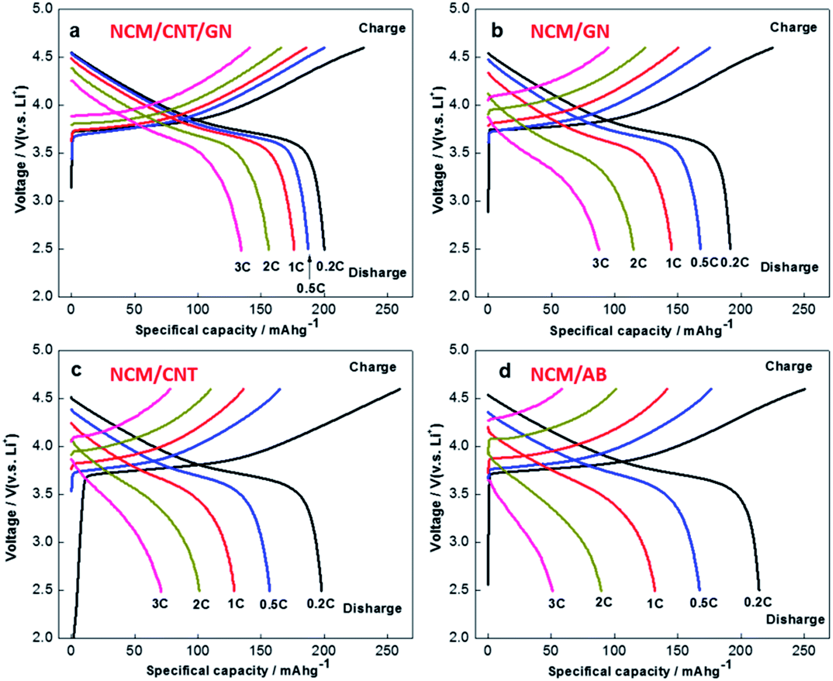
Fig. 7 further compares the charge and discharge curves of the NCM/CNT/GN, NCM/GN, NCM/CNT and NCM/AB hybrids. It can be observed that all the sample exhibit the similar voltage plateaus between 3.5–4.0 V. Obviously, the NCM/CNT/GN hybrid shows the least increase of electrode polarization with the rising of charge/discharge current densities, therefore, delivering higher charge and discharge specific capacities at different C rates than those of NCM/GN, NCM/CNT and NCM/AB.
 | ||
| Fig. 7 Charge and discharge curves of the NCM/CNT/GN, NCM/GN, NCM/CNT and NCM/AB hybrids. | ||
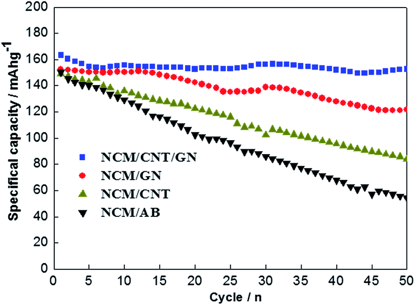
Fig. 8 shows the cycling performances of NCM/CNT/GN, NCM/GN, NCM/CNT and NCM/AB electrodes at the current rate of 1.0C between 2.5 and 4.6 V. The NCM/CNT/GN hybrid material presents an initial discharge capacity of 162 mA h g−1, and a discharge specific capacity of 152 mA h g−1 after 50 cycles, corresponding to a capacity retention of up to 93.8%. On the contrary, the NCM/GN, NCM/CNT and NCM/AB electrodes deliver initial discharge capacities of 152 mA h g−1, 150 mA h g−1, and 148 mA h g−1 at 1.0C, along with inferior capacity retention of 78.9%, 53.3% and 31.6%, respectively. Obviously, the NCM/CNT/GN electrode shows the best cycling performance among the samples, which should be attributed to the efficient increase of electronic conductivity in the presence of the 3D conductive network of CNT and GN. For the NCM/GN, NCM/CNT and NCM/AB electrodes, the relative poor cycling performances should be ascribed to the single GN, CNT or AB could not form efficiently conductive network in the electrode.
 | ||
| Fig. 8 Cycling performance of the NCM/CNT/GN, NCM/GN, NCM/CNT and NCM/AB hybrids at 1.0C rate in the voltage range of 2.5–4.6 V. | ||
To further gain insight into the beneficial effect of 3D spider-web like electronic conducting network, the NCM/CNT/GN, NCM/GN, NCM/CNT and NCM/AB electrodes are investigated by EIS measurements. The impedance spectra in Fig. 9 were obtained after 2 cycles at 1.0C between 2.5 and 4.6 V. The impedance spectra were fitted with the equivalent circuit inset in Fig. 9 and the fitting results are listed in Table 3. The Nyquist plots of the electrodes can be distinguished in three parts, a small semicircle at high frequency region, a large semicircle at high-medium frequency region, and a slope line in low frequency region. The high-frequency semicircle is corresponding to the resistance of surface film (Rf) and the high-medium frequency semicircle is associated with the resistance of charge transfer (Rct).42 The slope line in low frequency region is related to the resistance of Li+ ion diffusion through the solid electrode (Wo).43 As showed in Fig. 9, the Rct of NCM/CNT/GN electrode is much smaller than that of NCM/GN, NCM/CNT, or NCM/AB electrode. The smallest Rct for NCM/CNT/GN electrode can be ascribed to the improvement of electrical conductivity at the assistance of 3D CNT/GN conductive network, which allows for prompt electron transport to enable the interfacial reactions during the lithium ion insertion and extraction processes. The relatively smaller of Rf for NCM/CNTs/GNs electrode are due to the wrapping of CNT/GN network, because the CNT/GN carbon matrix functions as a protecting layer and alleviates the unwanted side reactions between active material and the electrolyte.44
 | ||
| Fig. 9 Nyquist plots of NCM/CNT/GN, NCM/GN, NCM/CNT and NCM/AB electrodes after charge/discharge at 1.0C for 2 cycles. Inset is the equivalent circuit used for fitting the EIS spectra. | ||
| Samples | Rs/Ω | Rf/Ω | Rct/Ω | σw | D (cm2 s−1) |
|---|---|---|---|---|---|
| NCM/CNT/GN | 1.86 | 18.33 | 36.49 | 11.97 | 1.04 × 10⁻¹⁰ |
| NCM/GN | 2.05 | 19.23 | 55.97 | 14.01 | 7.62 × 10⁻¹¹ |
| NCM/CNT | 1.81 | 20.27 | 59.80 | 14.54 | 7.07 × 10⁻¹¹ |
| NCM/AB | 2.01 | 22.3 | 59.63 | 19.62 | 3.89 × 10⁻¹¹ |
In addition, the lithium-ion diffusion coefficient was further calculated with the equation (D = R2T2/2A2n4F4c2σw2), where σw2 is the Warburg impedance coefficient, D is lithium-ion diffusion coefficient, R is the gas constant, T is the absolute temperature, A is the electrode area, n is the number of electron transferred per molecule during electrochemical reaction, F is Faraday constant, and c is molar concentration of Li+.45 The lithium-ion diffusion coefficients calculated using the above equation for the NCM/CNT/GN, NCM/GN, NCM/CNT and NCM/AB were 1.04 × 10⁻¹⁰ cm2 s−1, 7.62 × 10⁻¹¹ cm2 s−1, 7.07 × 10⁻¹¹ cm2 s−1 and 3.89 × 10⁻¹¹ cm2 s−1, respectively. It can be found that the NCM/CNT/GN shows the highest lithium-ion diffusion coefficient among the samples, which substantiates that the 3D spider-web like electronic conducting network is favorable for improving the lithium ion transportation inside the electrode (Fig. 10).
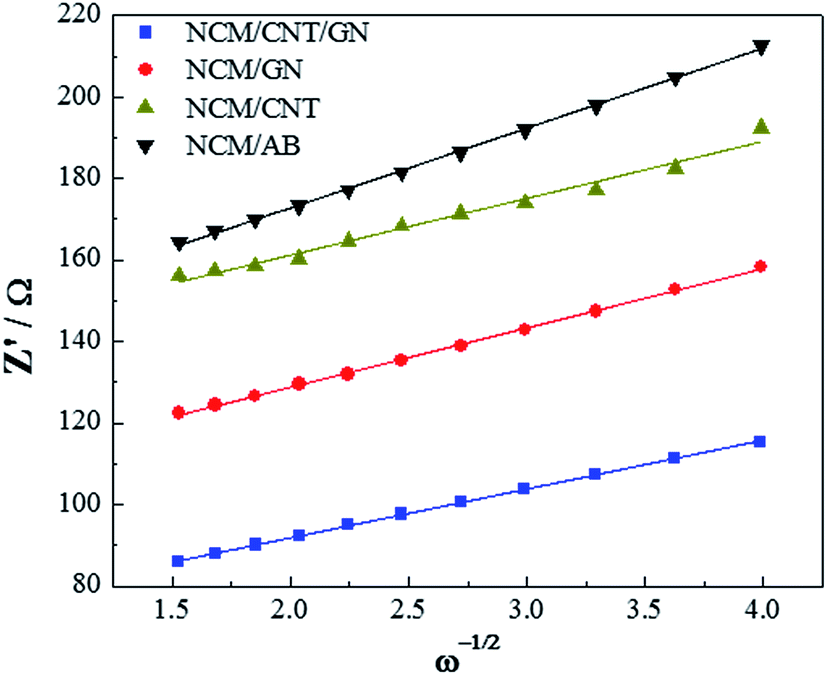 | ||
| Fig. 10 Relationship between real resistance and frequency, the slope (Warburg impedance coefficient) of which was used to calculate the sodium-ion diffusion coefficient. | ||
Conclusion
The influence of CNT + GN, GN, CNT and AB carbon conductive matrix on the electrochemical performance of LiNi1/3Co1/3Mn1/3O2 has been systematically investigated. In the structure of 3D spider web like conductive network design for the NCM/CNT/GN hybrid material, the NCM particles were well distributed among the graphene nanosheets, which alleviated the aggregation of GN. At the same time, the CNT supplied efficient linking between GN and the NCM particles, which could effectively construct a 3D electronic conducting network in the electrode of NCM/CNT/GN hybrid material. Such a unique 3D conducting network enables the fast electron and lithium ion transportation in the NCM/CNT/GN electrode, significantly ameliorating the interfacial reaction kinetics during battery cycling. As a result, the NCM/CNT/GN hybrid material exhibited the lowest electrode polarization as well as the superior rate capability and cycling performance in comparison with those of NCM/GN, NCM/CNT or NCM/AB hybrid material. The key findings of this work provide valuable clues for developing high performance cathode materials for lithium ion battery by constructing an efficient conducting network.Acknowledgements
This work was carried out with financial support from the National Natural Science Foundation of China (grant no. 51474196, 51302232, 51502250), the Science & Technology Department of Sichuan Province (grant no. 2015JY0089, 2016RZ0071), and the project of Southwest Petroleum University (grant no. X151516KCL14).References
- A. Ritchie and W. Howard, J. Power Sources, 2006, 162, 809–812 CrossRef CAS.
- S. Santhanagopalan, Q. Z. Guo, R. P. Ramadass and R. E. White, J. Power Sources, 2006, 156, 620–628 CrossRef CAS.
- P. G. Balakrishnan, R. Ramesh and T. P. Kumar, J. Power Sources, 2006, 155, 401–414 CrossRef CAS.
- R. V. Chebiam, A. M. Kannan, F. Prado and A. Manthiram, Electrochem. Commun., 2001, 3, 624–627 CrossRef CAS.
- C. Delmas, M. Ménétrier, L. Croguennec, I. Saadoune, A. Rougier, C. Pouillerie, G. Prado, M. Grüne and L. Fournès, Electrochim. Acta, 1999, 45, 243–253 CrossRef CAS.
- A. Hirano, R. Kanno and Y. Kawamoto, J. Solid State Chem., 1997, 134, 1–4 CrossRef CAS.
- A. Rougier, I. Saadoune, P. Gravereau, P. Willmann and C. Delmas, Solid State Ionics, 1996, 90, 83–90 CrossRef CAS.
- M. Yoshio, H. Noguch, J. Itoh, M. Okada and T. Mouri, J. Power Sources, 2000, 90, 176–181 CrossRef CAS.
- C. S. Hua, K. Du, C. P. Tan, Z. D. Peng, Y. B. Cao and G. R. Hu, J. Alloys Compd., 2014, 614, 264–270 CrossRef CAS.
- T. Liu, S. X. Zhao, K. Z. Wang and C. W. Nan, Electrochim. Acta, 2012, 85, 605–611 CrossRef CAS.
- X. Y. Han, Q. F. Meng, T. L. Sun and T. L. Sun, J. Power Sources, 2010, 195, 3047–3052 CrossRef CAS.
- K. M. Shaju, G. V. Subba Rao and B. V. R. Chowdari, Electrochim. Acta, 2002, 48, 145–151 CrossRef CAS.
- S. K. Hu, G. H. Cheng, M. Y. Cheng, B. J. Hwang and R. Santhanam, J. Power Sources, 2009, 188, 564–569 CrossRef CAS.
- C. H. Lu and Y. K. Lin, J. Power Sources, 2009, 189, 40–44 CrossRef CAS.
- H. B. Ren, Y. R. Wang, D. C. Li, L. H. Ren, Z. H. Peng and Y. H. Zhou, J. Power Sources, 2008, 178, 439–444 CrossRef CAS.
- X. Z. Liu, H. Q. Li, E. Yoo, M. Ishida and H. S. Zhou, Electrochim. Acta, 2012, 83, 253–258 CrossRef CAS.
- K. Araki, N. Taguchi, H. Sakaebe, K. Tatsumi and Z. Ogumi, J. Power Sources, 2014, 269, 236–243 CrossRef CAS.
- J. Cho, Y. W. Kim, B. Kim, J. G. Lee and B. Park, Angew. Chem., Int. Ed., 2003, 42, 1618–1621 CrossRef CAS PubMed.
- Y. H. Ding, P. Zhang, Z. L. Long, Y. Jiang and F. Xu, J. Alloys Compd., 2009, 487, 507–510 CrossRef CAS.
- S. K. Hu, T. C. Chou, B. J. Hwang and G. Ceder, J. Power Sources, 2006, 160, 1287–1293 CrossRef CAS.
- D. T. Liu, Z. X. Wang and L. Q. Chen, Electrochim. Acta, 2006, 51, 4199–4203 CrossRef CAS.
- Y. S. He, L. Pei, X. Z. Liao and Z. F. Ma, J. Fluorine Chem., 2007, 128, 139–143 CrossRef CAS.
- G. Y. Li, Z. L. Huang, Z. C. Zuo, Z. J. Zhang and H. H. Zhou, J. Power Sources, 2015, 281, 69–76 CrossRef CAS.
- N. N. Sinha and N. Munichandraiah, J. Am. Chem. Soc., 2009, 1, 1241–1249 CAS.
- R. Guo, P. F. Shi, X. Q. Cheng and C. Y. Du, J. Alloys Compd., 2009, 473, 53–59 CrossRef CAS.
- Q. T. Zhang, G. C. Peng, G. P. Wang, M. Z. Qu and Z. L. Yu, Solid State Ionics, 2009, 180, 698–702 CrossRef CAS.
- G. P. Wang, Q. T. Zhang, Z. L. Yu and M. Z. Qu, Solid State Ionics, 2008, 179, 263–268 CrossRef CAS.
- G. X. Wang, M. Z. Qu, Z. L. Yu and R. Z. Yuan, Mater. Chem. Phys., 2007, 105, 169–174 CrossRef CAS.
- A. Varzi, C. Täubert and M. W. Mehrens, Electrochim. Acta, 2012, 78, 17–26 CrossRef CAS.
- S. S. Jan, S. Nurgul, X. Q. Shi, H. Xia and H. Pang, Electrochim. Acta, 2014, 149, 86–93 CrossRef CAS.
- J. W. Lee, J. H. Lee, T. T. Viet, J. Y. Lee, J. S. Kim and C. H. Lee, Electrochim. Acta, 2010, 55, 3015–3021 CrossRef CAS.
- X. Y. Zhang, A. Mauger, Q. Lu, H. Groult, L. Perrigaud, F. Gendron and C. M. Julien, Electrochim. Acta, 2010, 55, 6440–6449 CrossRef CAS.
- H. Porthault, R. Baddour-Hadjean, F. Le Cras, C. Bourbon and S. Franger, Vib. Spectrosc., 2012, 62, 152–158 CrossRef CAS.
- J. J. Li, H. Q. An, J. Zhu and J. W. Zhao, Sens. Actuators, B, 2016, 235, 663–669 CrossRef CAS.
- S. S. Nanda, M. J. Kim, K. S. Yeom, S. S. A. An, H. Ju and D. K. Yi, TrAC, Trends Anal. Chem., 2016, 80, 125–131 CrossRef CAS.
- L. Li, J. C. Xu, G. H. Li, X. L. Jia, Y. F. Li, F. Yang, L. Q. Zhang, C. M. Xu, J. S. Gao, Y. Liu and Z. W. Fang, Chem. Eng. J., 2016, 284, 78–84 CrossRef CAS.
- S. Ghosh, K. Ganesan, S. R. Polaki, T. Mathews, S. Dhara, M. Kamruddin and A. K. Tyagi, Appl. Surf. Sci., 2015, 349, 576–581 CrossRef CAS.
- K. M. Shaju, G. V. S. Rao and B. V. R. Chowdari, Electrochim. Acta, 2002, 48, 145–151 CrossRef CAS.
- Z. D. Huang, X. M. Liu, S. W. Oh, B. Zhang, P. C. Ma and J. K. Kim, J. Mater. Chem. A, 2011, 21, 10777–10784 RSC.
- X. Z. Liu, H. Q. Li, D. Li, M. Ishida and H. S. Zhou, J. Power Sources, 2013, 243, 374–380 CrossRef CAS.
- F. X. Wang, Y. Liu, X. W. Wang, Z. Chang, Y. P. Wu and R. Holze, ChemElectroChem, 2015, 2, 1024–1030 CrossRef CAS.
- X. Y. Qiu, Q. C. Zhuang, Q. Q. Zhang, R. Cao, Y. H. Qiang, P. Z. Ying and S. G. Sun, J. Electroanal. Chem., 2013, 688, 393–402 CrossRef CAS.
- J. H. Park, J. H. Cho, S. B. Kim, W. S. Kim and S. Y. Lee, J. Mater. Chem., 2012, 22, 12574–12581 RSC.
- X. Li, J. Xu, P. X. Huang, W. Yang, Z. Q. Wang, M. S. Wang, Y. Huang, Y. Zhou, M. Z. Qu, Z. L. Yu and Y. H. Lin, Electrochim. Acta, 2016, 190, 69–75 CrossRef CAS.
- J. M. Zheng, P. F. Yan, W. H. Kan, C. M. Wang and A. Manthiram, J. Electrochem. Soc., 2016, 163(3), A584–A591 CrossRef CAS.
| This journal is © The Royal Society of Chemistry 2017 |