DOI:
10.1039/C7RA03209A
(Paper)
RSC Adv., 2017,
7, 32850-32860
Assembly of 1D coaxial nanoribbons into 2D multicolor luminescence array membrane endowed with tunable anisotropic electrical conductivity and magnetism via electrospinning†
Received
18th March 2017
, Accepted 11th June 2017
First published on 27th June 2017
Abstract
A flexible 2D color-tunable coaxial nanoribbon array membrane with anisotropic electrical conductivity and magnetism assembled by 1D coaxial nanoribbons is obtained via coaxial electrospinning technology using a specially designed coaxial spinneret. Each coaxial nanoribbon in the array is composed of an Fe3O4 nanoparticle (NPs)/polymethyl methacrylate (PMMA) magnetic core and [Eu(TTA)3(TPPO)2 + Tb(TTA)3(TPPO)2]/polyaniline (PANI)/PMMA [TTA = 2-thenoyltrifluoroacetone radical, TPPO = tris(N,N-tetramethylene)phosphoric acid triamide] conductive photoluminescent shell, and the array membrane is formed by aligned coaxial nanoribbons. Tunable colors ranging from green to red can be achieved in the coaxial nanoribbon array membrane by modulating the mass ratio of Eu(TTA)3(TPPO)2, Tb(TTA)3(TPPO)2, PANI and Fe3O4 NPs. Additionally, other functions such as magnetism and anisotropic electrical conductivity are conveniently exhibited by the coaxial nanoribbon array membrane to realize multifunctionality. The ratio of the conductivity parallel and perpendicular to the length direction of the nanoribbons is as high as five due to the unique nanostructure of the array membrane. Also, the magnetic performance, electrical conductivity and electrically conductive anisotropy of the coaxial nanoribbon array membrane can be tuned by modulating the contents of PANI and Fe3O4 NPs. The coaxial nanoribbon array membrane exhibits a much better luminescent performance and electrically conductive anisotropy than its counterpart composite nanoribbon array membrane. Furthermore, the design philosophy and synthetic method for the flexible coaxial nanoribbon array membrane provide a new and facile strategy for the preparation of color-tunable 2D nanomaterials with multifunctionality.
1 Introduction
Luminescent materials have received increasing attention due to their unique optical characteristics and stability,1–6 which have wide applications in various fields, such as solar-energy conversion, displays, light-emitting diodes, and biomedicine.7–11 Rare earth ions play an indispensable role in modern lighting and displays owing to the abundant emission colors based on their 4f–4f or 4f–5d transitions.12–17 Specifically, the Eu3+ ion, as one of the most common and broadly used activators, primarily emits red color which originates from its characteristic transitional emissions of 5D0,1,2–7FJ (J = 4, 3, 2, 1 and 0). Tb3+-Doped phosphors are widely applied as green emitting materials based on the 5D4–7F5 transition of Tb3+ ions.18,19 By doping Eu3+ and Tb3+ ions, materials can emit multicolor light, which have wide and important applications in computer displays, lighting and medical equipment. For example, Li et al.20,21 prepared well defined LaOF crystals and LaOF hollow spheres. By codoping Tb3+ and Eu3+ ions into the LaOF host and modulating the doping concentration of the Eu3+ ions, tunable multicolor emissions were obtained under 379 nm irradiation. Leng et al.22 successfully synthesized sphere-like and cauliflower-like hexagonal-vaterite LuBO3 via a chemical conversion route. For the prepared Eu3+/Tb3+ doped LuBO3 phosphors, the color tones were tuned from green, to green-yellow and yellow, and then to red by changing the relative doping concentrations of the Tb3+ and Eu3+ ions. Liu et al.23 synthesized a white light-emitting NaGdF4 phosphor based on efficient energy transfer between Tb3+ and Eu3+ via the conventional hydrothermal process. For NaGdF4:Tb3+,Eu3+, white emission was realized in the single phase NaGdF4 host by reasonably adjusting the molar ratios of Tb3+ and Eu3+ under ultraviolet excitation.
Recently, there has been growing research interest in the design and fabrication of novel multifunctional materials since novel multifunctional nanocomposites provide the possibility for multifunctional properties and enhanced functionality.24–26 For the purpose of developing multifunctional nanomaterials, other functions such as magnetism and electrical conduction can be conveniently assembled into luminescent nanomaterials to realize multifunctionality. Anisotropically conductive composites are a class of green materials with different resistivities in various directions, which have potential applications as functional materials in the semiconductor industry.27,28 Ra et al.29 synthesized multiwalled carbon nanotube (MWCNTs) embedded polyacrylonitrile nanofibers via electrospinning, and their conductivity parallel to the winding direction is three times higher than that perpendicular to the winding direction. Gong et al.30 studied the effect of carbon nanotube (CNT) alignment on the electrical conductivity anisotropy of CNT enhanced polymer composites. Their results showed that the anisotropic electrical property of aligned CNT/polymer composites is mainly affected by the anisotropic average conductive pathway density, which varies with the CNT alignment state in the polymer matrix. Thus, anisotropic conductive composites will have important applications in high density electrical connections in narrow spaces, such as in mobile phones, subminiature integrated circuits, microchips, and nanomachines.
Recently, some types of one-dimensional luminescent–electrical–magnetic multifunctional materials have been reported by scientists. Photoluminescent–electrical–magnetism trifunctional composite nanofibers,31 composite nanobelts,32 hollow nanofibers33,34 as well as electricity–magnetism and color-tunable microbelts35 have been constructed via electrospinning. According to previous work, the direct contact of RE compounds with deep-colored materials results in a significant reduction in luminescent intensity. Thus, in order to obtain stronger photoluminescence, the luminescent material should be isolated from deep-colored materials.
Nanoribbons are a type of nanomaterial with a special morphology,36,37 which have attracted great interest from scientists due to their anisotropy, large width–thickness ratio, photoluminescence and electrical and magnetic properties. Electrospinning is one of the most promising, simple and efficient techniques for the production of viscous solutions or melts into continuous fibers or belts with controllable diameters down to the nano or submicron scale.38–42 Electrospun products have diverse and numerous potential applications, including filtration, optical and chemical sensors, biological scaffolds and electrode materials.43–48
Herein, we prepare a novel coaxial nanoribbon array membrane composed of an Fe3O4 NPs/polymethyl methacrylate (PMMA) core and RE (RE = Eu and Tb) complexes/PANI/PMMA shell via electrospinning. By constructing type of structure, luminescent compounds can be effectively isolated from Fe3O4 NPs to avoid direct contact. Furthermore, anisotropic electrical conductivity and magnetism characteristics are introduced into the coaxial nanoribbon array membrane to achieve multifunctionality. Herein, magnetism allows the coaxial nanoribbon array membrane to be controlled under an external magnetic field. These characteristics allow the coaxial nanoribbon array membrane to be widely used in the fields of electromagnetic interference shielding, microwave absorption,49 etc. Furthermore, all the coaxial nanoribbons are arranged in the same direction by using a rolling aluminum rotary drum as the collector. It is expected that the resultant [Fe3O4/PMMA]@{[Eu(TTA)3(TPPO)2 + Tb(TTA)3(TPPO)2]/PANI/PMMA} coaxial nanoribbon array membrane will possess a high electrical conductivity ratio between the conductivity parallel and perpendicular to the length direction of the nanoribbons. This new type of coaxial nanoribbon array membrane is ideally suited for application in high density electrical connections in narrow spaces, such as in mobile phones, subminiature integrated circuits, microchips and nano/micro-machines.50,51 The structure, luminescence, anisotropic electrical conductivity and magnetism of the coaxial nanoribbon array membrane are investigated, and some satisfactory results are obtained.
2 Experimental
2.1 Chemicals
Eu2O3 (99.99%), Tb4O7 (99.99%), 2-thenoyltrifluoroacetone (HTTA), tris(N,N-tetramethylene)phosphoric acid triamide (TPPO), FeCl3·6H2O, FeSO4·7H2O, oleic acid (OA), NH4NO3, polyethylene glycol (PEG, Mr ≈ 20![[thin space (1/6-em)]](https://www.rsc.org/images/entities/char_2009.gif) 000), methyl methacrylate (MMA), ammonium persulfate (APS), benzoyl peroxide (BPO), aniline (ANI), (IS)-(+)-camphor-10 sulfonic acid (CSA), N,N-dimethylformamide (DMF), absolute alcohol, CHCl3, HNO3 and NH3·H2O. All of the chemicals were analytically pure and used as received.
000), methyl methacrylate (MMA), ammonium persulfate (APS), benzoyl peroxide (BPO), aniline (ANI), (IS)-(+)-camphor-10 sulfonic acid (CSA), N,N-dimethylformamide (DMF), absolute alcohol, CHCl3, HNO3 and NH3·H2O. All of the chemicals were analytically pure and used as received.
2.2 Preparation of Tb(TTA)3(TPPO)2 powders, Eu(TTA)3(TPPO)2 powders, PMMA and OA modified Fe3O4 NPs
Tb(TTA)3(TPPO)2 powders, Eu(TTA)3(TPPO)2 powders and PMMA were prepared via a previous method and the corresponding description of the method was shown in the ESI.† The obtained OA modified Fe3O4 NPs were synthesized through a coprecipitation (see ESI†). Fe3O4 NPs are spherical in shape (Fig. S1a†), and the particle size is 13.37 ± 0.14 nm (Fig. S1b†). The saturation magnetization of the Fe3O4 nanoparticles after coating by OA is 39.38 emu g−1 (Fig. S2†).
2.3 Preparation of spinning solutions
To prepare the spinning solution for the synthesis of the conductive photoluminescent shell (named spinning solution I), PMMA (0.5 g) was added to a mixture of ANI, CSA, CHCl3 (6 g) and DMF (0.3 g) under mechanical stirring for 48 h. At the same time, APS was added to a separate mixture of CHCl3 (4 g) and DMF (0.4 g) and stirred for 2 h. Then the solutions were refrigerated at 0 °C for 1 h. Subsequently, both solutions were mixed under mechanical agitation in a mixture of water and ice for another 2 h. The reaction system was kept at 0 °C for 24 h to produce PANI by the polymerization of aniline.52,53 Based on the reference,54 the mass percentage of RE(TTA)3(TPPO)2 to PMMA of 180% was adopted to prepare the [Fe3O4/PMMA]@{[Eu(TTA)3(TPPO)2 + Tb(TTA)3(TPPO)2]/PANI/PMMA} coaxial nanoribbon array membrane. Certain amounts of Eu(TTA)3(TPPO)2 and Tb(TTA)3(TPPO)2 complexes were introduced into the above mixture under magnetic stirring for another 12 h at room temperature to obtain spinning solution I for the shell. The quantities of the materials used for the preparation of spinning solution I are tabulated in Table 1.
Table 1 Compositions of spinning solution I
| Spinning solutions |
Composition |
| Eu(TTA)3(TPPO)2/g |
Tb(TTA)3(TPPO)2/g |
ANI/g |
CSA/g |
APS/g |
| Sa1 |
0.9 |
0 |
0.15 |
0.2809 |
0.3676 |
| Sa2 |
0.81 |
0.09 |
0.15 |
0.2809 |
0.3676 |
| Sa3 |
0.63 |
0.27 |
0.15 |
0.2809 |
0.3676 |
| Sa4 |
0.45 |
0.45 |
0.15 |
0.2809 |
0.3676 |
| Sa5 |
0.27 |
0.63 |
0.15 |
0.2809 |
0.3676 |
| Sa6 |
0.09 |
0.81 |
0.15 |
0.2809 |
0.3676 |
| Sa7 |
0 |
0.9 |
0.15 |
0.2809 |
0.3676 |
| Sa8 |
0.45 |
0.45 |
0.25 |
0.4682 |
0.6126 |
| Sa9 |
0.45 |
0.45 |
0.35 |
0.6554 |
0.8578 |
The other spinning solution (named spinning solution II) for the core of the coaxial nanoribbons was prepared as follows. Certain amounts of Fe3O4 NPs were dispersed in a mixed solvent of CHCl3 (9 g) and DMF (0.9 g) under ultrasonication for 15 min, and then PMMA (0.5 g) was introduced to the above solution under mechanical agitation for 48 h. To study the effects of Fe3O4 NPs on the properties of the coaxial nanoribbon array membrane, various amounts of Fe3O4 NPs were added to the solution. Table 2 presents the actual components of spinning solution II. The obtained coaxial nanoribbon array membrane was denoted as Sby@Sax (x = 1–9 and y = 1–3).
Table 2 Compositions of the spinning solution II
| Spinning solution |
Compositions |
| Fe3O4/g |
PMMA/g |
CHCl3/g |
DMF/g |
| Sb1 |
0.5 |
0.5 |
9 |
0.9 |
| Sb2 |
1.0 |
0.5 |
9 |
0.9 |
| Sb3 |
1.5 |
0.5 |
9 |
0.9 |
2.4 Fabrication of tunable multicolor luminescent–electrical–magnetism trifunctional coaxial nanoribbon array membrane
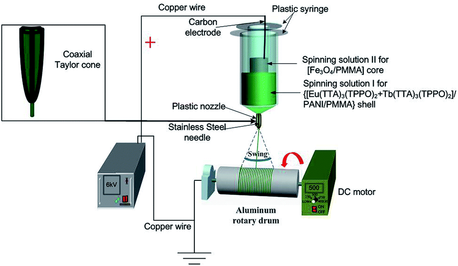
A schematic of the electrospinning process is shown in Fig. 1. Spinning solutions I and II were loaded into the outer and inner plastic syringes, respectively. A positive high voltage direct current (DC) supply was connected to the carbon electrode which was immersed in spinning solution II. The ground terminal was connected to an aluminum rotary drum, which acted as the collector. The aluminum rotary drum with a length of 20 cm and diameter of 10 cm was placed at a distance of 18 cm from the plastic spinneret, fixed horizontally, and the rotation speed was 500 rpm. The voltage was tuned to about 6 kV. The coaxial nanoribbons swung in the air due to the instability of the electrospinning process, and an array membrane with a certain width was collected on the surface of the aluminum rotary drum.
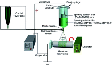 |
| | Fig. 1 Schematic illustration of the setup for the coaxial electrospinning process. | |
2.5 Fabrication of Fe3O4/[Eu(TTA)3(TPPO)2 + Tb(TTA)3(TPPO)2]/PANI/PMMA composite nanoribbon array membrane
For comparison with the coaxial nanoribbon array membrane, an Fe3O4/[Eu(TTA)3(TPPO)2 + Tb(TTA)3(TPPO)2]/PANI/PMMA composite nanoribbon array membrane was fabricated by blending the Sa4 and Sb1 solutions together, and electrospinning them via conventional single-spinneret electrospinning. The other conditions were the same as that for the fabrication of the coaxial nanoribbon array membrane.
2.6 Characterization
The as-prepared Fe3O4 NPs and [Fe3O4/PMMA]@{[Eu(TTA)3(TPPO)2 + Tb(TTA)3(TPPO)2]/PANI/PMMA} coaxial nanoribbon array membrane and composite nanoribbon array membrane were characterized via X-ray powder diffraction (XRD) on a D8 FOCUS diffractometer (Cu Kα radiation, λ = 0.154 nm, operated at 40 kV and 20 mA). The morphology and size of the Fe3O4 NPs and coaxial nanoribbon array membrane were observed via transmission electron microscopy (TEM, Jeol, JEM-2010) and scanning electron microscopy (SEM, JSM-7610F) with an energy-dispersive X-ray spectrometer (EDS) attached to the SEM. The inner structures of the coaxial nanoribbon array membrane were studied utilizing a CVM500E model biological microscope (BM). Fluorescence and the luminescence decay curves were investigated on an F-7000 Hitachi fluorescence spectrophotometer. A vibrating sample magnetometer (VSM) purchased from Quantum Design Inc. was used to determine magnetism. A Hall Effect Measurement System was adopted to detect the anisotropic electrical conductivity properties of the samples. UV-vis absorption spectra were recorded on a Shimadzu UV-1240 spectrophotometer.
3 Results and discussion
3.1 X-ray diffraction
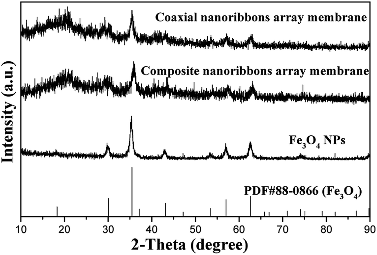
The XRD patterns of the as-obtained Fe3O4 NPs, [Fe3O4/PMMA]@{[Eu(TTA)3(TPPO)2 + Tb(TTA)3(TPPO)2]/PANI/PMMA} coaxial nanoribbon array membrane (Sb1@Sa4) and composite nanoribbon array membrane are given in Fig. 2. The diffraction peaks of the as-prepared Fe3O4 NPs are readily indexed to the cubic phase of Fe3O4 (PDF 88-0866). Obviously, only the characteristic peaks of Fe3O4 can be detected in the samples, and no other impurities peaks (e.g., Fe2O3 and FeO(OH)) are observed, which implies that a pure Fe3O4 phase was formed. The analysis results of the coaxial nanoribbon array membrane and composite nanoribbon array membrane indicate that they both contain Fe3O4 NPs, but their intensity is relatively low because of the existence of other amorphous substances.
 |
| | Fig. 2 XRD patterns of the Fe3O4 NPs, [Fe3O4/PMMA]@{[Eu(TTA)3(TPPO)2 + Tb(TTA)3(TPPO)2]/PANI/PMMA} coaxial nanoribbon array membrane (Sb1@Sa4), and composite nanoribbon array membrane with the PDF standard card of Fe3O4. | |
3.2 Morphology and structure
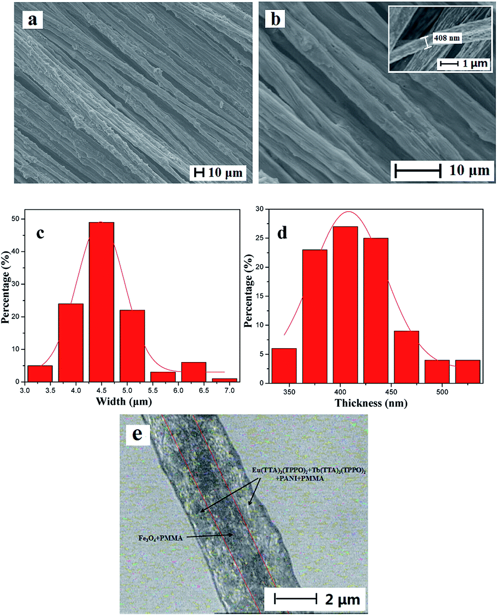
Fig. 3a and b show the SEM images of the coaxial nanoribbon array membrane at low and high magnification, respectively, which reveal that the array membrane consists of well aligned coaxial nanoribbons. The coaxial nanoribbons are 4.48 ± 0.03 μm in width (Fig. 3c) and 408.12 ± 3.87 nm in thickness (Fig. 3d). In addition, it can be observed that nearly all the broadsides of the coaxial nanoribbons in the array membrane face upwards with the rare exception. The reason for this may be that such an arrangement would cause the coaxial nanoribbons to be lay in a more stable and low potential energy state on the aluminum rotary drum. The internal structure of the coaxial nanoribbons in the array membrane was investigated via BM observation, as presented in Fig. 3e. A distinct core–shell structure is observed with a core width of ca. 1.5 μm. The core includes many deep-colored Fe3O4 NPs and the shell of the coaxial nanoribbons is blackish green due to the existence of PANI.
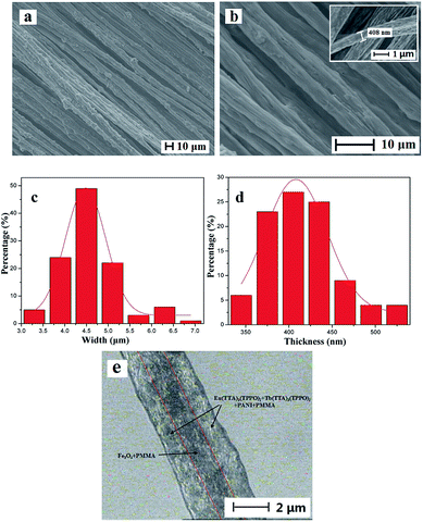 |
| | Fig. 3 SEM images of [Fe3O4/PMMA]@{[Eu(TTA)3(TPPO)2 + Tb(TTA)3(TPPO)2]/PANI/PMMA}coaxial nanoribbon array membrane (Sb1@Sa4; (a) low magnification and (b) high magnification); histograms of the width (c) and thickness (d) distributions; and BM image (e) of a single [Fe3O4/PMMA]@{[Eu(TTA)3(TPPO)2 + Tb(TTA)3(TPPO)2]/PANI/PMMA}coaxial nanoribbon; the inset of (b) shows the thickness of a single coaxial nanoribbon. | |
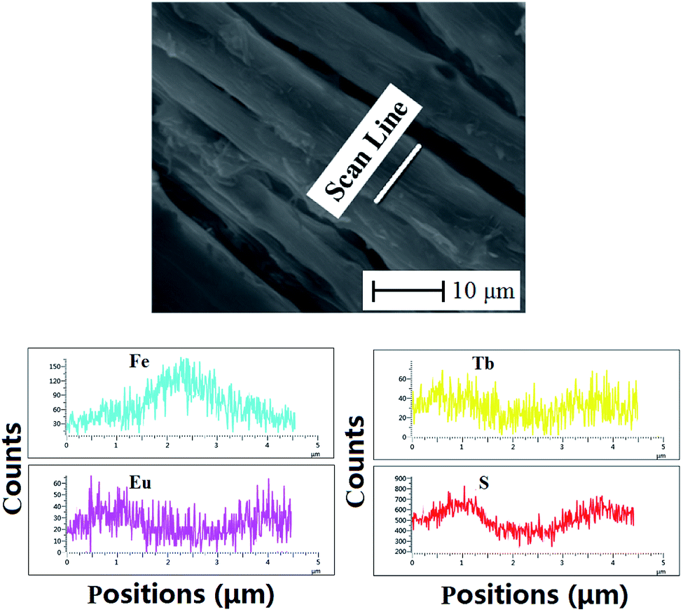
To further study the structure of the coaxial nanoribbons in the array, EDS line-scan analysis tests were carried out. As seen from Fig. 4, elemental S, Fe, Eu and Tb represent CSA doped PANI, Fe3O4, Eu(TTA)3(TPPO)2 and Tb(TTA)3(TPPO)2, respectively. Fe element exists in the middle domain of the coaxial nanoribbon. In the middle domain of the coaxial nanoribbon, the contents of S, Tb and Eu elements are lower than those on both sides, which means that PANI and RE(TTA)3(TPPO)2 (RE = Tb and Eu) only exist in the top and bottom surfaces of the middle domain of the coaxial nanoribbon. It is also discovered that elemental S, Tb and Eu without elemental Fe are dispersed on both sides of the coaxial nanoribbon. These results further confirm the coaxial structure of the coaxial nanoribbon.
 |
| | Fig. 4 EDS line-scan analysis of single [Fe3O4/PMMA]@{[Eu(TTA)3(TPPO)2 + Tb(TTA)3(TPPO)2]/PANI/PMMA} coaxial nanoribbons in array. | |
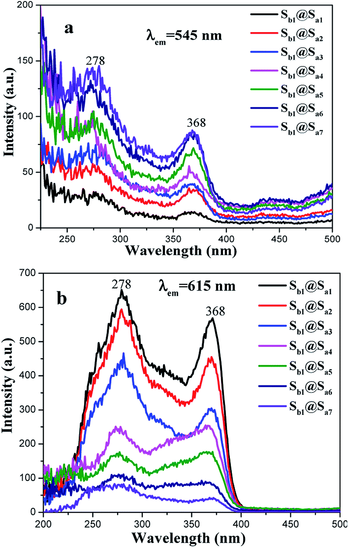
3.3 Photoluminescence property
A series of coaxial nanoribbon array membranes (samples Sb1@Sax, x = 1–7) doped with various contents of RE(TTA)3(TPPO)2 were fabricated to study the fluorescent performance of the membrane when the content of PANI to PMMA is 30% and Fe3O4 to PMMA is 1:1. As illustrated in Fig. 5 and 6, a wide band is observed in the region of 200–400 nm with a maximum at 278 nm, which could be attributed to the π → π* electron transition of the ligands. With an increase in Tb(TTA)3(TPPO)2 concentration, the fluorescence intensity gradually increases when the monitored wavelength is 545 nm (Fig. 5a). Similarly, the fluorescence intensity increases with an increase in the content of Eu(TTA)3(TPPO)2 when the monitored wavelength is 615 nm (Fig. 5b).
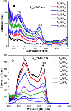 |
| | Fig. 5 Excitation spectra of samples Sb1@Sax (x = 1–7) with the monitored wavelengths of 545 nm (a) and 615 nm (b). | |
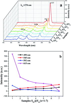 |
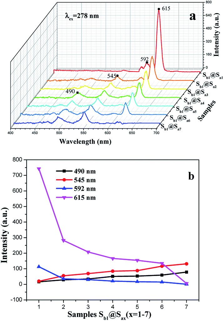
| | Fig. 6 Emission spectra (a) of samples Sb1@Sax (x = 1–7) at the PANI percentage of 30% and Fe3O4 to PMMA ratio of 1:1 and relationship between the RE complexes content and intensity of the luminescent peaks of the samples (b). | |
Under 278 nm excitation, the emission spectra of the coaxial nanoribbon array membrane doped with various contents of RE(TTA)3(TPPO)2 have several emissions peaks. The peaks located at 490 and 545 nm are due to the 5D4 → 7FJ (J = 6 and 5) transitions of Tb3+, whereas the peaks at 592 and 615 nm are ascribed to the 5D0 → 7FJ (J = 1, 2) transitions of Eu3+ (Fig. 6a). It is directly observed that the fluorescence intensity of the Tb3+ ions enhances gradually with an increase in Tb3+ concentration, whereas the emission peak of the Eu3+ ions gradually decreases. The variation trends are depicted in Fig. 6b. The energy distribution results in a change in the fluorescence intensities of Eu3+ and Tb3+. Since the matrix can absorb energy and the total mass of RE(TTA)3(TPPO)2 (RE = Eu and Tb) is fixed, the energy assigned to Eu3+ increased with an increase in Eu3+ concentration, thus resulting in the enhanced fluorescence intensity at 592 and 615 nm. Whereas, the energy assigned to Tb3+ decreased and the fluorescence intensities at 490 and 545 nm were weakened. Hence, changing the contents of the Eu(TTA)3(TPPO)2 and Tb(TTA)3(TPPO)2 complexes in the coaxial nanoribbon array membrane can tune its emission spectrum.
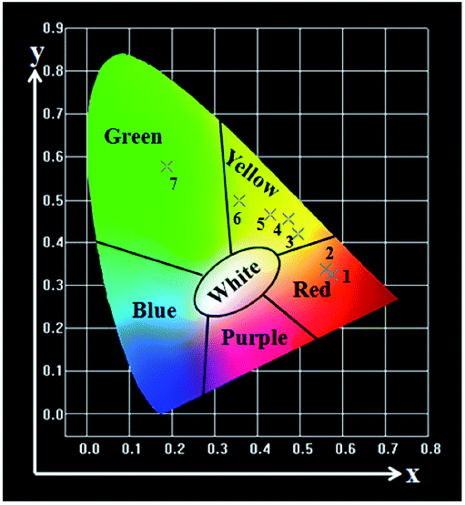
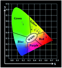
The CIE chromaticity diagram55,56 of the coaxial nanoribbon array membrane with different mass ratios of Eu(TTA)3(TPPO)2 to Tb(TTA)3(TPPO)2 complexes upon 278 nm UV lamp excitation were calculated using the CIE software based on the corresponding emission spectra shown in Fig. 6a, as represented in Fig. 7, and the data are given in Table 3. The intriguing finding is that the fluorescence color can be tuned from red, yellow to green by modulating the mass ratio of the Eu(TTA)3(TPPO)2 to Tb(TTA)3(TPPO)2 complexes.
 |
| | Fig. 7 CIE chromaticity coordinate diagram of the samples Sb1@Sax (x = 1–7) upon excitation at 278 nm. | |
Table 3 CIE chromaticity coordinates (x, y) for samples Sb1@Sax (x = 1–7) upon excitation at 278 nm
| Label |
Samples |
Concentration |
CIE (x, y) |
| 1 |
Sb1@Sa1 |
100% Eu, 0% Tb |
(0.575, 0.325) |
| 2 |
Sb1@Sa2 |
90% Eu, 10% Tb |
(0.559, 0.338) |
| 3 |
Sb1@Sa3 |
70% Eu, 30% Tb |
(0.494, 0.419) |
| 4 |
Sb1@Sa4 |
50% Eu, 50% Tb |
(0.472, 0.455) |
| 5 |
Sb1@Sa5 |
30% Eu, 70% Tb |
(0.430, 0.465) |
| 6 |
Sb1@Sa6 |
90% Eu, 10% Tb |
(0.357, 0.498) |
| 7 |
Sb1@Sa7 |
0% Eu, 100% Tb |
(0.187, 0.578) |
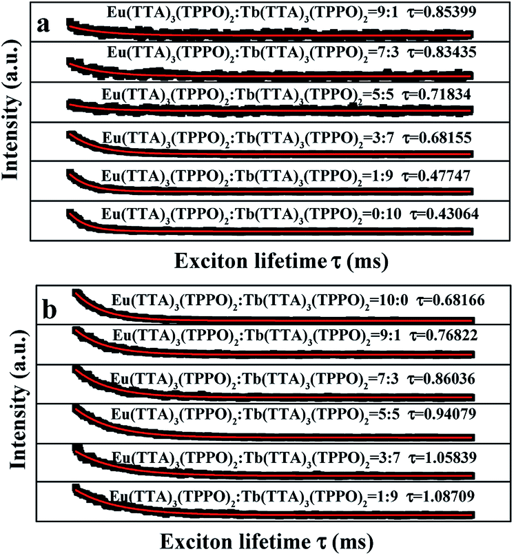
The fluorescence lifetime curves of Tb3+ and Eu3+ were measured by monitoring at the wavelengths of 545 nm and 615 nm with excitation of 278 nm as shown in Fig. 8, respectively. Intriguingly, the curves correspond to the single-exponential decay:
| It = I0exp(−t/τ) |
where,
It represents the intensity at time
t,
I0 is the initial intensity,
t is the decay time and
τ is the exciton lifetime. As indicated in
Fig. 8, the fluorescence lifetime values of Tb
3+ gradually increase with a decrease in Tb
3+ content. The same conclusion can be drawn for the Eu
3+ ions, where the lifetime of the Eu
3+ ions increases with a decrease in Eu
3+ content. The following are the possible reasons for this result. When the concentration of the Tb(TTA)
3(TPPO)
2 complex in the coaxial nanoribbon array membrane decreases and the relative concentration of Eu(TTA)
3(TPPO)
2 increases, the distance among the Tb
3+ ions in the Tb(TTA)
3(TPPO)
2 molecular clusters in the coaxial nanoribbon array membrane increases, which leads to a reduction in the energy transfer among Tb
3+ to Tb
3+ and prolongs the fluorescence lifetime of Tb
3+. On the other hand, adding more Eu(TTA)
3(TPPO)
2 into PMMA leads to the formation of more aggregates of Eu(TTA)
3(TPPO)
2. The exciton migration between the Eu(TTA)
3(TPPO)
2 molecules shortens the fluorescence lifetime of Eu
3+.
57
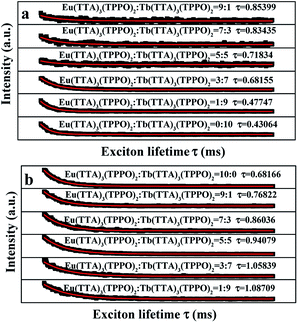 |
| | Fig. 8 Lifetime curves of Tb3+ (a) and Eu3+ (b) in the samples Sb1@Sax (x = 1–7). | |
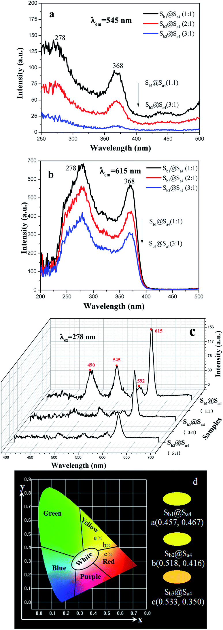
Besides, the fluorescent properties of the [Fe3O4/PMMA]@{[Eu(TTA)3(TPPO)2 + Tb(TTA)3(TPPO)2]/PANI/PMMA} coaxial nanoribbon array membrane with different PANI contents (Sb1@Sa4, Sb1@Sa8 and Sb1@Sa9) were also studied at the Fe3O4 to PMMA ratio of 1:1. It can be seen from Fig. 9a–c that fluorescence intensity diminishes with an increase in the content of PANI. Fig. 9d displays the CIE chromaticity diagram of the coaxial nanoribbon array membranes with different PANI contents upon 278 nm UV lamp excitation. It can be found that the luminescence color tunes more green with the addition of more PANI owing to the stronger absorption of red light by PANI. Similarly, when the amount of Fe3O4 NPs (Sb1@Sa4, Sb2@Sa4 and Sb3@Sa4) increases, both excitation and emission intensities of the coaxial nanoribbons decrease (Fig. 10a–c). Fig. 10d presents the CIE coordinate diagram of coaxial nanoribbon array membrane containing different Fe3O4 contents upon 278 nm UV lamp excitation. It can be found that the luminescence color of the coaxial nanoribbon array membrane could be shifted with the addition of more Fe3O4.
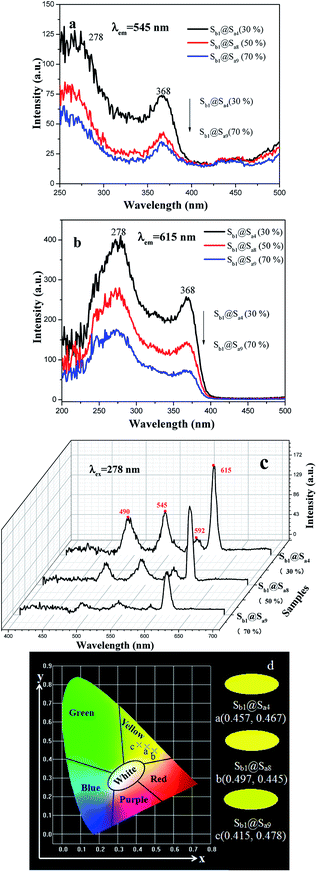 |
| | Fig. 9 Excitation spectra with the monitoring wavelengths of 545 nm (a) and 615 nm (b); emission spectra (c) and CIE chromaticity coordinate diagram (d) of the [Fe3O4/PMMA]@{[Eu(TTA)3(TPPO)2 + Tb(TTA)3(TPPO)2]/PANI/PMMA} coaxial nanoribbon array membrane doped with different contents of PANI. | |
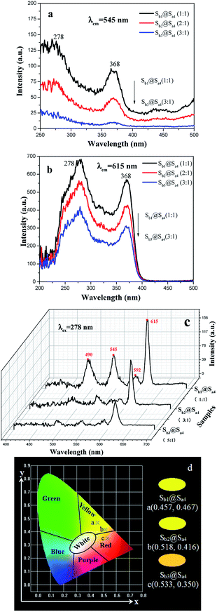 |
| | Fig. 10 Excitation spectra with the monitoring wavelengths of 545 nm (a) and 615 nm (b), emission spectra (c) and CIE chromaticity coordinate diagram (d) of [Fe3O4/PMMA]@{[Eu(TTA)3(TPPO)2 + Tb(TTA)3(TPPO)2]/PANI/PMMA} coaxial nanoribbon array membrane doped with different contents of Fe3O4 NPs. | |
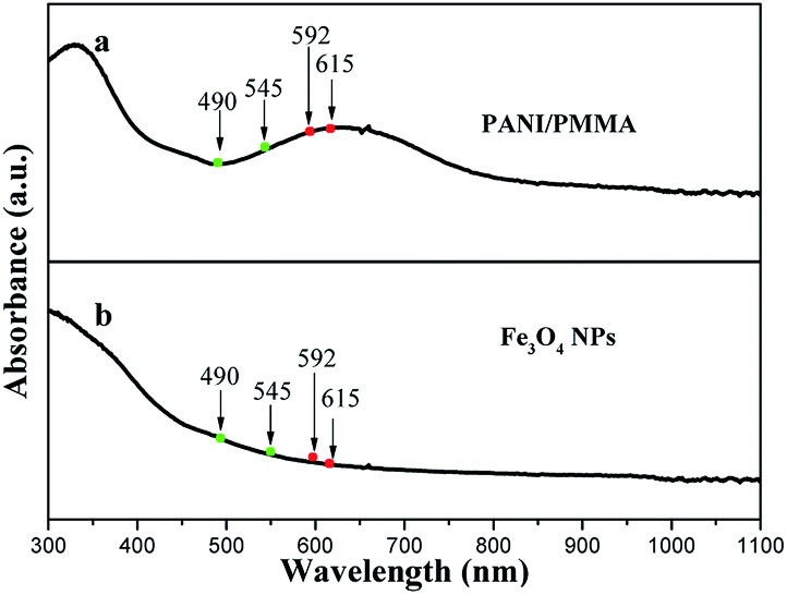
The above results can be explained by the light absorption of Fe3O4 NPs and PANI. The absorption spectra of the Fe3O4 NPs and PANI are shown in Fig. 11. It can be observed that PANI doped PMMA and Fe3O4 NPs strongly absorb light in the ultraviolet (<400 nm) and visible (400–800 nm) light regions. Therefore, the exciting light and emitting light are absorbed by the PANI and Fe3O4 NPs, which results in the fact that the intensities of exciting and emitting light are diminished and more light is absorbed with the addition of more PANI and Fe3O4 NPs into the coaxial nanoribbon array membrane. On the other hand, because PANI has different absorbances at different wavelengths of light, as well as Fe3O4 NPs, as seen in Fig. 11, the different wavelengths of light emitted from the coaxial nanoribbon array membrane are unequally absorbed by PANI and Fe3O4, thus the emitted colors are shifted.
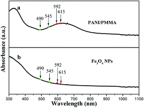 |
| | Fig. 11 Ultraviolet-visible absorption spectra of PANI/PMMA (a) and Fe3O4 NPs (b). | |
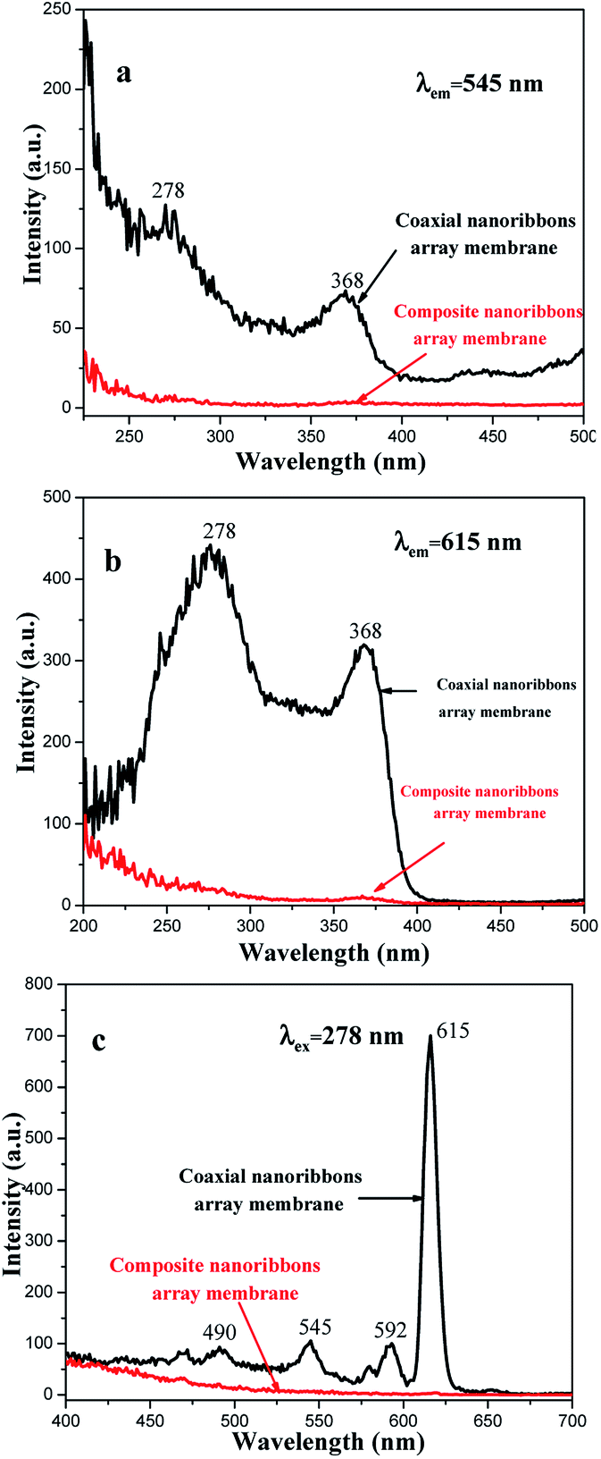
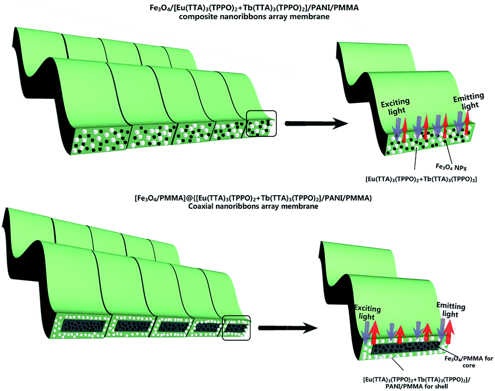
From the contrast between the coaxial nanoribbon array membrane (Sb1@Sa4) and Fe3O4/[Eu(TTA)3(TPPO)2 + Tb(TTA)3(TPPO)2]/PANI/PMMA composite nanoribbon array membrane, as shown in Fig. 12, both the excitation and emission intensities of the coaxial nanoribbon array membrane are much stronger than those of the Fe3O4/[Eu(TTA)3(TPPO)2 + Tb(TTA)3(TPPO)2]/PANI/PMMA composite nanoribbon array membrane. The emission intensity of the coaxial nanoribbon array membrane is about 100 times higher than that of the composite nanoribbon array membrane, which is due to the isolation of [Eu(TTA)3(TPPO)2 + Tb(TTA)3(TPPO)2] from the Fe3O4 NPs. [Eu(TTA)3(TPPO)2 + Tb(TTA)3(TPPO)2], PANI and Fe3O4 NPs are loosely mixed in the composite nanoribbon array membrane, as shown in Fig. 13, where RE(TTA)3(TPPO)2 (RE = Eu and Tb) directly contacts the Fe3O4 NPs which strongly absorb and weaken the excitation and emission light, leading to a severe decrease in luminescent intensity. On the contrary, in the coaxial nanoribbon array membrane, the Fe3O4 NPs are isolated from the Eu(TTA)3(TPPO)2 and Tb(TTA)3(TPPO)2 complexes in their own domains of the coaxial nanoribbon array membrane, therefore the excitation and emission light in the {[Eu(TTA)3(TPPO)2 + Tb(TTA)3(TPPO)2]/PANI/PMMA} domain are almost unaffected by the Fe3O4 NPs. This result fully shows that the coaxial nanoribbon array membrane exhibits a better fluorescent performance than the Fe3O4/[Eu(TTA)3(TPPO)2 + Tb(TTA)3(TPPO)2]/PANI/PMMA composite nanoribbon array membrane. Therefore, the higher luminescent intensity of the coaxial nanoribbon array membrane was obtained by separating Eu(TTA)3(TPPO)2 and Tb(TTA)3(TPPO)2 from the Fe3O4 NPs.
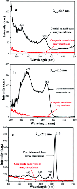 |
| | Fig. 12 Excitation spectra with the monitoring wavelengths of 545 nm (a) and 615 nm (b), and emission spectra (c) of the coaxial nanoribbon array membrane (Sb1@Sa4) and its counterpart composite nanoribbon array membrane. | |
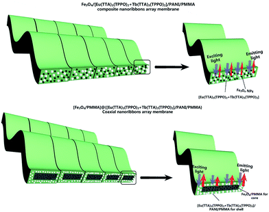 |
| | Fig. 13 Schematic diagram showing the excitation and emission light in the composite nanoribbon array membrane and [Fe3O4/PMMA]@{[Eu(TTA)3(TPPO)2 + Tb(TTA)3(TPPO)2]/PANI/PMMA} coaxial nanoribbon array membrane. | |
3.4 Electrical conductivity analysis
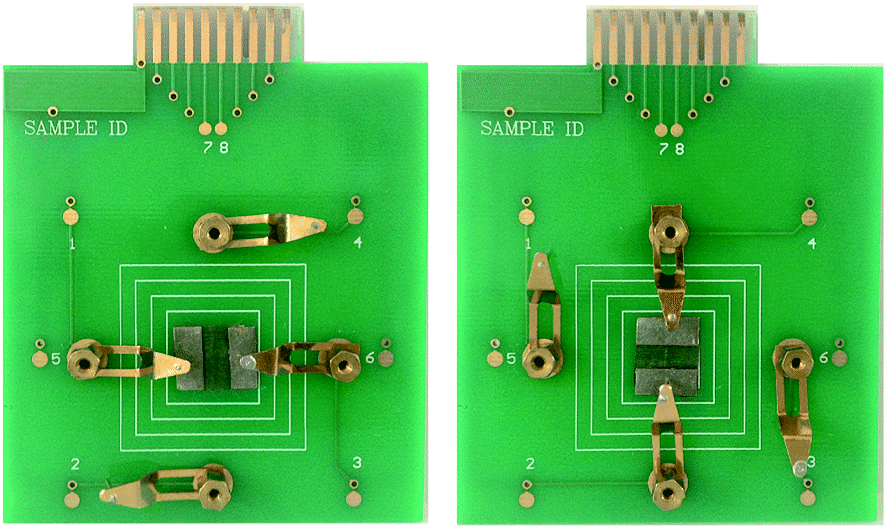
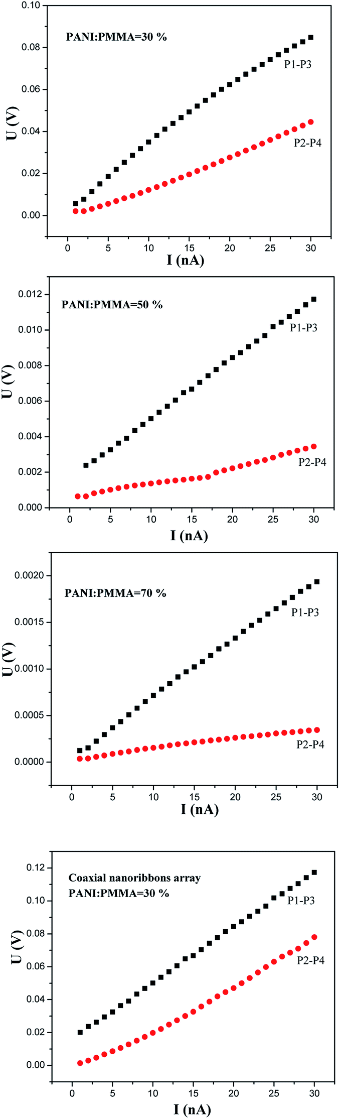
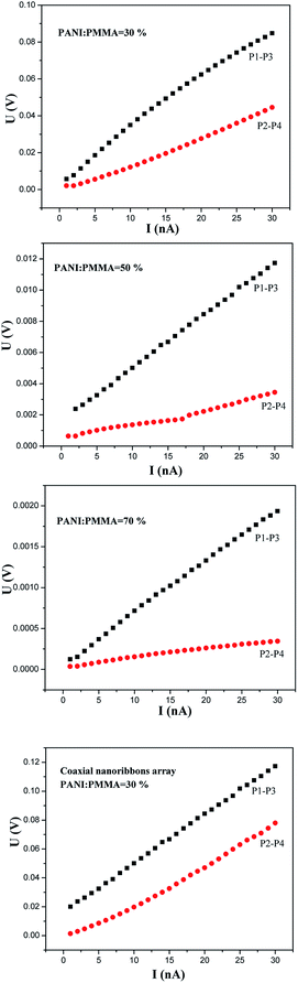
In order to study the anisotropic conductivity of the [Fe3O4/PMMA]@{[Eu(TTA)3(TPPO)2 + Tb(TTA)3(TPPO)2]/PANI/PMMA} coaxial nanoribbon array membrane and composite nanoribbon array membrane, a piece of soldering tin was cut into two pieces with length and width of ca. 1 cm and ca. 0.5 cm, respectively, and then the two pieces of soldering were pressed onto the nanoribbon array membrane, as indicated in Fig. 14. Subsequently, the four pins of a Hall Effect Measurement System were pressed on the two pieces of soldering tin. The relationships of voltage and current between P1 and P3 and P2 and P4 were recorded by the Hall Effect Measurement System, and the results are presented in Fig. 15. It can be seen that the conductance parallel to the length direction of the nanoribbons (P1–P3) is higher than that perpendicular to the length direction of the nanoribbons (P2–P4), which demonstrates that the coaxial nanoribbon array membrane possesses anisotropic conductivity. Since each coaxial nanoribbon has a conductive-photoluminescent shell and nearly all the broadsides of the coaxial nanoribbons face upwards, electrons can move along the length direction of the nanoribbons, whereas some interfaces among the coaxial nanoribbons hinder the movement of electrons to some extent along with perpendicular direction. The conductivities of coaxial nanoribbon array membranes containing different amounts of PANI between P1 and P3 and P2 and P4 are tabulated in Table 4. Evidently, with an increase in the dosage of PANI introduced into the coaxial nanoribbons array membrane, higher conductivity can be achieved in the coaxial nanoribbon array membrane. Its conductivity parallel to the length direction of the nanoribbons is ca. two to five times higher than that perpendicular to the length direction of the nanoribbons. Thus, the anisotropic electrical conductivity of the coaxial nanoribbon array membrane can be tuned because PANI is consecutive in the shell of coaxial nanoribbon array membrane and may form a conducting network more easily, which renders more efficient charge transport.
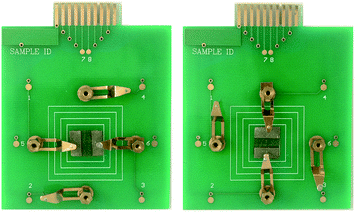 |
| | Fig. 14 Arrangement of the four contact points on the [Fe3O4/PMMA]@{[Eu(TTA)3(TPPO)2 + Tb(TTA)3(TPPO)2]/PANI/PMMA} coaxial nanoribbon array membrane. | |
 |
| | Fig. 15 Relationships between the voltage and current of the samples doped with various amounts of PANI between P1 and P3 and P2 and P4. | |
Table 4 Conductivity of the samples containing different amounts of PANI between P1 and P3 and P2 and P4
| Samples |
Conductivity (S cm−1) |
| Parallel (X) (P1–P3) |
Perpendicular (Y) (P2–P4) |
X/Y |
| Composite nanoribbon array membrane |
4.795 × 10⁻⁷ |
2.054 × 10⁻⁷ |
2.33 |
| Sb1@Sa4 (30%) |
7.819 × 10⁻⁷ |
3.048 × 10⁻⁷ |
2.57 |
| Sb1@Sa8 (50%) |
7.588 × 10⁻⁶ |
2.238 × 10⁻⁶ |
3.39 |
| Sb1@Sa9 (70%) |
7.143 × 10⁻⁵ |
1.452 × 10⁻⁵ |
4.92 |
The Fe3O4/[Eu(TTA)3(TPPO)2 + Tb(TTA)3(TPPO)2]/PANI/PMMA composite nanoribbon array membrane has weak anisotropic conductivity. Its conductivity parallel to the length direction of the nanoribbons is about two times higher than that perpendicular to the length direction of the nanoribbons. Additionally, the conductivity of the Fe3O4/[Eu(TTA)3(TPPO)2 + Tb(TTA)3(TPPO)2]/PANI/PMMA composite nanoribbon array membrane is lower than that of coaxial nanoribbon array membrane (sample Sb1@Sa4) under the same components and contents of the two types of nanostructures. The reason for this is probably that insulative materials such as Fe3O4 NPs and RE(TTA)3(TPPO)2 (RE = Eu and Tb) are dispersed in the Fe3O4/[Eu(TTA)3(TPPO)2 + Tb(TTA)3(TPPO)2]/PANI/PMMA composite nanoribbon array membrane, which hinders the formation of a continuous conductive network.
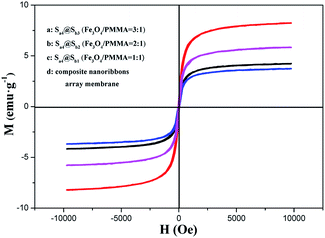
3.5 Magnetic property
Fig. 16 reveals the hysteresis loops for the Fe3O4/[Eu(TTA)3(TPPO)2 + Tb(TTA)3(TPPO)2]/PANI/PMMA composite nanoribbon array membranes and the [Fe3O4/PMMA]@{[Eu(TTA)3(TPPO)2 + Tb(TTA)3(TPPO)2]/PANI/PMMA} coaxial nanoribbon array membrane containing various mass ratios of Fe3O4 NPs, and the data are given in Table 5. It is found that the saturation magnetization of the [Fe3O4/PMMA]@{[Eu(TTA)3(TPPO)2 + Tb(TTA)3(TPPO)2]/PANI/PMMA} coaxial nanoribbon array membrane increases with the incorporating of more Fe3O4 NPs in the core, which indicates that the magnetism of the coaxial nanoribbon array membrane can be modulated. Besides, the saturation magnetization of the coaxial nanoribbon array membrane (Sb1@Sa4) is 4.23 emu g−1 which is close to that of its counterpart Fe3O4/[Eu(TTA)3(TPPO)2 + Tb(TTA)3(TPPO)2]/PANI/PMMA composite nanoribbon array membrane (3.74 emu g−1). By combining the analyses of magnetism, electrical conductivity and fluorescence, it is found that the coaxial nanoribbon array membrane has similar magnetic properties to the composite nanoribbon array membrane, whereas the fluorescent intensity and anisotropic electrical conductivity of the coaxial nanoribbon array membrane is much higher than that of the composite nanoribbon array membrane, which further indicates that the coaxial nanoribbon array membrane possess better luminescent–electrical–magnetic performance than its counterpart composite nanoribbon array membrane.
 |
| | Fig. 16 Hysteresis loops of the composite nanoribbon array membranes and [Fe3O4/PMMA]@{[Eu(TTA)3(TPPO)2 + Tb(TTA)3(TPPO)2]/PANI/PMMA} coaxial nanoribbon array membrane. | |
Table 5 Saturation magnetization of the composite nanoribbon array membrane and [Fe3O4/PMMA]@{[Eu(TTA)3(TPPO)2 + Tb(TTA)3(TPPO)2]/PANI/PMMA} coaxial nanoribbon array membrane
| Sample |
Saturation magnetization (Ms)/emu g−1 |
| Composite nanoribbons array membrane |
3.74 |
| Sb1@Sa4 (Fe3O4:PMMA = 1:1) |
4.23 |
| Sb2@Sa4 (Fe3O4:PMMA = 2:1) |
5.82 |
| Sb3@Sa4 (Fe3O4:PMMA = 3:1) |
8.23 |
4 Conclusions
A novel 2D multicolor luminescent array membrane [Fe3O4/PMMA]@{[Eu(TTA)3(TPPO)2 + Tb(TTA)3(TPPO)2]/PANI/PMMA} endowed with tunable anisotropic electrical conductivity and magnetism was successfully fabricated via electrospinning using a specially designed and assembled coaxial spinneret. The 2D multicolor luminescent array membrane is assembled by 1D coaxial nanoribbons, in which the coaxial nanoribbons are arranged in the same direction and all their broadsides nanoribbons face upwards. Each coaxial nanoribbon in the array is composed of an Fe3O4/PMMA magnetic core and [Eu(TTA)3(TPPO)2 + Tb(TTA)3(TPPO)2]/PANI/PMMA conductive-photoluminescent shell. Delightfully, tunable colors from green to red emission colors can be obtained by modulating the molar ratio of Eu3+ and Tb3+ as well as the ratio of PANI and Fe3O4. This unique nanostructure greatly promotes conductive anisotropy, in which the ratio of conductivity parallel and perpendicular to the length direction of the nanoribbons is as high as five. The anisotropic electrical conductivity and magnetism of the coaxial nanoribbons array membrane can be adjusted by modulating the contents of PANI and Fe3O4 NPs. This work presents an excellent method for the fabrication of innovative 2D multifunctional nanocomposites possessing anisotropic electrical conductivity and magnetism, which have possible applications in many future fields, such as in mobile phones and subminiature integrated circuits.
Acknowledgements
This work was financially supported by National Natural Science Foundation of China (51573023, 50972020), Natural Science Foundation of Jilin Province (20170101101JC), the Open Project Program of Key Laboratory of Preparation and Application of Environmentally Friendly Materials (Jilin Normal University), Ministry of Education, China (No. 2017003), Youth Foundation of Changchun University of Science and Technology (No. XQNJJ-2016-01).
Notes and references
- F. Wang, Y. Han, C. S. Lim, Y. Lu, J. Wang, J. Xu, H. Chen, C. Zhang, M. Hong and X. Liu, Nature, 2010, 463, 1061–1065 CrossRef CAS PubMed.
- K. S. Sohn, J. M. Lee and N. Shin, Adv. Mater., 2003, 15, 2081–2084 CrossRef CAS.
- P. Yang, S. Gai and J. Lin, Chem. Soc. Rev., 2012, 41, 3679–3698 RSC.
- S. Gai, P. Yang, C. Li, W. Wang, Y. Dai, N. Niu and J. Lin, Adv. Funct. Mater., 2010, 20, 1166–1172 CrossRef CAS.
- S. Huang, J. Xu, Z. Zhang, X. Zhang, L. Wang, S. Gai, F. He, N. Niu, M. Zhang and P. Yang, J. Mater. Chem., 2012, 22, 16136–16144 RSC.
- N. Niu, P. Yang, F. He, X. Zhang, S. Gai, C. Li and J. Lin, J. Mater. Chem., 2012, 22, 10889–10899 RSC.
- S. Zhou, W. Zheng, Z. Chen, D. Tu, Y. Liu, E. Ma, R. Li, H. Zhu, M. Huang and X. Chen, Angew. Chem., Int. Ed., 2014, 53, 12498–12502 CAS.
- D. Yin, X. Cao, L. Zhang, J. Tang, W. Huang, Y. Han and M. Wu, Dalton Trans., 2015, 44, 11147–11154 RSC.
- Y. Liu, D. Tu, H. Zhu and X. Chen, Chem. Soc. Rev., 2013, 42, 6924–6958 RSC.
- C. C. Lin and R.-S. Liu, J. Phys. Chem. Lett., 2011, 2, 1268–1277 CrossRef CAS PubMed.
- K. Li, Y. Zhang, X. Li, M. Shang, H. Lian and J. Lin, Phys. Chem. Chem. Phys., 2015, 17, 4283–4292 RSC.
- H. Liu, T. Chu, Z. Rao, S. Wang, Y. Yang and W.-T. Wong, Adv. Opt. Mater., 2015, 3, 1545–1550 CrossRef CAS.
- X. Zhang and M. Gong, Ind. Eng. Chem. Res., 2015, 54, 7632–7639 CrossRef CAS.
- M. Zhang, Y. Liang, R. Tang, D. Yu, M. Tong, Q. Wang, Y. Zhu, X. Wu and G. Li, RSC Adv., 2014, 4, 40626–40637 RSC.
- P. Huang, W. Zheng, S. Zhou, D. Tu, Z. Chen, H. Zhu, R. Li, E. Ma, M. Huang and X. Chen, Angew. Chem., Int. Ed., 2014, 53, 1252–1257 CrossRef CAS PubMed.
- P. Chen, Q. Li, S. Grindy and N. Holten-Andersen, J. Am. Chem. Soc., 2015, 137, 11590–11593 CrossRef CAS PubMed.
- X. Liu, W. Hou, X. Yang and J. Liang, CrystEngComm, 2014, 16, 1268–1276 RSC.
- S. Xu, P. Li, Z. Wang, T. Li, Q. Bai, J. Sun and Z. Yang, J. Mater. Chem. C, 2015, 3, 9112–9121 RSC.
- C. Zeng, Y. Hu, Z. Xia and H. Huang, RSC Adv., 2015, 5, 68099–68108 RSC.
- R. Li, G. Yu, Y. Liang, N. Zhang, Y. Liu and S. Gan, J. Colloid Interface Sci., 2015, 460, 273–280 CrossRef CAS PubMed.
- R. Li, L. Li, Y. Liang, N. Zhang, Y. Liu and S. Gan, Phys. Chem. Chem. Phys., 2015, 17, 21485–21491 RSC.
- Z. Leng, H. Xiong, L. Li, N. Zhang, Y. Liu and S. Gan, J. Alloys Compd., 2015, 646, 632–638 CrossRef CAS.
- L. Liu, Y. Liang, L. Li, L. Zou and S. Gan, CrystEngComm, 2015, 17, 7754–7761 RSC.
- Y. R. Weng, J. Zhao, S. Y. Yu and S. Y. Song, CrystEngComm, 2014, 16, 6257–6262 RSC.
- Y. Gong, J. Dai, H. Li, X. Wang, H. Xiong, Q. Zhang, P. Li, C. Yi, Z. Xu, H. Xu and P. K. Chu, J. Biomater. Appl., 2015, 30, 201–211 CrossRef CAS PubMed.
- D. Li, Q. Ma, X. Xi, X. Dong, W. Yu, J. Wang and G. Liu, Chem. Eng. J., 2017, 309, 230–239 CrossRef CAS.
- B. Li, Y.-C. Zhang, Z.-M. Li, S.-N. Li and X.-N. Zhang, J. Phys. Chem. B, 2010, 114, 689–696 CrossRef CAS PubMed.
- Y. J. Jung, S. Kar, S. Talapatra, C. Soldano, G. Viswanathan, X. Li, Z. Yao, F. S. Ou, A. Avadhanula, R. Vajtai, S. Curran, O. Nalamasu and P. M. Ajayan, Nano Lett., 2006, 6, 413–418 CrossRef CAS PubMed.
- E. J. Ra, K. H. An, K. K. Kim, S. Y. Jeong and Y. H. Lee, Chem. Phys. Lett., 2005, 413, 188–193 CrossRef CAS.
- S. Gong, Z. H. Zhu and S. A. Meguid, Polymer, 2015, 56, 498–506 CrossRef CAS.
- S. Sheng, Q. Ma, X. Dong, N. Lv, J. Wang, W. Yu and G. Liu, J. Mater. Sci.: Mater. Electron., 2014, 25, 1309–1316 CrossRef CAS.
- S. Sheng, Q. Ma, X. Dong, N. Lv, J. Wang, W. Yu and G. Liu, J. Mater. Sci.: Mater. Electron., 2014, 25, 2279–2286 CrossRef CAS.
- Y. Liu, Q. Ma, M. Yang, X. Dong, Y. Yang, J. Wang, W. Yu and G. Liu, Chem. Eng. J., 2016, 284, 831–840 CrossRef CAS.
- Y. Liu, Q. Ma, X. Dong, W. Yu, J. Wang and G. Liu, Phys. Chem. Chem. Phys., 2015, 17, 22977–22984 RSC.
- K. Lun, Q. Ma, M. Yang, X. Dong, Y. Yang, J. Wang, W. Yu and G. Liu, Chem. Eng. J., 2015, 279, 231–240 CrossRef CAS.
- L. Jiang, S. Yinghui, H. Peng, L.-J. Li, T. Wu, J. Ma, F. Y. Chiang Boey, X. Chen and L. Chi, Small, 2011, 7, 1949–1953 CrossRef CAS PubMed.
- J. Zhou, J. Zeng, J. Grant, H. Wu and Y. Xia, Small, 2011, 7, 3308–3316 CrossRef CAS PubMed.
- L. Han, Q. Ma and X. Dong, RSC Adv., 2015, 5, 95674–95681 RSC.
- F. Bi, X. Dong, J. Wang and G. Liu, New J. Chem., 2015, 39, 3444–3451 RSC.
- D. Yin, Q. Ma, X. Dong, N. Lv, J. Wang, W. Yu and G. Liu, ChemPlusChem, 2015, 80, 568–575 CrossRef CAS.
- F. Bi, X. Dong, J. Wang and G. Liu, ChemPlusChem, 2014, 79, 1713–1719 CAS.
- X. Xi, Q. Ma, X. Dong, J. Wang, W. Yu and G. Liu, IEEE Trans. Nanotechnol., 2015, 14, 243–249 CrossRef CAS.
- W. Sambaer, M. Zatloukal and D. Kimmer, Chem. Eng. Sci., 2011, 66, 613–623 CrossRef CAS.
- J. M. Corres, Y. R. Garcia, F. J. Arregui and I. R. Matias, IEEE Sens. J., 2011, 11, 2383–2387 CrossRef.
- A. Townsend-Nicholson and S. N. Jayasinghe, Biomacromolecules, 2006, 7, 3364–3369 CrossRef CAS PubMed.
- K. Xu, S. Li, J. Yang, H. Xu and J. Hu, J. Alloys Compd., 2016, 678, 120–125 CrossRef CAS.
- Z. Wang, Q. Ma, X. Dong, D. Li, X. Xi, W. Yu, J. Wang and G. Liu, ACS Appl. Mater. Interfaces, 2016, 8, 26226–26234 CAS.
- Z. Wang, Q. Ma, X. Dong, D. Li, X. Xi, W. Yu, J. Wang and G. Liu, Phys. Chem. Chem. Phys., 2017, 19, 118–126 RSC.
- D. Zhang, J. Cheng, X. Yang, B. Zhao and M. Cao, J. Mater. Sci., 2014, 49, 7221–7230 CrossRef CAS.
- Q. Ma, J. Wang, X. Dong, W. Yu and G. Liu, RSC Adv., 2015, 5, 2523–2530 RSC.
- J. Song, M. Chen, M. B. Olesen, C. Wang, R. Havelund, Q. Li, E. Xie, R. Yang, P. Boggild, C. Wang, F. Besenbacher and M. Dong, Nanoscale, 2011, 3, 4966–4971 RSC.
- S. Palaniappan and M. Sairam, J. Appl. Polym. Sci., 2008, 108, 825–832 CrossRef CAS.
- Y. Xia, J. M. Wiesinger, A. G. MacDiarmid and A. J. Epstein, Chem. Mater., 1995, 7, 443–445 CrossRef CAS.
- S. Sheng, Q. Ma, X. Dong, N. Lv, J. Wang, W. Yu and G. Liu, J. Mater. Sci.: Mater. Electron., 2014, 25, 2279–2286 CrossRef CAS.
- L. Chittka, J. Comp. Physiol., A, 1992, 170, 533–543 Search PubMed.
- A. R. Robertson, Color Res. Appl., 1977, 2, 7–11 CrossRef.
- Q. Ma, W. Yu, X. Dong, J. Wang and G. Liu, Nanoscale, 2014, 6, 2945–2952 RSC.
Footnote |
| † Electronic supplementary information (ESI) available. See DOI: 10.1039/c7ra03209a |
|
| This journal is © The Royal Society of Chemistry 2017 |
Click here to see how this site uses Cookies. View our privacy policy here. 
 Open Access Article
 This Open Access Article is licensed under a
  *a,
Zhelin Liua,
Jinxian Wang
*a,
Zhelin Liua,
Jinxian Wang