
 Open Access Article
 This Open Access Article is licensed under a
 Creative Commons Attribution 3.0 Unported Licence
A macro-porous graphene oxide-based membrane as a separator with enhanced thermal stability for high-safety lithium-ion batteries†
Haiyang Liao a,
Haiyan Zhang*ab,
Gai Qina,
Zhenghui Liab,
Liuqing Lia and
Haoqun Hongab
a,
Haiyan Zhang*ab,
Gai Qina,
Zhenghui Liab,
Liuqing Lia and
Haoqun Hongab
aSchool of Materials and Energy, Guangdong University of Technology, Guangzhou 510006, China. E-mail: hyzhang@gdut.edu.cn
bGuangdong Provincial Key Laboratory of Functional Soft Condensed Matter, Guangdong University of Technology, Guangzhou 510006, China
First published on 20th April 2017
Abstract
To develop a separator with remarkable thermal-resistance for high-safety lithium-ion (Li-ion) batteries, a graphene oxide (GO)-grafted hyper-branched polyether (GO-g-HBPE) macro-porous membrane without any polymer binder was designed and prepared using polystyrene (PS) nanoparticles as hard templates. GO (inorganic part) provides the membrane-formation ability for GO-g-HBPE separator and HBPE (polymer part) imparts excellent affinity with the liquid electrolyte (158% for liquid electrolyte uptake). The GO-g-HBPE membrane, serving as a separator for the batteries, exhibited robust thermal dimensional stability with no dimensional changes at 200 °C for 0.5 h. Moreover, it shows a better electrochemical performance (cycle performance and rate capability) than a commercialized PP separator, implying a promising potential for application in high-safety and high-power Li-ion batteries.
1. Introduction
Fossil fuels as an energy source have been widely exploited and applied in energy devices in past decades. However, because of their non-renewable nature, these energy sources are becoming scarce and their low energy transformation efficiency severely restricts applications in high-power and high-energy density devices.1–5 The research and development of green, clean and sustainable energy systems has become the main focus of the world.6 Li-ion batteries due to their high energy density, long cycle life and environmental friendliness have been identified as a potential choice to substitute fossil fuels.7,8 Much research has been conducted on Li-ion batteries recently, and their applications have been expanded to the field of electric vehicles and electric power tools.9 Unfortunately, the safety aspect of the present Li-ion batteries is still the main restraining factor in the development of energy storage devices. The separator plays a critical role in preventing the physical contact between positive and negative electrodes, which further triggers short-circuiting and thermal runaway.10 However, commercial polyolefin separators (polyethylene (PE) and polypropylene (PP)), suffer from a low melting temperature (135 °C, 160 °C; respectively); once the internal temperature in the batteries rises up above the melting temperature of these separators, an internal short-circuit can occur, resulting in great shrinkage of the separator.11,12 As such, Li-ion batteries with high thermal stability are urgently required.A series of investigations has been carried out to improve the thermal-resistance of the polyolefin-based separators. For example, coating inorganic nanoparticles and organic polymers on these separators, as dimensional-resistance covering layer, have attracted considerable attention due to their robust heat stability and relatively high melting temperature.13 Recently, Shin et al. reported core–shell poly(lithium 4-styrenesulfonate)@SiO2 nanoparticles decorated on the both sides of PP separator via a casting method.14 This core–shell SiO2-modificated PP separator significantly reduced the thermal shrinkage and electrochemical performance. Furthermore, Song et al.15 reviewed co-polyimide-coated PE separator, which exhibited noticeable mechanical strength and excellent thermal-resistance. Although the coating method is economical, efficient and an easily controlled process, it fails to provide a long-term protective effect, because it is easily washed off by solvents.16–18 Moreover, the inorganic nanoparticles suspended in organic binder can easily form an aggregate or agglomerates, further resulting in non-uniform pores distributed in the separator, thereby affecting the ion transportability.19 In the case of organic polymer coating, toxic solvents retained from the preparation stage may significant reduce the electrochemical performance of the separator.20 Another approach uses non-woven or inorganic separators to take the place of polyolefin based separators. Raja et al.21 reported a thin, flexible and thermally stable ceramic (MgAl2O4) separator for Li-ion batteries, and Jung et al.22 developed ceramic (Li7La3Zr2O12) separators based on Li+-conducting inorganic electrolyte. Despite the high safety obtained by these separators, the process of membrane formation still requires the use of organic polymeric binders; these organic polymeric binders are not thermally stable as the ceramic, and hence are fragile under relatively high temperatures. For this reason, a non-polymeric binder membrane with noticeable heat-resistance as a separator for Li-ion batteries is of great significance.
GO with multi-oxygen groups (hydroxyl, epoxy, carbonyl, ether and carboxyl) is oxidized from natural graphite and these oxygen groups impede electron conducting in the skeleton of GO, resulting in high electronic insulation. Moreover, the highly oxidized GO is an easy formation of a non-polymeric binder membrane obtained by the interaction with the oxygen-containing groups.23 However, the lactols, epoxy and carbonyl groups in GO are sensitive to electrochemical, resulting in partial reduction under electrochemical processes, which are not desirable for battery operations. To overcome these drawbacks, we grafted HBPE on the GO by polycondensation for improving electrolyte compatibility and reducing the content of the electrochemical and thermal active groups (lactols, epoxy and carbonyl). Subsequently, a macro-porous membrane without any polymer binder was prepared by filtrating and extracting PS nanoparticles in GO-g-HBPE matrix. This membrane is the first time to serve as separator for Li-ion batteries, and the results exhibit remarkable thermal-resistance and superior electrochemical performance.
2. Experimental
2.1 Materials
A PP separator (Celgard 2400, porosity: 39%, 25 μm) in this study was used as a contrast sample. Natural graphite power (30 μm) was supplied from Huayuan Chemical Co., Ltd. (Shanghai, China). Furthermore, 1,1,1-tri(hydroxymethyl)propane (TMP), glycidol and potassium were provided by Aladdin Industrial Co. (Shanghai, China). Methanol was distilled under vacuum to remove moisture prior to use. Styrene treated by alkaline–Al2O3 to remove the inhibitor was donated by Damao Chemical Reagent Co., Ltd. (Tianjing, China). Concentrated H2SO4, H3PO4, potassium peroxide sulfate (KPS), para-toluenesulfonic acid (PDSA), N,N-dimethylformamide (DMF) and toluene were used without any purification, and all the chemical reagents were AR grade. The LiPF6 electrolyte, which contained a potential stabilizer, was dissolved in EC/DEM/EMC in a weight ratio of 1![[thin space (1/6-em)]](https://www.rsc.org/images/entities/char_2009.gif) :1:1 and obtained from Zhangjiagang Guotai-Huarong New Chemical Materials Co., Ltd. (Jiangsu, China).
:1:1 and obtained from Zhangjiagang Guotai-Huarong New Chemical Materials Co., Ltd. (Jiangsu, China).
2.2 Preparation of GO
GO was prepared using the modified Hummers' method.24 Typically, a 9:1 (400 ml, v/v) mixture of concentrated H2SO4/H3PO4 was added to a reaction bottle, which contained a mixture of nature graphite (3 g) power and KMnO4 (18 g). The reaction was performed under 50 °C with stirring for 12 h. The reaction was then cooled to room temperature and poured into ice water (400 ml) with a H2O2 solution (30%, 3 ml), resulting in a golden yellow suspension. This suspension solution was subsequently filtered through cellulose acetate fibre and washed by deionised (DI) water, 30% HCl and ethanol (×2) sequentially. The obtained residue was coagulated using 200 ml of ether and filtered over a PVDF membrane with a 0.45 μm pore size. The solid product was obtained on the filter and vacuum-dried overnight at 45 °C.
2.3 Synthesis of HBPE
Anionic ring opening polymerization was introduced to synthesize HBPE.25 Briefly, polymerization was carried out in a four-neck bottle equipped with a mechanical stirrer, condenser and dosing pump under an argon atmosphere protection. Moreover, 1.34 g of TMP was deprotonated with potassium methylate solution (30 wt%). Furthermore, 50 ml of glycidol was added dropwise at 90 °C over 12 h. After completion of the reaction, the product was dissolved in methanol and neutralized by adding 1 mol l−1 HCl solution. The polymer obtained was precipitated twice from a methanol solution into acetone and subsequently vacuum-dried overnight under 80 °C.2.4 Synthesis of PS nanoparticles
PS nanoparticles were synthesised from soap-free emulsion polymerization.26 A 10 ml alkaline–Al2O3-treated styrene was dispersed in 100 ml DI water with vigorous stirring. Subsequently, 0.1 g of KPS dissolved in 15 ml DI water was injected into the reactor, and the reaction was performed at 80 °C under argon protection for 6 h. A milk white solution was obtained.2.5 Preparation of GO-g-HBPE and macro-porous membrane
An excess of HBPE (∼10 ml) was added to 0.2 g of GO power. The mixing was carried out at 125 °C with 5 mg of PDSA as catalyst for 2 days. After the reaction was complete, 100 ml of DMF was poured into the mixtures to dissolve the excessive HBPE. The solution was then filtered and washed several times with DI water and ethanol until neutral. The obtained solid was vacuum-dried overnight at 55 °C. Furthermore, 0.1 ml of PS nanoparticles colloid (30 mg ml−1) was added to 2 mg ml−1 of GO-g-HBPE solution and sonicated for 5 h. The well-suspended GO-g-HBPE/PS solution was filtered to form a membrane, peeled off from the filter and immersed into toluene to extract PS. The resulting membrane was dried at 45 °C. For a systematic comparison with the GO-g-HBPE separator, a pure GO separator was prepared without a PS template, and a macroporous GO (MGO) separator was prepared by filtration of the GO dispersion, which contained 0.1 ml PS colloid (30 mg ml−1), and the templates of PS nanoparticles were then extracted. The preparation process of the macro-porous GO-g-HBPE membrane is displayed in Fig. 1. | ||
| Fig. 1 Schematic showing the preparation of the free-standing GO-g-HBPE macro-porous membrane. | ||
2.6 Materials characterization
Scanning electron microscopy (SEM; SN-3400, Hitachi Ltd., Japan) was employed to examine the morphology of the obtained sample and separator. Transmission electron micrographs (TEM) were obtained with a JEM-2010F at an accelerating voltage of 200 kV. X-ray photoelectron spectroscopy (XPS) was measured on Thermo ESCALAB 250XI spectrometer using Al Kα radiation (15 kV, 150 W). Fourier transform infrared spectroscopy (FTIR) was performed on a Nicolet 6700 spectrometer from 4000 to 500 cm−1. 1H NMR and 13C NMR spectra were recorded in d6-methanol on a Bruker AV 400 spectrometer at 300 MHz. The solid-state NMR (Bruker AV 600 spectrometer, Bruker Co., Germany) was performed to characterize the structure of the samples. X-ray diffraction (XRD, DMAX-Ultima IV, Rigaku Co., Japan) was used to identify the crystal structure of the resulting samples. Raman spectra were recorded using 632.8 nm laser excitation on LabRAM HR 800 (Horiba Jobin Yvon Co., French). The thermal stability of the separator was evaluated by thermogravimetric analysis (TGA; Q50 TA. Instruments Ltd., USA) heating up to 800 °C at a heating rate of 10 °C min−1. The dimensional-resistance of the separator was determined by heating to 200 °C for 0.5 h. The porosity of the separator was calculated by the following equation:27
 | (1) |
| η = W2 − W1/W1 × 100 | (2) |
2.7 Electrochemical measurements
The electrochemical stability of the separators using the cell type constitution of stainless steel (SS) as the working electrode and Li as the reference electrode under scanning rate of 5 mV s−1 was investigated on an electrochemical work station (CHI 660E, CH. Instruments Inc. Shanghai, China). To evaluate ionic conductivity, a blocking-type cell of SS//separator//SS was used to characterize the bulk resistance (Rb) by A.C. impedance technique. The ionic conductivity was obtained from the following equation:28| σ = L/RbA | (3) |
3. Results and discussion
The morphology of GO, which is oxidized from nature graphite power by modified Hummers' method, is wrinkle-liked nanosheets, as shown in the inset of Fig. 2a. The general morphology of GO-g-HBPE exhibited a great change as shown in the inset of Fig. 2b. The wrinkle-like nanosheet structure is vague, suggesting that the thickness of GO-g-HBPE nanosheets is thicker than that of GO, as shown in Fig. 2a and b. This is due to HBPE polymer introduced onto the GO nanosheets. The macro-porous structure was observed in the cross-section of GO-g-HBPE membrane after the extraction of PS template (Fig. 2c). This macro-porous structure consists of two parts (ultramacro-porous and macro-porous), as shown in Fig. 2d. The ultramacro-porous structure stems from inserted-PS nanoparticles between laminar-like nanosheets, and the macro-porous structure depends on the embeded-PS templates onto laminar-like nanosheets (as shown in Fig. S1†). The morphology of the pure GO membrane exhibited a stacked layer, but the stacked layer of the GO membrane is expanded by PS templates, which can be observed in the cross-section of MGO membrane (as shown in Fig. S2†). | ||
| Fig. 2 Morphology of the prepared samples and macro-porous membrane: the TEM image of (a) GO (inset is SEM image) and (b) GO-g-HBPE (inset is SEM image), (c) the SEM images of low-magnified and (d) high-magnified cross-section of GO-g-HBPE free-standing macro-porous membrane. | ||
XPS (Fig. 3a) was performed to investigate the detailed chemical bonds formation on GO plates before and after grafting HBPE. A considerable degree of oxidization was obtained corresponding to carbon atoms in different oxygen groups: hydroxyl groups (–OH) (285.8 ± 0.2 eV), epoxy groups (286.5 ± 0.2 eV), carbonyl groups (C![[double bond, length as m-dash]](https://www.rsc.org/images/entities/char_e001.gif) O) (287.2 ± 0.2 eV) and carboxyl groups (O–CO) (288.8 ± 0.2 eV).29,30 The concentration of –OH groups strongly increased after grafting HBPE, which was attributed to multi-end –OH groups in HBPE. However, the epoxy groups and CO decrease significantly, owing to decomposition during the reaction at high temperatures. Moreover, this point was further confirmed by the lower atomic concentration of O (34%) in GO-g-HBPE than that of GO (45%), as shown in Table S1,† and another reason for the decreased concentration of O was the high concentration of –CH2 polymer chains in HBPE.
O) (287.2 ± 0.2 eV) and carboxyl groups (O–CO) (288.8 ± 0.2 eV).29,30 The concentration of –OH groups strongly increased after grafting HBPE, which was attributed to multi-end –OH groups in HBPE. However, the epoxy groups and CO decrease significantly, owing to decomposition during the reaction at high temperatures. Moreover, this point was further confirmed by the lower atomic concentration of O (34%) in GO-g-HBPE than that of GO (45%), as shown in Table S1,† and another reason for the decreased concentration of O was the high concentration of –CH2 polymer chains in HBPE.
 | ||
| Fig. 3 (a) XPS spectra of C 1s-GO and C 1s-GO-g-HBPE; (b) FTIR spectra of GO and GO-g-HBPE; (c) solid-state 13C NMR spectra of GO and GO-g-HBPE. | ||
FTIR spectroscopy was used to characterize the presence of GO and GO-g-HBPE, as shown in Fig. 3b. HBPE was confirmed by –OH (∼3400 cm−1), –CH3 (2920 cm−1) –CH2 (2870 cm−1), –CH (1458 cm−1) and C–O–C (1116 and 1020 cm−1), which can be observed in Fig. 3b. The chemical structure of HBPE was determined further by 1H and 13C NMR, as shown in Fig. S3.† The characteristic functional groups of GO were found to correspond to –OH (∼3400 cm−1), CO (∼1723 cm−1), C–O–C (∼1040 cm−1). Compared to the peaks with GO, new peaks at ∼2870 cm−1 and ∼1458 cm−1, which were attributed to methyl and methylene groups (–CH3 and –CH2), and C–H plane blending vibrations, were detected in GO-g-HBPE. O–CO was shifted to 1730 cm−1. Moreover a broad peak at 1200 cm−1 corresponding to C–O–C connected to CO indicates the existence of an ester group. Furthermore, C–O stretching vibration of primary alcohol occurs at 1116 cm−1 and the characteristic C–O–C peak at ∼1020 cm−1 related to ether groups increases. The chemical structure of the resulting samples was determined further by solid-state NMR. In the spectra of GO (Fig. 3c). The peaks at 60 and 70 ppm are attributed to C–O–C and –OH groups, respectively. The resonance at 101 ppm represents lactols (O–C(sp3)–O). The peak at 130 ppm belongs to the un-oxidized graphitic sp2 carbons of graphene network. O–CO and CO groups presumably appears at 164 and 190 ppm, respectively.31–33 However, in the case of GO-g-HBPE, the intensity of –OH groups at 70 ppm greatly increases, and the results are coincident with the XPS spectrum (Fig. 3a). The peaks of O–C(sp3)–O and CO groups disappear instead of broadening the peaks of graphitic sp2 carbons. This relates to thermal decomposition of these groups during the grafting reaction, resulting in a relatively high integrated graphitic structure.
Fig. 4 displays the crystalline structures of GO and GO-g-HBPE observed using XRD. The XRD patterns of GO show the main peaks at 10.1°, which determine that the interlay space is 0.87 nm. A broad characteristic peak at 21.5° was attributed to GO-g-HBPE, corresponding to interlayer space of 0.41 nm. The decreased interlayer space depends on the decomposition of C–O–C and CO groups in the GO nanosheets. The broad peaks indicate that GO-g-HBPE is in a disordered state.34 This can be confirmed from Raman spectrum, as shown in Fig. S4.†
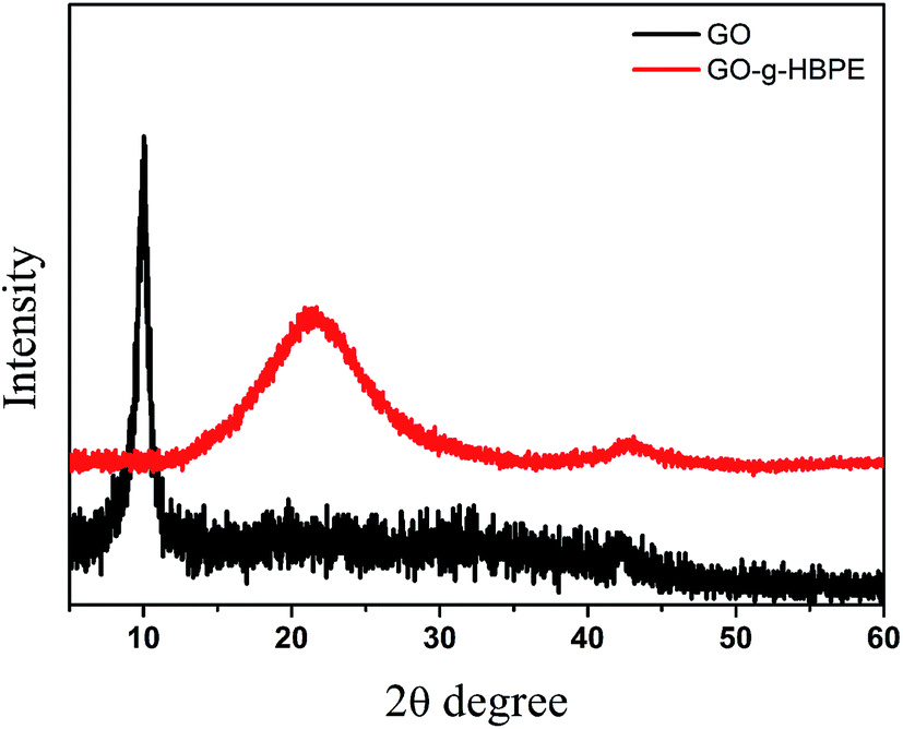 | ||
| Fig. 4 XRD patterns of GO and GO-g-HBPE. | ||
The thermal stability of GO and GO-g-HBPE was evaluated under a nitrogen atmosphere from 50 °C to 800 °C by TGA (Fig. 5a). A large weight loss (∼30%) occurs with an onset temperature of 200 °C, which means the GO is thermally unstable, due to the high concentration of water in GO and the thermal sensitive groups (epoxy, lactols and carbonyl) that disrupt the hexagonal carbon basal planes, resulting in a weakening of the van der Waals forces between layers.35,36 In contrast, no evidence for weight loss of GO-g-HBPE was observed before 200 °C. This suggests that the thermal stability is enhanced significantly by the introduction of HBPE polymer onto GO. This was attributed to the strong inter- and intra-molecular interactions. The thermal dimensional stability was determined further by the calculated dimensional changes after heating the separators to 200 °C for 0.5 h (see Fig. 5b and c). As shown in Fig. S5†, although the pure GO and MGO membranes have no evident dimensional changes, both can succumb to thermal decomposition, and this result corresponds to TGA. Fig. 5b and c show that the GO-g-HBPE separator shows superior thermal dimensional stability than the PP separator. This not only depends on the thermal robustness of the GO-g-HBPE, but also on the non-polymeric binder used in the membrane.
 | ||
| Fig. 5 (a) TGA curves of GO and GO-g-HBPE; photographs of the PP and GO-g-HBPE separators (b) before and (c) after heating to 200 °C for 0.5 h. | ||
The electrochemical stability was tested by linear sweep voltammetry at 5 mV s−1 to determine if the GO-g-HBPE separator was suitable for Li-ion batteries. As shown in Fig. S6,† the current flow of MGO separator was only steady before 4 V owing to electrochemical active groups, such as epoxy, lactols and carbonyl, benefitting from the stacked layer structure, and the pure GO separator showed a voltage-tolerance of 4.3 V, as shown in Fig. 6a. The current flow is increased significantly to 4.5 V for the PP separator, which indicates electrochemical decomposition. In the case of the GO-g-HBPE separator, no evidence of current flow was observed before 5 V. This indicates that the separator based on GO-g-HBPE exhibited superior electrochemical stability than the PP separator, resulting from the lower concentration of electrochemical active groups (epoxy, lactols and carbonyl).
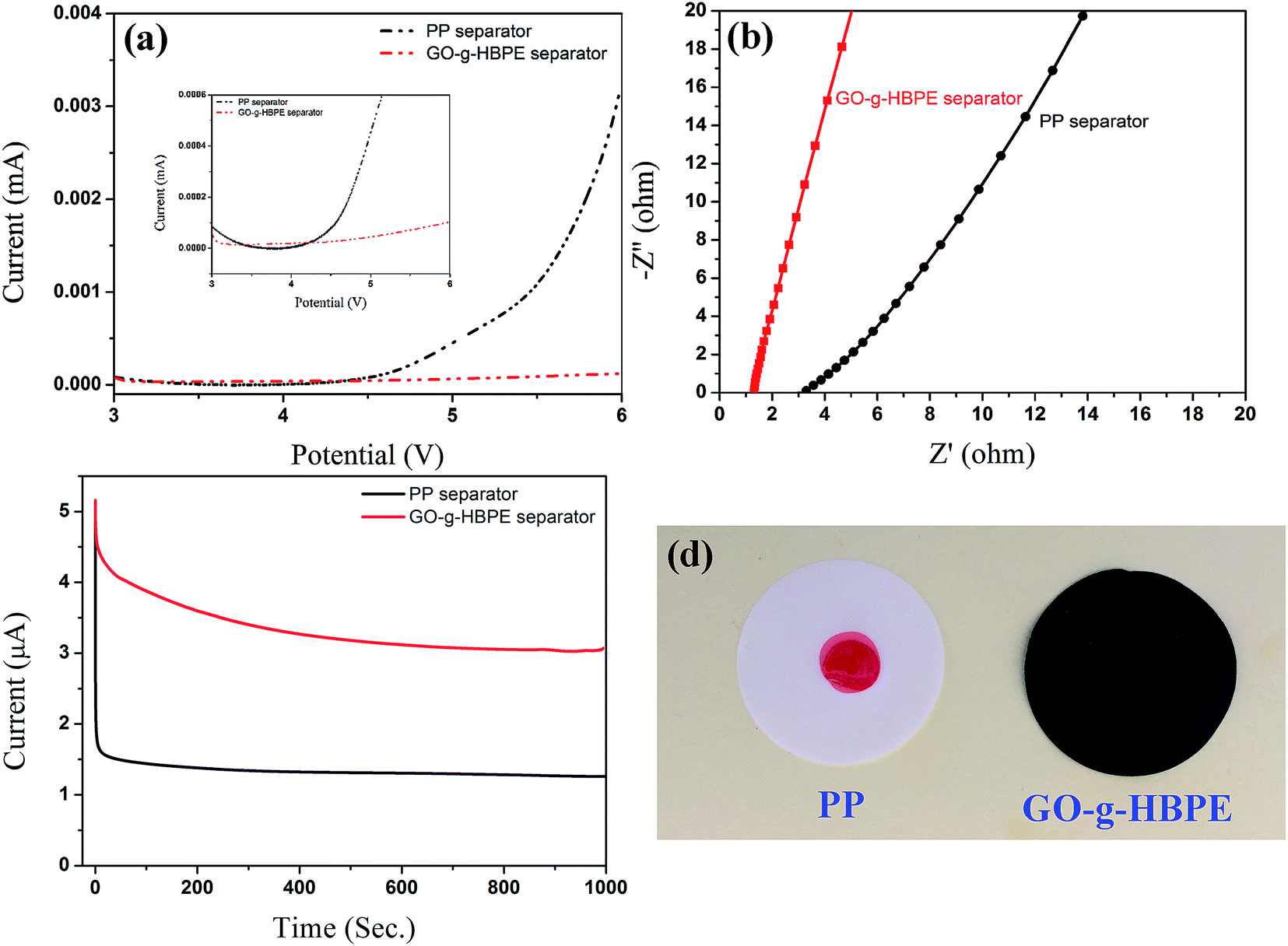 | ||
| Fig. 6 (a) Linear sweep voltammograms of PP and GO-g-HBPE separator; (b) AC impedance spectra of PP and GO-g-HBPE separator; (c) chronoamperometry profiles of the PP and GO-g-HBPE separator under a step potential of 10 mV; (d) photograph of electrolyte infiltration on the separator (the electrolyte contained methyl orange). | ||
In order to investigate the ionic conductivity of the separator based on PP and GO-g-HBPE, which determines the applicability of the separators for Li-ion batteries. A cell type of SS//separator//SS was used to evaluate Rb of both separators by the AC impedance. The calculated ionic conductivity for these separators was 0.47 mS cm−1 and 1.7 mS cm−1, which is much higher than that of the pure GO (0.07 mS cm−1) and MGO (0.28 mS cm−1) separator, as shown in Table S2† obtained from the value of Rb (Fig. 6b). This indicates that the GO-g-HBPE separator is suitable for high-power Li-ion batteries. Furthermore, the number of t+ was tested by chronoamperometry using Li foil as both electrodes. The specific t+ numbers for PP and GO-g-HBPE separators are 0.26 and 0.58, as obtained from the value of initial current to the equilibrium current in Fig. 6c. However, the t+ of pure GO and MGO separator was only 0.11 and 0.18, respectively. These remarkable ionic conductivities and relatively high t+ numbers are due mainly to the high porosity and superior liquid electrolyte uptake. The wetting characteristics of the electrolyte on the separators is shown in Fig. 6d. The electrolyte was formed dropwise on the PP separator but spread over the GO-g-HBPE separator. This suggests that the GO-g-HBPE has better electrolyte compatibility owing to the multi ether groups in the HBPE chain. The porosity and liquid electrolyte uptake of the separators can be observed in Table S2.† Although the porosity of MGO and GO-g-HBPE membrane are close (55% for MGO, 58% for GO-g-HBPE), the electrolyte uptake of GO-g-HBPE is much higher than that of MGO (68% for MGO; 158 for GO-g-HBPE). This suggests that the membrane of GO-g-HBPE is more suitable as a separator for Li-ion batteries than that of MGO. This is because the electrolyte uptake is determined by the membrane morphology and electrolyte absorptivity (swelling property). The macropores morphology provides volume to retain the electrolyte, and the electrolyte uptake of MGO and pure GO separator is well supported. On the other hand, the rigid hexagonal carbon skeleton is difficult to swell by the electrolyte. However, HBPE with a flexible polymer chain is easy swelling and the ether group assists in the retention of electrolyte, which causes the high electrolyte uptake of the GO-g-HBPE separator.
We investigated and discussed the electrochemical performance of the cells consisting of electrolyte-soaked PP and GO-g-HBPE separators sandwiched between two electrodes that used LiFePO4 as a cathode, lithium foil as a counter and reference electrode. Fig. 7a shows the first charge–discharge curves of the separators based on PP and GO-g-HBPE at 0.1C (25.50 mA g−1) in voltage range from 2.75 to 4.2 V. The typical electrochemical pseudoplateaus for LiFePO4 (3.5 V for charge, 3.4 V for discharge) can be observed in Fig. 7a. This depends on the oxidation and reduction potential for LiFePO4.37–39 The discharge capacity of GO-g-HBPE based on the separator is 160 mA h g−1, which is higher than 150 mA h g−1 for PP separator. Moreover, the polarization value for GO-g-HBPE separator (0.11 V), calculated from the difference in the charge and discharge plateaus, is lower than that of the PP separator (0.14 V). This indicates that the GO-g-HBPE separator exhibits lower internal resistance than the PP counterpart. The reasons are mainly the excellent liquid electrolyte uptake for GO-g-HBPE separator and its macro-porous structure, which provides high ionic conductivity and a larger t+ number than that of the PP counterpart. On the contrary, there is a valley at the end of the first discharge plateau and a peak at the beginning of the charge profile for the cell with the pure GO separator, which is an indication of a large polarization. The charge curve for the cell based on the MGO separator, as shown in the red arrow labeled in Fig. S7,† indicates poor electrochemical stability. This is because the stacked layer of the pure GO separator impedes the ionic transportation and makes it to be saturated by the liquid electrolyte, which further increases the polarization of the batteries. The electrochemical instability was attributed to the decomposition of electrochemical-active groups in GO. The result is consistent with the property of electrochemical stability of the MGO separator (Fig. S6†). The rate behavior for the cells employing the PP separator and GO-g-HBPE tested at various current densities (0.2C: 51.0 mA g−1, 0.5C: 127.5 mA g−1, 1C: 255.0 mA g−1, 2C: 510.0 mA g−1, 5C: 1275.0 mA g−1) is displayed in Fig. 7b. Fig. 7b shows that the discharge capacity of the cell using the PP separator decreases significantly from 143 mA g−1 at 0.2C to 70 mA g−1 at 5C; in the case of the GO-g-HBPE separator, the capacity is kept at 145 mA g−1 for 0.2C and 110 mA g−1 for 5C. The capacity retention for each is 48% and 76%, respectively. This suggests that the cell based on GO-g-HBPE separator shows good rate capability. To evaluate cycling stability of batteries for commercial applications, the cycling performance of the cells with both separators was measured on a LAND cycle system at 0.2C for 200 cycles. As shown in Fig. 7c, the cell assembled with the GO-g-HBPE separator showed better cycling stability and initial capacity than that of the cell using the PP separator. Moreover, the capacity retention after 200 cycles for the cell equipped with the GO-g-HBPE separator was 84% higher than the 47% for the cell based on the PP separator. The obtained results were attributed to a stable solid electrolyte interface layer (SEI). Furthermore, this stable SEI layer provides steady ionic transportation, resulting in good cycling performance.40 The variation of the cell impedance during cycling was confirmed by examining the resistance changes of the cell based on the both separators after the 1st and 100th cycles. The semicircle at the high frequency represents the charge transference resistance corresponding to migration of Li ions between the electrode and electrolyte interface; the straight slopping line is accompanied by the diffusion of Li ions in the active material of the electrode.41,42 Fig. 7d shows that the charge transference resistance after the 1st cycle of the cell using GO-g-HBPE separator was 90 ohm, which is slightly lower than that of the PP separator (120 ohm). The resistance after 100 cycles for the cell with the PP separator intensively increased to 500 ohm (380 ohm for difference of transference resistance), whereas that of the cell based on the GO-g-HBPE separator displayed 150 ohm (60 ohm for difference of transference resistance). This indicates that the GO-g-HBPE exhibits better interface stability than that of the PP separator, which is coincident with the cycling performance of the batteries. To simulate the actual working conditions of batteries, the cycling performance was further examined at an elevated temperature of 80 °C. As shown in Fig. 7e, the cell equipped with the GO-g-HBPE separator at 80 °C showed even better cycling performance than the one at room temperature. This is dependent on the viscosity of the electrolyte. The viscosity of the electrolyte decreases at elevated temperature and at this time, the Li+ ion passes rapidly from the macroporous GO-g-HBPE, leading to a high performance. In contrast, in the case of PP separator, the discharge capacity decreased significantly at serial cycles, and the performance was lost at 56 cycles. This means that the flexible PP polymer chain can be activated at high temperature, reflecting a high mobility. This could weaken the mechanical performance of the PP separator. In addition, dendritic lithium favors an accelerated electrochemical reaction, further causing the separator to be punctured.
 | ||
| Fig. 7 Electrochemical performance of the LiFePO4 half cells assembled with PP and GO-g-HBPE separators; lithium foil served as both the counter and reference electrodes: (a) the first charge–discharge curves; (b) rate behaviour; (c) cycling performance; (d) 1st and 100th cycle AC impedance spectra of the GO-g-HBPE separator (the inset provides the 1st- and 100th-cycle AC impedance spectra of the PP separator); (e) charge–discharge performance at an elevated temperature of 80 °C. | ||
4. Conclusions
In summary, a macro-porous GO-g-HBPE membrane serving as the separator for Li-ion battery was prepared by a vacuum filtration method, using PS nanoparticles as the hard template. To assist with the HBPE polymer segment, this separator shows excellent electrolyte uptake and ionic conductivity. Moreover, the separator exhibited remarkable thermal resistance after grafting HBPE. These show that the batteries using the GO-g-HBPE separator exhibit a much better rate capability, higher discharge capacity and superior capacity retention than the PP separator, highlighting the promising potential applications in high-safety and high-power lithium-ion batteries.Acknowledgements
This study is supported by the link project of the National Natural Science Foundation of China and Guangdong Province (No. U1401246), the National Natural Science Foundation of China (Grant No. 51276044), the Science and Technology Program of Guangdong Province of China (Grant No. 2014B010106005, 2015B010135011, 2015A050502047, 2016A020221031), Research Fund of Young Teachers for the Doctoral Program of Higher Education of China (20134420120009), Special Program for Public Interest Research and Capability Construction of Guangdong (2014A010105047), Science and Technology Planning Project of Guangzhou (201707010367) and the Science and Technology Program of Guangzhou City of China (Grant No. 201508030018).References
- P. Arora and Z. J. Zhang, Chem. Rev., 2004, 104, 4419–4462 CrossRef CAS PubMed.
- C. J. Orendorff, Electrochem. Soc. Interface, 2012, 21, 61–65 CrossRef CAS.
- S. H. Woo, H. W. Lim, S. Jeon, J. J. Travis, S. M. George, S. H. Lee and N. S. Choi, J. Electrochem. Soc., 2013, 160, A2234–A2243 CrossRef CAS.
- H. Li, Z. Wang, L. Chen and X. Huang, Adv. Mater., 2009, 21, 4593–4607 CrossRef CAS.
- H. Lee, M. Yanilmaz, O. Toprakci, K. Fu and X. Zhang, Energy Environ. Sci., 2014, 7, 3857–3886 CAS.
- Y. Hu and X. Sun, J. Mater. Chem. A, 2014, 2, 10712–10738 CAS.
- J.-W. Jung, C.-L. Lee, S. Yu and I.-D. Kim, J. Mater. Chem. A, 2016, 4, 703–750 CAS.
- C. J. Orendorff, T. N. Lambert and C. A. Chavez, Adv. Energy Mater., 2013, 3, 314–320 CrossRef CAS.
- X. C. Xiao, D. Ahn, Z. Y. Liu, J. H. Kim and P. Lu, Electrochem. Commun., 2013, 32, 31–34 CrossRef CAS.
- D. Fu, B. Luan, S. Argue, M. N. Bureau and I. J. Davidson, J. Power Sources, 2012, 206, 325–333 CrossRef CAS.
- P. G. Balakrishnan, R. Ramesh and T. P. Kumar, J. Power Sources, 2006, 155, 401–414 CrossRef CAS.
- J.-A. Choi, S. H. Kim and D.-W. Kim, J. Power Sources, 2010, 195, 6192–6196 CrossRef CAS.
- M.-H. Ryou, Y. M. Lee, J.-K. Park and J. W. Choi, Adv. Mater., 2011, 23, 3066–3070 CrossRef CAS PubMed.
- W.-K. Shin and D.-W. Kim, J. Power Sources, 2013, 226, 54–60 CrossRef CAS.
- J. C. Song, M. H. Ryou, B. Son, J. N. Lee, Y. M. Lee, J. W. Choi and J. K. Park, Electrochim. Acta, 2012, 85, 524–530 CrossRef CAS.
- J.-J. Woo, Z. Zhang, N. L. D. Rago, W. Lu and K. Amine, J. Mater. Chem. A, 2013, 1, 8538–8540 CAS.
- Y. Zhai, N. Wang, X. Mao, Y. Si, J. Yu, S. S. Al-Deyab, M. El-Newehy and B. Ding, J. Mater. Chem. A, 2014, 2, 14511–14518 CAS.
- J. Zhang, Z. Liu, Q. Kong, C. Zhang, S. Pang, L. Yue and G. Cui, ACS Appl. Mater. Interfaces, 2012, 5, 128–134 Search PubMed.
- T.-H. Cho, M. Tanaka, H. Ohnishi, Y. Kondo, M. Yoshikazu, T. Nakamura and T. Sakai, J. Power Sources, 2010, 195, 4272–4277 CrossRef CAS.
- M. Xiong, H. L. Tang, Y. D. Wang and M. Pan, Carbohydr. Polym., 2014, 101, 1140–1146 CrossRef CAS PubMed.
- M. Raja, N. Angulakshmi, S. Thomas, T. P. Kumar and A. M. Stephan, J. Membr. Sci., 2014, 471, 103–109 CrossRef CAS.
- Y. C. Jung, S. K. Kim, M. S. Kim, J. H. Lee, M. S. Han, D. H. Kim and D. W. Kim, J. Power Sources, 2015, 293, 675–683 CrossRef CAS.
- D. A. Dikin, S. Stankovich, E. J. Zimney, R. D. Piner, G. H. Dommett, G. Evmenenko and R. S. Ruoff, Nature, 2007, 448, 457–460 CrossRef CAS PubMed.
- D. C. Marcano, D. V. Kosynkin, J. M. Berlin, A. Siniskii, Z. Sun, A. Slesarev and J. M. Tour, ACS Nano, 2010, 4, 4806–4814 CrossRef CAS PubMed.
- A. Sunder, R. Hanselmann, H. Frey and R. Mülhaupt, Macromolecules, 1999, 32, 4240–4246 CrossRef CAS.
- J. Lee, C. K. Hong, S. Choe and S. E. Shim, J. Colloid Interface Sci., 2007, 310, 112–120 CrossRef CAS PubMed.
- H. Liao, H. Hong, H. Zhang and Z. Li, J. Membr. Sci., 2016, 498, 147–157 CrossRef CAS.
- J. Shi, Y. Xia, Z. Yuan, H. Hu, X. Li, H. Jiang and Z. Liu, J. Mater. Chem. A, 2015, 3, 7006–7013 CAS.
- D.-W. Wang, C. Sun, G. Zhou, F. Li, L. Wen, B. C. Donose and I. R. Gentle, J. Mater. Chem. A, 2013, 1, 3607–3612 CAS.
- Q. Zeng, X. Leng, K.-H. Wu, I. R. Gentle and D.-W. Wang, Carbon, 2015, 93, 611–619 CrossRef CAS.
- S. Stankovich, D. A. Dikin, R. D. Piner, K. A. Kohlhaas, A. Kleinhammes, Y. Jia and R. S. Ruoff, Carbon, 2007, 45, 1558–1565 CrossRef CAS.
- W. Cai, R. D. Piner, F. J. Stadermann, S. Park, M. A. Shaibat, Y. Ishii and J. An, Science, 2008, 321, 1815–1817 CrossRef CAS PubMed.
- W. Gao, L. B. Alemany, L. Ci and P. M. Ajayan, Nat. Chem., 2009, 1, 403–408 CrossRef CAS PubMed.
- K.-W. Park and J. H. Jung, J. Power Sources, 2012, 199, 379–385 CrossRef CAS.
- J. Shen, Y. Hu, M. Shi, X. Lu, C. Qin, C. Li and M. Ye, Chem. Mater., 2009, 21, 3514–3520 CrossRef CAS.
- E. Yoo, J. Kim, E. Hosono, H. Zhou, T. Kudo and I. Honma, Nano Lett., 2008, 8, 2277–2282 CrossRef CAS PubMed.
- J. Zhang, L. Yue, Q. Kong, Z. Liu, X. Zhou, C. Zhang and Y. Duan, Sci. Rep., 2014, 4, 3935 Search PubMed.
- A. Yamada, S. C. Chung and K. Hinokuma, J. Electrochem. Soc., 2001, 148, A224–A229 CrossRef CAS.
- C. Delmas, M. Maccario, L. Croguennec, F. L. Gras and F. Weill, Nat. Mater., 2008, 7, 665–671 CrossRef CAS PubMed.
- L. Pan, H. Wang, C. Wu, C. Liao and L. Li, ACS Appl. Mater. Interfaces, 2015, 7, 16003–16010 CAS.
- Q. J. Wang, W. L. Song, L. Z. Fan and Q. Shi, J. Power Sources, 2015, 279, 405–412 CrossRef CAS.
- S. Hu, S. Lin, Y. Tu, J. Hu, Y. Wu, G. Liu and T. Jiang, J. Mater. Chem. A, 2016, 4, 3513–3526 CAS.
Footnote |
| † Electronic supplementary information (ESI) available. See DOI: 10.1039/c7ra02950k |
| This journal is © The Royal Society of Chemistry 2017 |