
 Open Access Article
 This Open Access Article is licensed under a
 Creative Commons Attribution 3.0 Unported Licence
Three-dimensional N-doped carbon nanotube@carbon foam hybrid: an effective carrier of enzymes for glucose biosensors
Pinchao Fan,
Lijuan Liu,
Qiaohui Guo *,
Junli Wang,
Jinhua Yang,
Xiaoyu Guan,
Shuiliang Chen and
Haoqing Hou*
*,
Junli Wang,
Jinhua Yang,
Xiaoyu Guan,
Shuiliang Chen and
Haoqing Hou*
Department of Chemistry and Chemical Engineering, Jiangxi Normal University, Nanchang, Jiangxi 330022, China. E-mail: guoqiaohui@jxnu.edu.cn; Fax: +86-791-8812-0536; Tel: +86-791-8812-0389
First published on 17th May 2017
Abstract
Development of efficient, reliable, and cost-effective biosensors for accurate and convenient detection of glucose is highly desirable in the food industry, biotechnology, and clinical diagnosis. Carbon nanotube (CNT)-based enzyme biosensors have received considerable attention due to their excellent performance. However, the performance of these sensors is limited by the drawbacks of CNTs such as low electron transfer rate and catalytic area, and poor conductivity. Herein, three-dimensional (3D) nitrogen-doped CNTs (N-CNTs) supported by a carbon foam (N-CNT@CF) hybrid is fabricated as the carrier matrix to load glucose oxidase (GOD) for constructing high-performance glucose biosensors. A one-step chemical vapor deposition method is employed for the preparation of a N-CNT@CF hybrid, where N-CNTs are densely grown on the skeleton of carbon foam using iron as a catalyst. FT-IR spectroscopy shows that the N-CNT@CF is an effective carrier of GOD without enzyme denaturation. Combined with the extraordinary properties of 3D N-CNT@CF including large active surface area, high conductivity and fast mass transport dynamics, the GOD/N-CNT@CF biosensor achieves a large linear range (0.05–15.55 mM, R = 0.996) and a low detection limit (5.0 μM, S/N = 3) for the detection of glucose. Furthermore, the glucose biosensor exhibited high selectivity, good repeatability and stability.
1. Introduction
Carbon-based nanomaterials including carbon nanofibers,1 carbon nanotubes (CNTs),2,3 graphene,4,5 and graphene oxide6,7 have attracted much attention over the past decades. These novel carbon nanostructures, with superior electrical, physicochemical and electrochemical properties, have been extensively studied for the development of electrochemical electrodes for biosensing,8,9 energy storage,10,11 and conversion.12 Recently, in the area of enzyme-based electrochemical biosensing, nitrogen-doped CNTs (N-CNTs) have been widely studied for achieving the direct electron transfer (DET) of redox enzymes especially glucose oxidase (GOD), and their application in glucose biosensing. However, the electrodes prepared with CNTs are mostly planar in nature with electrical properties emerging only in one-dimensional directions. Additionally, poor electrical contact and close-packed structure of the individual components on the electrode result in difficulties in maintaining the large surface area and mass transfer within the CNT networks.To address this issue, some self-supported conductive scaffolds, including graphene,13 electrospun carbon nanofibers mats,14–16 carbon fiber cloth/paper17 are often used as substrate to form three-dimensional (3D) N-CNTs hybrids for biosensing. The enhanced specific surface area and high electrochemical activity of those 3D conductive networks were as expected as a superior material in achieving DET of redox enzymes, which is deeply embedded redox factor of the enzyme. More recently, many studies suggested that due to the good structural homogeneity, high internal porosity, excellent processability, and the high surface-to-volume ratio, carbon foam (CF) with 3D porous structure showed wide application in various aspects, such as supercapacitors,18 electrochemical sensors,19 and oxygen reduction reaction (ORR) catalysts.20 For example, Chen reported a porous nitrogen doped carbon foam for ORR catalyst.20 The nitrogen doped carbon foam with excellent resilience was made by direct pyrolysis of commercial melamine resin foam. The nitrogen doped carbon foam with a three-dimensional cellular network consisting of carbon microfiber with abundant micro- and mesopores, displaying excellent electrocatalytic activity and good durability for oxygen reduction.
Herein, we prepared a 3D N-CNTs supported by carbon foam (N-CNT@CF) hybrid nanostructures, in which N-CNTs networks are densely arrayed on the channel walls of the carbon foam via the C–C bond. Compared to previously reported N-CNT/carbon composites, the present N-CNT@CF hybrids exhibited many advantages. Firstly, different from the complex preparing processes and relatively high cost of electrospun nanofiber mats and carbon nanotube arrays, 3D carbon foam was prepared from low-cost melamine resin foam via direct pyrolysis process. Secondly, the pyrolysis of carbon substrate and the growth of N-CNTs were achieved in one-step process, which is more energy-saving and simpler than the traditional two-step methods. Thirdly, because of the presence of CF framework, the N-CNTs arrays are rarely stacked, ensuring many active sites for biomolecules immobilization. Finally, the coexistence of CF and conductive N-CNTs contributed to high conductivity, leading to fast electron transfer. The electrochemical results demonstrated that GOD molecules were efficiently immobilized on the surface of N-CNT@CF without denaturation, exhibiting good glucose biosensing performance.
2. Experimental
2.1 Chemicals and reagents
Melamine resin foam (MF) supplied by Puyang Green Universh Chemical Co., Ltd., glucose oxidase (GOD, EC 1.1.3.4, 108 U mg−1, from Aspergillus niger) and nafion (5 wt%) were obtained from Sigma. D-glucose, uric acid (UA), dopamine (DA) and ascorbic acid (AA) were purchased from Alfa Aesar. Other reagents were of analytical grade and were used without further purification. Phosphate buffer saline (0.1 M PBS) was prepared by mixing 0.1 M NaH2PO4 and 0.1 M Na2HPO4. All aqueous solutions were prepared with deionized distilled water obtained from a Milli-Q water-purifying system (18 MΩ cm).2.2 Apparatus
Morphological characterization was performed on a TESCAN VEGA-3 scanning electron microscope (SEM). The microstructure was characterized by X-ray diffraction (XRD, Bruker D8 Advance diffractometer) equipped with Cu Kα radiation at 40 kV and 30 mA in reflection mode. The composition was characterized by Raman spectrum (HORIBA JOBIN VON) and X-ray photoelectron spectrum (XPS, PHI Quantera). The XPS data were collected using a dual anode X-ray source with Mg K radiation at an energy of 1253.6 eV. Fourier transform infrared (FT-IR) measurements were performed on a Bruker EQUINOX 55 duroscope. All spectra were collected using 16 scans in the range from 4000 to 600 cm−1 with a 4 cm−1 spectral resolution and a 5s acquisition time for each spectrum. N2 adsorption/desorption isotherms were measured at −196 °C using an ASAP 2020 instrument (Micromeritics). Before the experiment, the samples were degassed under vacuum at 120 °C. The surface area was calculated using the BET equation. The pore-size distribution was calculated by the Barrett–Joyner–Halenda (BJH) method. All electrochemical experiments were performed on a CHI 760E electrochemical workstation (Shanghai, China). A three-electrode configuration was used with a platinum wire as the auxiliary electrode, a Ag/AgCl (saturated KCl) as the reference electrode, and the bare glass carbon electrode (GC) or modified GC electrode as the working electrode.2.3 Preparation of N-CNT@CF hybrids
N-CNT@CF hybrids were synthesized by a CVD process using melamine resin foam (MF) as a template21 as shown in Scheme 1. In a typical experiment, MF was cut into pieces and dipped into 1 mM Fe(OH)3 sol solution for 12 h, then dried at 60 °C to get catalyst precursor-loaded MF. N-CNT@CF was prepared in a quartz tube via a CVD process: firstly, heating up to 500 °C at a rate of 5 °C min−1 and staying for 0.5 h under N2 atmosphere; further heating up to 700, 800, and 900 °C in N2 at a rate of 5 °C min−1 for 0.5 h, then pyridine was injected into the quartz tube (0.1 mL min−1) via a syringe for N-CNTs growth. The mass flow of N2 and H2 were controlled at 150 sccm and 60 sccm during N-CNTs formation. After a 20 min growth, the H2 was switched to N2 with the same flow rate and the furnace was cool down to room temperature. | ||
| Scheme 1 Schematic illustration for the preparation of N-CNT@CF hybrids. | ||
2.4 Electrode preparation
GC (Φ = 3 mm) was polished carefully using Al2O3 powder. The electrode was rinsed and sonicated twice with the distilled water and used for further experiments after drying. 10 mg mL−1 N-CNT@CF was dispersed in a solvent mixture containing 25 μL of Nafion (5 wt%) and 250 μL of ultra-pure water using sonication. Immediately after dispersion, 3 μL of N-CNT@CF slurry was coated onto GC electrode surface (N-CNT@CF/GC), and dried at 25 °C for 24 h. Prior to use, the N-CNT@CF modified electrode was cycled in PBS solution (from −0.8 to 0.4 V vs. Ag/AgCl, about 100 times at 300 mV s−1) in order to passivate residual electroactive iron remaining from synthesis.22 Then 5 μL of GOD solution (5 mg mL−1) was coated onto N-CNT@CF electrode (GOD/N-CN@CF) and dried at 4 °C for 24 h. Finally, the modified electrode was rinsed by ultra-pure water to remove weakly bound molecules and was stored at 4 °C for further use.3. Results and discussion
3.1 Characterizations of N-CNT@CF
The synthetic process of 3D N-CNTs@CF composites was shown in Scheme 1. Melamine resin foam (MF) was first immersed into Fe(OH)3 solution for catalyst precursor adsorption. After drying, carbonization of MF into carbon foam (CF) and the in situ growth of N-CNTs can be simultaneously achieved through a CVD process by using pyridine as carbon- and nitrogen-containing precursor. Typical SEM images suggested that CF showed a well-defined macroporous network architecture with pore diameter about 100–200 μm, and the diameter of CFs range from 3 to 5 μm (Fig. 1A and B). After the catalyst precursor adsorption process, it could be seen that amounts of Fe nanoparticles were uniformly dispersed on the surface of CF (Fig. 1C and D). Such a uniform catalyst dispersion is favorable for the homogeneous growth of N-CNTs. | ||
| Fig. 1 SEM images of MF (A and B) and Fe@CF (C and D), respectively. | ||
Iron-group metals are considered the most effective catalysts for the growth of CNTs via CVD.23 After the simple CVD process, 3D porous CF with surface covered by a uniform layer of N-CNTs has been successfully synthesized. Catalyst precursor of Fe nanoparticles were decomposed into oxides and further reduced to metal nanoparticles through the carbothermic reduction process. In the following CVD process, pyridine was decomposed into amines and carbon species which functioned as nitrogen and carbon source. The SEM images of the N-CNT@CF hybrids prepared from different growth temperature are shown in Fig. 2, curved NCNTs with length of several micrometers are uniformly distribute onto the surface of carbon form, forming a quasi-aligned N-CNTs array. Furthermore, it can be seen that small N-CNTs (less than 30 nm) were produced and only part of the CF was covered by N-CNTs at 700 °C (Fig. 2A–C). When the growth temperature was reached to 800 °C, the skeleton of CF was fully covered by high-density N-CNTs with diameter of about 70 nm (Fig. 2D–F). However, further increasing the growth temperature to 900 °C, longer (a few micrometer) but lower density of N-CNTs were growed on CF (Fig. 2G–I). Those results were similar to the previous report.15 The control experiments indicated that Tc = 800 °C was the best temperature among the three studied temperature. Therefore, in the following studies, Tc = 800 °C was selected for synthesizing 3D N-CNT@CF hybrid.
 | ||
| Fig. 2 SEM images of N-CNT@CF at different growth temperature and the corresponding diameter-distribution histograms, (A–C) 700 °C, (D–F) 800 °C and (G–I) 900 °C, respectively. | ||
To probe the chemical composition in N-CNT@CF hybrid, XPS measurements were performed. The survey XPS spectrum of N-CNT@CF reveals the presence of C, O, Fe, and N elements (Fig. 3A). The N 1s spectrum is very useful for analyzing the property of N functionalities. Three N species were present in N-CNT@CF, including pyridinic-N (397.9 eV), pyrrolic-N (400.0 eV) and graphitic-N (401.2 eV) (Fig. 3B). The relative amount of three N species is 66.8, 9.4, and 22.8% for pyridinic-N, pyrrolic-N and graphitic-N, respectively. Among them, pyridinic-N refers to the nitrogen atom on the edge of graphite planes with two adjacent carbon, and graphite-N represents the nitrogen atom bonded to three carbon atoms with in a graphite plane, while pyrrolic-N refers to nitrogen atom that contribute to the system with two p electrons.24 The pyridinic-N was believed to provide the effective electron to enhance the catalytic performance.25
 | ||
| Fig. 3 XPS (A), high-resolution N 1s XPS (B), Raman (C) spectra of N-CNT@CF hybrid; (D) nitrogen adsorption–desorption isotherms of N-CNT@CF. Inset: pore size distribution calculated from BJH method. | ||
Raman spectroscopy provided further information of the N-doping effect in the N-CNT@CF (Fig. 3C). The peak of 1336 cm−1 is referred to D-band and the other one locates at 1598 cm−1 is referred to G-band. The intensity ratio of the D- to G-band (ID/IG) reflects the degree of disorder in N-CNT@CF. The results suggested that the ID/IG ratios were 1.02 and 0.89 for Fe@CF and N-CNT@CF, respectively, indicating more defects and edge planes in N-CNT@CF, caused by the heterogeneous nitrogen-atom doping onto the graphite layers of CNTs.26
The nitrogen adsorption/desorption isotherm curves demonstrated type-IV isotherm (Fig. 3D), which has a sharp capillary condensation step at relative high pressure, implying the presence of porous structure and a narrow distribution of pore size. The specific surface area of N-CNT@CF was 215.2 m2 g−1. The pore size distribution was calculated by the BJH method (insert of Fig. 3D). It can be seen that the pore diameter of N-CNT@CF sample was mainly distributed at around 8–10 nm with large pore volume, roughly matching the dimension of GOD molecules (7.0 nm × 5.5 nm × 8.0 nm).25 The high surface area and a uniform pore distribution provided abundant active sites for the immobilization of enzyme, hence the 3D N-CNT@CF composite was expected to be an idea material in the detection of electroactive species.
Taking the advantages of large surface area with pores at around 10 nm and 3D network nanostructure, N-CNT@CF can serve as a carrier matrix for efficient enzyme immobilization and sensing. To demonstrate the practical utility, GOD was chosen as a model to evaluate the analytical performance of N-CNT@CF for the development of glucose biosensors. Fourier transform infrared (FT-IR) spectrum was used to investigate the structural changes of GOD after it was immobilized on N-CNT@CF (Fig. 4A). The free GOD exhibit two characteristic peaks at 1643 and 1533 cm−1, corresponding to the typical amide I and amide II adsorption bands of proteins.27 The signal peak at 1067 cm−1 was attributed to the C–O bond stretching vibration of GOD.28 The presence of both amide I and II adsorption peaks in the spectrum of GOD/N-CNT@CF indicated that the GOD biomolecules were successfully immobilized on the N-CNT@CF surface.
 | ||
| Fig. 4 FT-IR (A) and deconvoluted spectra of free GOD (B). (C) Comparison of the second structure component obtained from the value of amide I band. (D) CV curves of GOD/GC (a), GOD/Fe@CF/GC (b), and GOD/N-CNT@CF/GC (c) electrodes in 0.1 M N2-saturated PBS (pH 7.0) at a scan rate of 50 mV s−1, respectively. | ||
Furthermore, FT-IR spectrum is also considered as one of the most useful tools to investigate the secondary structure of proteins and monitor the enzyme activity. Herein, enzyme structure was determined by curve fitting the amide I band (1580–1700 cm−1) into its respective secondary structure components. The deconvolution of the amide I band for free GOD yields several distinct lorentzian peaks (Fig. 4B). The three bands at 1623, 1635 and 1685 cm−1 can be assigned to β-sheet structures with the 1685 cm−1 band characteristic of anti-parallel β-sheet structure.29 According to deconvolution results, the β-sheet contribution constitutes 46% of the second structures in free GOD. The band around 1659 cm−1 is characteristic of α-helix structure, and the area of this component accounts for 13% of the total band area. The random structure (28%) and β-turn (12%) contribute to the bands at 1647 and 1672 cm−1, respectively. The predominance of β-sheet contribution is in agreement with previous reports.30 When the same deconvolution procedure is applied to the amide I band in the spectrum of GOD/N-CNT@CF, it is evident that β-sheet content is still dominant although decreased in comparison to the case of free GOD, the random coil contribution is decreased in a significant way (Fig. 4C). A constant contribution from α-helix is related to a still active enzyme that has undergone no denaturation process.31 The results indicated that the enzymatic activity of GOD was preserved and a predominant β-sheet subcomponent was retained for GOD adsorbed on the N-CNT@CF surface.
3.2 Electrochemical performance of GOD/N-CNT@CF
The electrochemical performance of GOD/N-CNT@CF in N2-saturated 0.1 M PBS (pH 7.0) was investigated (Fig. 4D). As expected, there were no redox peaks appearing for the GOD/GC and GOD/Fe@CF electrodes (curves a and b). When the N-CNT@CF/GC was modified with GOD, a pair of stable and well-defined redox peak was observed (curve c). The anodic and cathodic peak potentials were located at −0.418 and −0.468 V, respectively. The small peak-to-peak separation (ΔEp = 50 mV) infers a fast redox of FAD/FADH2 at N-CNT@CF. The results indicated that the N-CNT@CF with good conductive framework could act as matrix for stable loading of GOD, and then as electron transfer tunel for effective connecting the active sites of GOD to the conductive sites.The surface coverage (Γ) of GOD in N-CNT@CF was estimated according to Γ = Q/nFA, where Q is the charge involved in the reaction, n is the number of electron transfer (n = 2), F is the Faraday constant, and A is the electrode area. The Γ value was estimated to be 9.2 × 10⁻¹⁰, which was much higher than those of 7.52 × 10⁻¹⁰ mol cm−2 at CNx-MWCNT modified GC electrode,32 5.88 × 10⁻¹⁰ mol cm−2 at MWCNTs modified GC electrode,33 and 2.86 × 10⁻¹² mol cm−2 at the bare electrode GC electrode,34 indicating that a multilayer and 3D coverage of GOD have been formed on N-CNT@CF. Such superior enzyme loading capability of N-CNT@CF might be attributed to the large surface area and pore volume of N-CNT@CF as well as the strong adsorption between GOD and N-CNT@CF.
Fig. 5 displayed the current response of GOD/N-CNT@CF modified electrode at different scan rates. Both the cathodic and anodic peak currents increased linearly with increasing scan rate, indicating a surface-controlled process. Additionally, the peak potential for the catalytic oxidation of glucose shifted to more positive values with the increasement of scan rate, suggesting a kinetic limitation in the reaction between the redox sites of GOD and N-CNT@CF hybrid.
 | ||
| Fig. 5 (A) CVs of GOD/N-CNT@CF/GC in 0.1 M pH 7.0 N2-saturated PBS solution at different scan rates (from 50 to 450 mV s−1, inside to outside). (B) Plots of peak current versus scan rate. | ||
3.3 Electrocatalytic behavior of GOD/N-CNT@CF
The influence of pH value was also investigated. As shown in Fig. 6, the electrochemical response of GOD/N-CNT@CF demonstrated strong dependence on solution pH value. Both anodic and cathodic peak potentials shifted negatively with increasing in the solution pH (Fig. 6A), indicating that proton was involved in the quasi-reversible reaction of FAD/FADH2. The pH value was also affected the peak current, which increased in the pH value until a maximum value reached at pH 7.0. Further increased the pH value leaded to a reduction in the peak current (Fig. 6B), possibly because the GOD immobilized on N-CNT@CF has higher bioactivity at a neutral pH. Therefore, further experiments were conducted in pH 7.0 PBS solution. The formal potential (Eθ) exhibited a linear relationship with the pH, and the slope was calculated to be 57.2 mV per pH (Fig. 6C). This slope was very close to the theoretical value of 59.0 mV per pH, indicating that two protons and two electrons were involved in the electron transfer process. | ||
| Fig. 6 (A) CVs of GOD/N-CNT@CF/GC in 0.1 M N2-saturated PBS solution with different pH values. Scan rate: 50 mV s−1. (B) Plots of peak current versus pH. (C) Plot of formal potential versus pH. (D) CVs of GOD/N-CNT@CF/GC in 0.1 M O2-saturated PBS (pH 7.0) containing various concentrations of glucose. | ||
The electrocatalytic behavior of the as-prepared biosensor on glucose oxidation was evaluated by CV in 0.1 M O2-saturated PBS (pH 7.0), the reduction peak currents at GOD/N-CNT@CF/GC electrode decreased gradually with the increase of glucose concentration (Fig. 6D). This is because the decrease of GOD (FAD) consumed by enzyme-catalyzed reaction restrained the electrochemical reaction, leading to the decrease of reduction current. Based on these, the GOD/N-CNT@CF/GC could serve as a glucose biosensor.
3.4 Glucose sensing performance of GOD/N-CNT@CF
When an aliquot of glucose was added to the stirred PBS solution, an obvious increase response current was observed (Fig. 7A). The as-prepared biosensor could reach the 95% steady-state current within 6 s, suggesting a rapid amperometric response behavior. The linear equation of the biosensor was y (μA) = 1.121x (mM) + 3.16, and the linear range was 0.05–15.55 mM (R = 0.996), which was larger than that of GOD/MWCNTs-chitosan (1.0–10.0 mM),35 GOD-NCNT@CNFs (0.1–12.5 mM),15 Nafion-mesocellular graphene foam-GOD/GCE (1.0–12.0 mM) 36, and ERGO–MWCNT/GOD/Nf electrode (0.01–6.5 mM).37 Moreover, the detection of limit (LOD) was 5.0 μM (S/N = 3), which was practicable for the determination of human blood sugar concentration (4.4–6.6 mM). According to the slope of the linear equation (1.121 μA mM−1) and the electrode area (0.07065 cm2), the sensitivity of the as-fabricated biosensor was calculated to be 15.87 μA mM−1 cm−2, which was also better than those of glucose biosensor based on Nafion-GOD-SWCNHs (3.53 μA mM−1 cm−2),38 CS/GOD/CNT (8.5 μA mM−1 cm−2)33 and ERGO–MWCNT/GOD/Nf electrodes (7.95 μA mM−1 cm−2).37 All the results indicated a good electrocatalytic activity and fast electron exchange behavior of the fabricated biosensor. The as-prepared biosensor presents superior performance, which can be attributed to the extraordinary properties of 3D N-CNT@CF including reasonable N doping for high enzyme loading, compatible microenvironment for maintaining its bioactivity, and the specific surface area and high conductivity for reactant and electron transport. | ||
| Fig. 7 (A) Current–time curve of GOD/N-CNT@CF/GC for successive addition of different concentrations to stirred 0.1 M O2-saturated PBS (pH 7.0) at −0.45 V. (B) Calibration curve of GOD/N-CNT@CF/GC for glucose. | ||
3.5 Analysis of real samples
In order to verify the reliability of the proposed method, the biosensor was further applied to determine the glucose content in human blood serum samples using a calibration curve and standard addition method. The human serum samples were received from Nanchang People's Hospital without any pretreatment. The recovery was 96.9–100.7% with relative standard deviation (RSD) less than 3.25%. Meanwhile, the content of glucose measured by the proposed method was in good agreement with the data provided by hospital, suggesting the strong applicability to real samples (Table 1).3.6 Selectivity, stability and reproducibility of the glucose biosensor
Oxidizable compounds such as ascorbic acid (AA), uric acid (UA), dopamine (DA) and some carbohydrates (e.g. maltose, xylose, mannose and lactose) are common electrochemical interfering species, which can coexist with glucose in real blood samples. The results indicated that the current responses were 0.32%, 0.17%, 0.37%, 0.23%, 0.08%, 0.06% and 0.19% for maltose, mannose, xylose, lactose, AA, DA and UA in contrast to glucose, respectively (Fig. 8). Hence, a highly selective response to glucose was obtained without the use of a perm-selective membrane.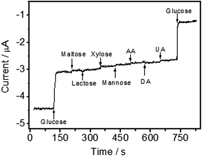 | ||
| Fig. 8 Interference test of GOD/N-CNT@CF/GC modified electrode in 0.1 M O2-saturated PBS (pH 7.0) at −0.45 V with 1.0 mM glucose and other interferents including 0.5 mM maltose, 0.5 mM lactose, 0.5 mM xylose, 0.5 mM mannose, 0.5 mM AA, 0.5 mM DA, and 0.5 mM UA. | ||
Reproducibility and stability are important parameters to evaluate the applicability of electrochemical sensors. Herein, the batch-to-batch reproducibility of the GOD/N-CNT@CF/GC was estimated from the current responses of six different electrodes to 3.0 mM glucose. The RSD was calculated to be 3.58%. In addition, the GOD/N-CNT@CF/GC electrode showed a RSD of 3.28% for six successive measurements of 5.0 mM glucose. When the electrode was stored at 4 °C for 3 weeks, the fabricated biosensor remained 91.2% of its bioactivity. These results indicated that the immobilized GOD retains its high enzymatic activity.
4. Conclusions
In summary, we report a facile method to prepare 3D N-CNTs to immobilize GOD and fabricate glucose sensing. Direct GOD electrochemistry and sensitive glucose sensing were simply achieved by immobilize GOD on N-CNT@CF hybrid. Due to the high conductivity, large surface area and pore volume, N-CNT@CF was beneficial to the high loading of electrocatalytic active GOD and the fast electron transfer. As a result, N-CNT@CF was used to fabricate glucose biosensor without any complicate modification, and this biosensor exhibited stable analytical performance and sensitive detection of glucose with a linear range from 0.05 to 15.55 mM. Our work suggested that the N-CNT@CF hybrid could be a suitable platform for the construction of high-performance glucose biosensing.List of abbreviations
| CNTs | Carbon nanotube |
| N-CNTs | Nitrogen-doped CNTs |
| GOD | Glucose oxidase |
| CF | Carbon foam |
| ORR | Oxygen reduction reaction |
| UA | Uric acid |
| DA | Dopamine |
| AA | Ascorbic acid |
| ΔEp | Peak-to-peak separation |
| Γ | Surface coverage |
| Eθ | Formal potential |
| ERGO–MWCNT/GOD/Nf | Electrochemically reduced graphene oxide/multiwalled carbon nanotubes/glucose oxidase/nafion |
| Nafion/GOD/SWCNHs | Nafion/glucose oxidase/single-walled carbon nanotubes |
| RSD | Relative standard deviation |
Acknowledgements
We are grateful for the National Natural Science Foundation of China (Grants No. 21405065) and the Science and Technology Project of Jiangxi Province (20161BCB24005).Notes and references
- C. Yang, M. E. Denno, P. Pyakurel and B. J. Venton, Anal. Chim. Acta, 2015, 887, 17–37 CrossRef CAS PubMed.
- M. L. Yola and N. Atar, Electrochim. Acta, 2014, 119, 24–31 CrossRef CAS.
- M. L. Yola, T. Eren and N. Atar, Biosens. Bioelectron., 2014, 60, 277–285 CrossRef CAS PubMed.
- A. T. Çolak, T. Eren and M. L. Yola, J. Electrochem. Soc., 2016, 163, F1237–F1244 CrossRef.
- M. L. Yola and N. Atar, J. Electrochem. Soc., 2016, 163, B718–B725 CrossRef CAS.
- M. L. Yola, T. Eren and N. Atar, Electrochim. Acta, 2014, 125, 38–47 CrossRef CAS.
- M. L. Yola, T. Eren and T. Atar, Sens. Actuators, B, 2015, 210, 149–157 CrossRef CAS.
- M. L. Yola, V. K. Gupta and T. Atar, Mater. Sci. Eng., C, 2016, 61, 368–375 CrossRef CAS PubMed.
- Q. H. Guo, D. Liu, X. P. Zhang, L. B. Li, H. Q. Hou, O. Niwa and T. Y. You, Anal. Chem., 2014, 86, 5898–5905 CrossRef CAS PubMed.
- D. Liu, Q. H. Guo, H. Q. Hou, O. Niwa and T. Y. You, ACS Catal., 2014, 4, 1825–1829 CrossRef CAS.
- M. L. Yola, T. Eren and T. Atar, Electroanalysis, 2016, 28, 570–579 CrossRef CAS.
- N. Atar, M. L. Yola and T. Eren, Appl. Surf. Sci., 2016, 362, 315–322 CrossRef CAS.
- X. Li, X. B. Zang, Z. Li, X. M. Li, P. X. Li, P. Z. Sun, X. Lee, R. J. Zhang, Z. H. Huang, K. L. Wang, D. H. Wu, F. Y. Kang and H. W. Zhu, Adv. Funct. Mater., 2013, 23, 4862–4869 CAS.
- S. J. He, L. L. Chen, C. C. Xie, H. Hu, S. L. Chen, M. Hanif and H. Q. Hou, J. Power Sources, 2013, 243, 880–886 CrossRef CAS.
- M. Zhang, G. Y. Zhou, Y. Feng, T. R. Xiong, H. Q. Hou and Q. H. Guo, Sens. Actuators, B, 2016, 222, 829–838 CrossRef CAS.
- Q. H. Guo, D. Zhao, S. W. Liu, S. L. Chen, M. Hanif and H. Q. Hou, Electrochim. Acta, 2014, 138, 318–324 CrossRef CAS.
- G. M. Wang, H. Y. Wang, X. H. Lu, Y. C. Ling, M. H. Yu, T. Zhai, Y. X. Tong and Y. Li, Adv. Mater., 2014, 26, 2676–2682 CrossRef CAS PubMed.
- H. Hu, S. Liu, M. Hanif, S. Chen and H. Hou, J. Power Sources, 2014, 268, 451–458 CrossRef CAS.
- S. He and W. Chen, J. Power Sources, 2014, 262, 391–400 CrossRef CAS.
- H. Zhang, Y. Zhou, C. G. Li, S. L. Chen, L. Liu, S. W. Liu, H. M. Yao and H. Q. Hou, Carbon, 2015, 95, 388–395 CrossRef CAS.
- S. J. He, H. Q. Hou and W. Chen, J. Power Sources, 2015, 280, 678–686 CrossRef CAS.
- J. Lyon and K. Stevenson, Langmuir, 2007, 23, 11311–11318 CrossRef CAS PubMed.
- R. Andrews, D. Jacques, D. L. Qian and T. Rantell, Acc. Chem. Res., 2002, 35, 1008–1017 CrossRef CAS PubMed.
- H. J. Zhang, H. L. Li, X. T. Li, B. Zhao, Z. F. Ma and J. H. Yang, Electrochim. Acta, 2014, 115, 1–9 CrossRef CAS.
- M. Vikkisk, I. Kruusenberg, U. Joost, E. Shulga and K. Tammeveski, Electrochim. Acta, 2013, 87, 709–716 CrossRef CAS.
- S. Maldonado and K. Stevenson, J. Phys. Chem. B, 2005, 109, 4707–4716 CrossRef CAS PubMed.
- S. Wu, H. X. Ju and Y. Liu, Adv. Funct. Mater., 2007, 17, 585–592 CrossRef CAS.
- S. J. Bao, C. Li, J. F. Zang, X. Q. Cui, Y. Qiao and J. Guo, Adv. Funct. Mater., 2008, 18, 591–599 CrossRef CAS.
- S. Krimm and J. Bandekar, Adv. Protein Chem., 1986, 38, 181–186 CrossRef CAS PubMed.
- H. J. Hecht, H. M. Kalisz, J. Hendle, R. D. Schmidt and D. J. Schomburg, J. Mol. Biol., 1993, 229, 153–158 CrossRef CAS PubMed.
- M. Portaccio, M. Lepore, B. Della-Ventura and D. G. Mita, J. Sol-Gel Sci. Technol., 2009, 50, 437–442 CrossRef CAS.
- S. Deng, G. Jian, J. Lei, Z. Hu and H. Ju, Biosens. Bioelectron., 2009, 25, 373–377 CrossRef CAS PubMed.
- X. Luo, A. Killard and M. Smyth, Electroanalysis, 2006, 18, 1131–1134 CrossRef CAS.
- J. Zhang, M. Feng and H. Tachikawa, Biosens. Bioelectron., 2007, 23, 438–442 CrossRef PubMed.
- C. Yang, C. Xu and X. Wang, Langmuir, 2012, 28, 4580–4585 CrossRef CAS PubMed.
- Y. Wang, H. X. Li and J. L. Kong, Sens. Actuators, B, 2014, 193, 708–714 CrossRef CAS.
- V. Mani, B. Devadas and S. M. Chen, Biosens. Bioelectron., 2013, 41, 309–315 CrossRef CAS PubMed.
- X. Q. Liu, L. H. Shi, W. X. Niu, H. J. Li and G. B. Xu, Biosens. Bioelectron., 2008, 23, 1887–1890 CrossRef CAS PubMed.
| This journal is © The Royal Society of Chemistry 2017 |