
 Open Access Article
 This Open Access Article is licensed under a Creative Commons Attribution-Non Commercial 3.0 Unported Licence
Modification of a Pd-loaded electrode with a carbon nanotubes–polypyrrole interlayer and its dechlorination performance for 2,3-dichlorophenol†
Zhirong Sun *a,
Ge Songa,
Ran Dua and
Xiang Hu*b
*a,
Ge Songa,
Ran Dua and
Xiang Hu*b
aNational Engineering Laboratory for Advanced Municipal Wastewater Treatment and Reuse Technology, Beijing University of Technology, Beijing 100124, P. R. China. E-mail: zrsun@bjut.edu.cn
bCollege of Chemical Engineering, Beijing University of Chemical Technology, Beijing 100029, P. R. China. E-mail: huxiang99@163.com
First published on 20th April 2017
Abstract
A novel Pd loaded Ti electrode was prepared with a carbon nanotubes and polypyrrole interlayer modification, referred to as a Pd/CNTs–PPy/Ti electrode. Pretreated CNTs were deposited on the substrate uniformly by electrophoretic deposition technique. Modification by the CNTs–PPy interlayer made the Pd particles smaller and well-distributed. Pulsed-current electrodeposition technique led to more compact Pd particles. The hydrogen adsorption current value increased 55.3% and the electrochemical active surface area (EASA) increased 58.7% compared to the electrode without modification. The prepared Pd/CNTs–PPy/Ti electrode was employed in dechlorination of 2,3-dichlorophenol (2,3-DCP) in aqueous solution. The potential impact factors on the electrocatalytic dechlorination were studied, including dechlorination current, initial pH value of catholyte, reaction temperature and common ions in aqueous solution. Complete dechlorination could be achieved within 70 min under the selected conditions i.e., current of 5 mA, and an initial pH of 2.5 at ambient temperature. The common ions in aqueous solution, such as NO3−, CO32−, HCO3−, Mg2+, K+ and Ca2+, had no obvious effect on the electrocatalytic dechlorination within the scope of this investigation. The prepared Pd/CNTs–PPy/Ti electrode exhibited promising dechlorination potential with higher electrochemical activity.
1. Introduction
Chlorophenols (CPs), typical persistent organic pollutants (POPs), are widely used as raw materials in the production of wood preservatives and pesticides,1–3 and have been listed as priority pollutants by the United States Environmental Protection Agency (USEPA).4,5 They are highly toxic and resistant to biodegradation. They not only impact ecological security, but also threaten the life and health of human beings. Therefore, the degradation of CPs is of great significance.There are several methods for CP removal, including biodegradation,6 chemical reduction,7,8 and electrocatalytic hydrogenolysis (ECH).9–11 ECH is considered an environmentally-friendly and highly-efficient technology in the dechlorination of CPs. Active hydrogen (H*) is generated during the ECH process. H* attacks CPs molecules chemisorbed on the electrode surface, leading to the dechlorination of CPs.12,13
Palladium (Pd) is usually used as catalyst in ECH process due to its strong ability in adsorption14,15 and absorption of hydrogen to form hydride.16,17 Many researchers attempted to develop methods for improving the electrocatalytic performance of the electrode, such as changing the substrate of the catalytic electrode or modifying the electrode by special materials. Polypyrrole (PPy), a typical conductive polymer with high electrical conductivity and chemical stability, can be used as support material to obtain highly dispersed metallic particles.18,19 In our previous studies,20–23 PPy modified composite Pd electrodes shown higher electrochemical activity for CPs dechlorination, indicating the PPy was conducive to Pd particles deposition dispersedly, and it can also play co-catalysis role.
Carbon nanotubes (CNTs) have received increasing attention since they were discovered in 1991.24 CNTs exhibit good electric conductivity, large specific surface area and high energy density capacity, and have been regarded as an ideal catalyst support material.25,26 CNTs have been used as Pd/Fe supporter for catalytic dechlorination of chlorinated organic compounds and complete removal of 2,4-dichlorophenol (2,4-DCP) could be achieved within 72 h.27
CNTs–PPy composite material might provide synergistic effects for the ECH of CPs. However, to the best of our knowledge, no attention has been paid to the investigation of ECH cathode modified with both PPy and CNTs. In the present work, Ti mesh was selected as the substrate due to its good stability. CNTs were introduced as Pd catalyst support material, and we designed the composite electrode which was modified commonly with CNTs and PPy interlayer.
Pd particles were deposited by pulsed-current electrodeposition technique, instead of direct current electrodeposition technique, aiming to further improve the morphology of the electrode surface. The prepared composite electrode, palladium/carbon nanotubes–polypyrrole/titanium electrode (Pd/CNTs–PPy/Ti electrode) was expected to have a better performance and was applied to the dechlorination of 2,3-dichlorophenol (2,3-DCP) in aqueous solution.
2. Experimental
2.1 Chemicals and materials
CNTs (>95%, length of 10–30 μm, outer diameter of 20–30 nm) were obtained from Beijing Nachen Technology Co. Other chemicals and materials were similar to our previous research.28,292.2 Preparation of Pd/CNTs–PPy/Ti composite electrode
![[thin space (1/6-em)]](https://www.rsc.org/images/entities/char_2009.gif) :VH2SO4 = 1:3) under the assistance of ultrasonication, followed by reflux at 333 K for further treatment. Different ultrasonication time and reflux time were discussed. The oxidized CNTs were washed to neutral with ultrapure water by centrifugation and filtration, and dried for later use.
:VH2SO4 = 1:3) under the assistance of ultrasonication, followed by reflux at 333 K for further treatment. Different ultrasonication time and reflux time were discussed. The oxidized CNTs were washed to neutral with ultrapure water by centrifugation and filtration, and dried for later use.CNTs–PPy/Ti supporting electrode was obtained by electrophoretic deposition of the pretreated CNTs with applied voltage of 10 V and time of 3 min.
2.3 Dechlorination experiments of 2,3-DCP
The dechlorination processes were carried out in a two-compartment electrolytic cell (Fig. 1), similar with our previous research.30 2,3-DCP initial concentration was 100 mg L−1, and 0.05 M Na2SO4 solution was used as supporting electrolyte in both catholyte and anolyte. Potential impact factors, including different applied current, different initial pH values of catholyte adjusted with 0.05 M H2SO4 solution and common ions in aqueous solution, were discussed.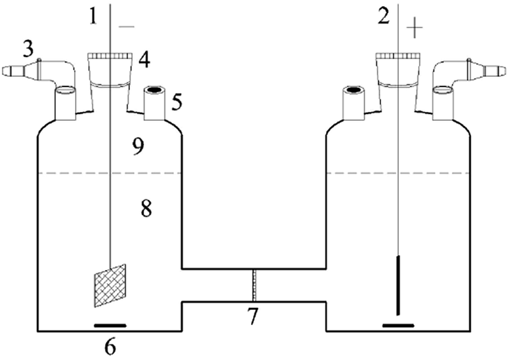 | ||
| Fig. 1 A schematic of the electrolytic cell for batch experiments, (1) Pd/CNTs–PPy/Ti cathode; (2) Pt anode; (3) expandable syringe; (4) gas-tight adapter; (5) sampling port; (6) stir bar; (7) cation-exchange membrane; (8) electrolyte (30 mL); (9) headspace of cell (10 mL). All adapters were fixed with tape and clamps. | ||
2.4 Analytical methods
The analytical equipments and methods for cyclic voltammetry (CV), transmission microscope (TEM), scanning electron microscope (SEM), X-ray diffractometer (XRD), inductively coupled plasma-atomic emission spectrometry (ICP-AES), and ion chromatography (IC) followed our previous relevant research.31,32 The level of CNTs surface charge was characterized by the zeta potential (Microtrac Zetatrac, USA), the concentration of CNTs dispersion was 0.5 mg mL−1, which pH value was adjusted by H2SO4 solution and NaOH solution. The concentrations of 2,3-DCP and intermediate products were detected by high performance liquid chromatography (HPLC, waters 1525 binary pump and waters 2489 UV/visible detector, USA, C18 column, Kromasil) at wavelength of 280 nm. The mobile phase was 30% water and 70% methanol with flow rate of 0.8 mL min−1.2.5 Calculation methods
The 2,3-DCP removal efficiency and the dechlorination efficiency were calculated following the methods reported in the literature.303. Results and discussion
3.1 Preparation parameters of CNTs pretreatment and electrophoretic deposition
To obtain a stable and high-efficient electrode, fabrication of homogeneous CNTs film on the PPy/Ti supporting electrode was an essential step, and it was achieved by electrophoretic deposition method. Several factors affect the electrophoretic deposition process, especially the zeta potential of CNTs suspension and the electrophoretic deposition time.33,34Fig. 2 shows the TEM images of CNTs under different ultrasonication time and reflux time. As shown in Fig. 2a, the raw CNTs had impurities and were poor dispersibility, which indicated the process of CNTs oxidation treatment was insufficient by ultrasonication for 1 h and reflux for 1 h (Fig. 2b). When extending ultrasonication time to 4 h, the treated CNTs behaved better dispersibility. Similar morphologies could be seen from Fig. 2c and d when the reflux time was further extended to 2 h. The oxidized CNTs appeared clean and ordered, and it indicated that the impurities were almost removed.
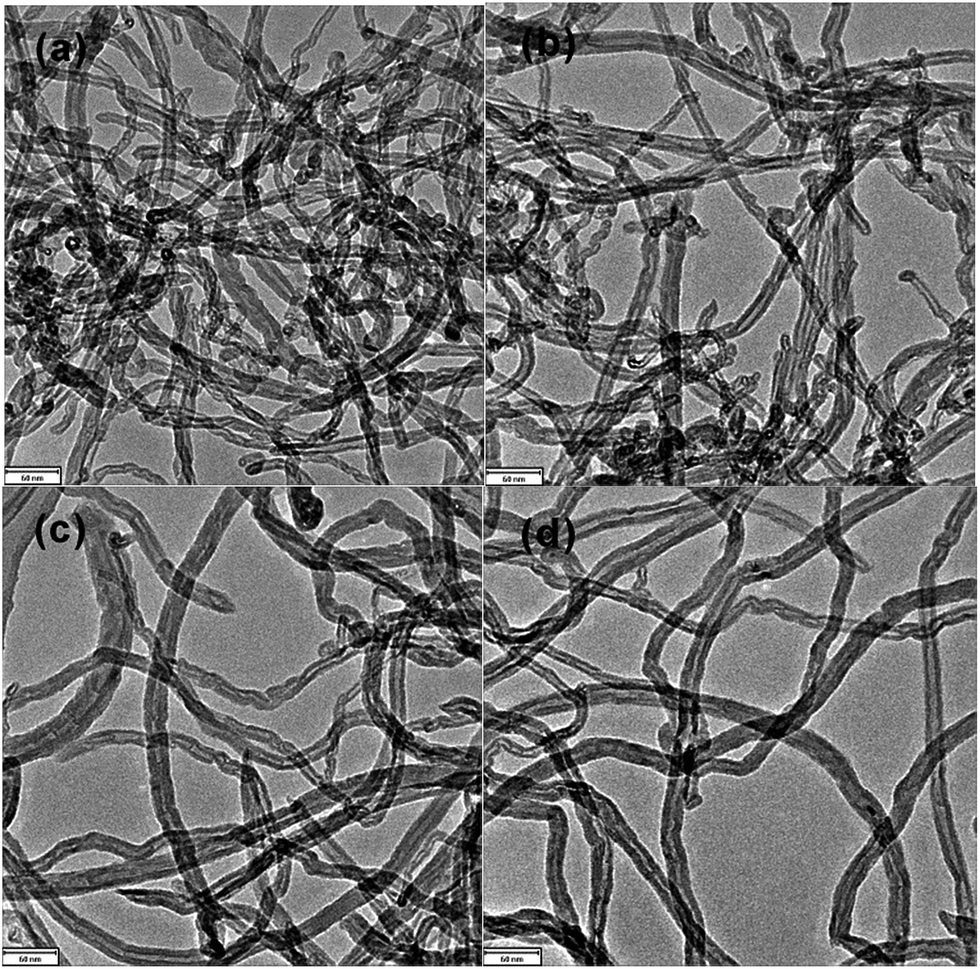 | ||
| Fig. 2 TEM images of CNTs with different chemical oxidation conditions. Raw CNTs (a), ultrasonication for 1 h and reflux for 1 h (b), ultrasonication for 4 h and reflux for 1 h (c), ultrasonication for 4 h and reflux for 2 h (d). | ||
A higher absolute value of the zeta potential indicates stability of CNTs' suspensions, which is favorable to CNTs deposition. If the absolute value of zeta potential is lower than 25 mV, the repulsive force between the particles is not strong enough to overcome the van der Waals force,34,39 resulting in agglomeration and sedimentation of the particles.
Fig. 3 shows the zeta potentials of CNTs' suspension with the different pH values, H2SO4 solution and NaOH solution were used to adjust the pH value of CNTs' suspension. The highest zeta potential absolute value, 53 mV, was achieved at pH value of 6 under condition of ultrasonication for 4 h and reflux for 2 h. The zeta potential absolute value became higher with the extension of reaction time, which indicated better stability of CNTs' suspension. This was because more active groups were introduced on the surface of CNTs with longer reaction time.
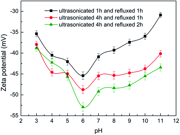 | ||
| Fig. 3 Zeta potentials of CNTs suspension as a function of pH and pretreatment condition. | ||
Therefore, ultrasonication for 4 h and reflux for 2 h at CNTs suspension pH value of 6 were selected as the appropriate CNTs pretreatment conditions.
 | ||
| Fig. 4 SEM images of CNTs films under different electrophoretic deposition time. 1 min (a), 3 min (b). | ||
3.2 Characterization of Pd/CNTs–PPy/Ti electrode
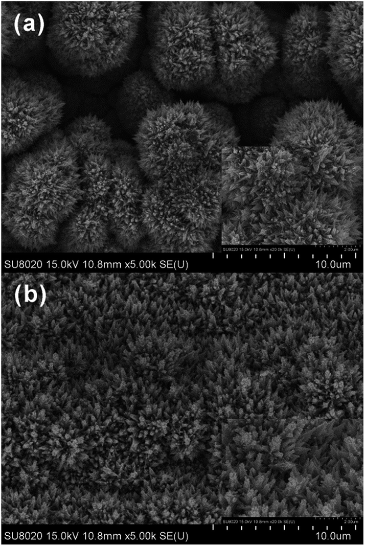 | ||
| Fig. 5 SEM images (5000×) of Pd/Ti electrode (a) and Pd/CNTs–PPy/Ti electrode (b). The insets are the SEM images (20000×). | ||
In previous studies,23 Pd particles deposited on the surface of Pd/PPy–SDBS/Ti electrode with conch-like shape, interestingly, the surface morphology of the Pd/CNTs–PPy/Ti electrode in this study appeared “pinpoint” shape, more compact and uniform, which could provide higher specific surface area and larger reaction contact sites for dechlorination process. This may be due to the effect of pulsed-current electrodeposition. As reported in the literature,40 dechlorination of CPs at Pd loaded electrode conformed to hydrogen spillover mechanism. H* generated firstly on a polarized Pd particle and then diffused to a less polarized nearby Pd article by spillover. It was proposed that the pinpoint like Pd on the Pd/CNTs–PPy/Ti could be polarized easily, which was conducive to H* generation and ECH of CPs.
 | ||
| Fig. 6 XRD patterns of Pd/CNTs–PPy/Ti electrode (a), Pd/Ti electrode (b) and Pd (JCPDS-ICDD, 87-0638). | ||
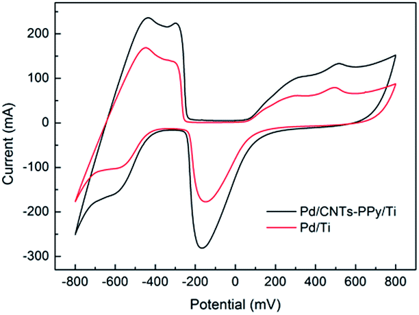 | ||
| Fig. 7 CV curves of prepared electrodes in 0.5 M H2SO4 solution. Scan rate: 50 mV s−1. | ||
As shown in Table 1, the hydrogen adsorption current value (at about −600 mV) of Pd/CNTs–PPy/Ti electrode was improved to −160 mA, which increased 55.3% compared with that of Pd/Ti electrode, −103 mA. According to the mechanism of ECH,43,44 the higher hydrogen adsorption current value in the voltammogram, the more hydrogen atoms were adsorbed on the electrode, which would contribute to a higher efficiency for electrochemical reductive dechlorination of CPs. Therefore, the electrocatalytic performance of electrodes was improved with the modification of CNTs–PPy interlayer. Pd/CNTs–PPy/Ti electrode had better potential for CPs dechlorination.
| Electrode | Hydrogen adsorption current (mA) | Pd (mg cm−2) | EASA (m2 g−1) |
|---|---|---|---|
| Pd/CNTs–PPy/Ti | 160 | 3.55 | 16.35 |
| Pd/Ti | 103 | 3.55 | 10.30 |
The loading levels of Pd particles on the prepared electrodes were investigated by ICP-AES. The Pd content on Pd/CNTs–PPy/Ti electrode and Pd/Ti electrode were both 3.55 mg cm−2.
The electrochemical active surface areas (EASA) of the prepared electrodes were calculated in light of the literatures.45–47 EASA ≈ Q/Km, where charge Q is based on the charge of hydrogen atoms adsorption/desorption in the CV test, m is the mass of Pd of the prepared electrodes and K is the Pd conversion factor which is 210 μC cm−2. The calculated EASA values were shown in Table 1, the EASA of Pd/CNTs–PPy/Ti electrode was improved to 16.35 m2 g−1, which increased 58.7% compared with that of the Pd/Ti electrode, 10.30 m2 g−1. Pd/CNTs–PPy/Ti electrode with lager EASA was more beneficial to the electrocatalytic reductive dechlorination of chlorophenols. The utilization efficiency of Pd was improved with the modification of CNTs–PPy interlayer.
3.3 Parameters of 2,3-DCP dechlorination
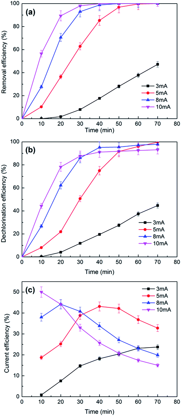 | ||
| Fig. 8 The effects of currents on the removal (a), dechlorination efficiency (b) and current efficiency (c) of 2,3-DCP dechlorination. Initial pH, 2.0. | ||
Fig. 8b plots the dechlorination efficiencies of 2,3-DCP varying with the applied current. During the first 30 min, higher dechlorination current led to higher dechlorination efficiency, which consisted with the removal tendency of 2,3-DCP. Dechlorination efficiency decreased when current increased after 30 min. 2,3-DCP dechlorination efficiencies at 70 min were 100%, 98% and 93% with the current of 5 mA, 8 mA and 10 mA, respectively. Dechlorination efficiency was lower than removal, possibly because the adsorption and dechlorination were carried out simultaneously, part of the adsorbed 2,3-DCP were not dechlorinated in time.
According to the previous studies,48,49 hydrogen evolution reaction (HER) occurred during the ECH process. The side reaction HER would be speeded up with the current increasing. In addition, when the concentration of 2,3-DCP decreased gradually, the HER process became more strong, which inhibited the ECH process. Fig. 8c shows the current efficiencies of 2,3-DCP dechlorination under different currents. When current of 10 mA was employed, the current efficiency decreased as time went on, indicated that HER influenced dechlorination process seriously at 10 mA. When current of 3 mA was used, the current efficiency increased over time. When currents of 5 mA and 8 mA were used, current efficiencies increased at the early stage and decreased latterly. The current efficiencies at 70 min under 8 mA and 10 mA were 19% and 15%, respectively, much lower than 32% achieved under 5 mA. Considering the reaction efficiency and the cost, 5 mA was selected as the appropriate dechlorination current. The lower energy consumption was part of cleaner production.
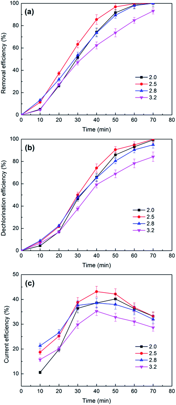 | ||
| Fig. 9 The effects of catholyte initial pH values on the removal (a) and dechlorination efficiency (b) and current efficiency (c) of 2,3-DCP dechlorination. Constant current, 5 mA. | ||
| pH value | ||||
|---|---|---|---|---|
| Initial | 2.00 | 2.50 | 2.80 | 3.20 |
| Terminal | 2.38 | 6.08 | 9.35 | 11.19 |
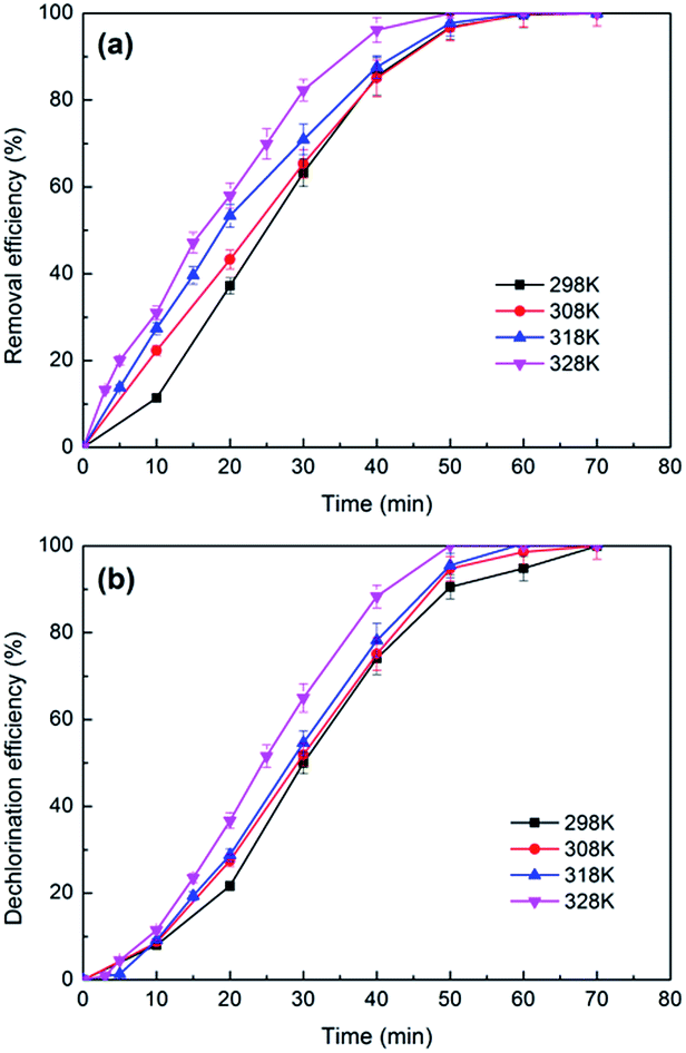 | ||
| Fig. 10 The effects of temperature on the removal (a) and dechlorination efficiency (b) of 2,3-DCP dechlorination. Constant current, 5 mA; initial pH, 2.5. | ||
The dechlorination experiments with addition of NO3−, CO32− and HCO3− were investigated under constant current of 5 mA and catholyte initial pH of 2.5. Results showed that the removal and dechlorination efficiency of 2,3-DCP could reach 100% within 70 min, almost similar to the control experiment, as shown in Fig. S2.† The addition of NO3−, CO32− and HCO3− had no obvious effect on the dechlorination.
Similarly, dechlorination experiments with addition of Mg2+, K+, Ca2+ were investigated under constant current of 5 mA and catholyte initial pH of 2.5. Both the removal and dechlorination efficiency of 2,3-DCP could reach 100%, as shown in Fig. S3.† No distinct change was observed in comparison to the control experiment, indicating that Mg2+, K+, Ca2+ had no obvious effect on the dechlorination.
3.4 Dechlorination pathways of 2,3-DCP
Fig. 11 plots the concentrations of 2,3-DCP and intermediates during the dechlorination. As the dechlorination of 2,3-DCP progressing, the concentration of phenol increased gradually. The concentration of 2-chlorophenol (2-CP) increased in the first 30 min and then decreased. No 3-chlorophenol (3-CP) was detected during the whole dechlorination process. Therefore, it was inferred that the pathways of 2,3-DCP dechlorination might follow two routes (Fig. 12): meta-Cl was dechlorinated firstly, generating 2-CP, which was dechlorinated further to phenol (route a); meta-Cl and ortho-Cl were dechlorinated simultaneously (route b). Phenol was the main dechlorination product of 2,3-DCP. The meta-Cl was substituted easier due to the steric hindrance effect.50,51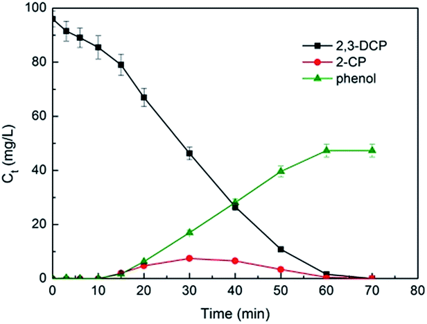 | ||
| Fig. 11 Variations of 2,3-DCP concentration and intermediate products concentration during the dechlorination. Constant current, 5 mA; initial pH, 2.5. | ||
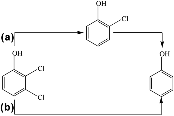 | ||
| Fig. 12 Proposed pathways of 2,3-DCP dechlorination. | ||
3.5 Long term performance of Pd/CNTs–PPy/Ti electrode
Under constant current of 5 mA and catholyte initial pH of 2.5, eight times consecutive reduction experiments with 2,3-DCP initial concentration of 100 mg L−1 were conducted. As shown in Fig. 13, complete removal and dechlorination could be achieved within 70 min in each experiment. This indicated that Pd/CNTs–PPy/Ti electrode had good stability.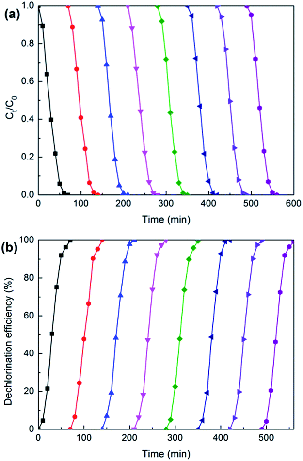 | ||
| Fig. 13 Variations of 2.3-DCP concentration (a) and dechlorination efficiency (b) during the repeated dechlorinations of 2,3-DCP on Pd/CNTs–PPy/Ti electrode. Constant current, 5 mA; initial pH, 2.5. | ||
3.6 The electrocatalytic comparison of Pd/CNTs–PPy/Ti electrode, Pd/PPy/Ti electrode, Pd/CNTs/Ti electrode and Pd/Ti electrode
The contrast experiments were used to further reveal the synergistic effect of Pd, CNTs, and polypyrrole for dechlorination of 2,3-dechlorophenol. In Fig. 14, it could be seen that the CV curve of Ti electrode nearly is a straight line, which meant the capacity of adsorbing hydrogen of Ti electrode could be negligible comparing with PPy/Ti electrode. Besides, compared with Ti electrode, it could be clearly seen that the increased hydrogen adsorption current of CNTs–PPy/Ti electrode (16.0 mA) was higher than the sum (6.1 mA) of PPy/Ti electrode and CNTs/Ti electrode. So the better electrocatalytic performance of CNTs–PPy/Ti electrode was likely to be the synergistic effect of Pd, CNTs, and polypyrrole.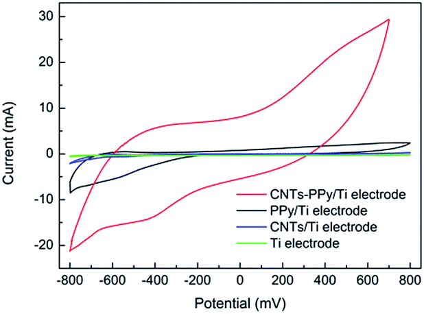 | ||
| Fig. 14 CV curves of CNTs–PPy/Ti electrode, PPy/Ti electrode, CNTs/Ti electrode and Ti electrode in 0.5 M H2SO4 solution. Scan rate: 50 mV s−1. | ||
In Fig. 15, it could be found that hydrogen adsorption current of CNTs–PPy/Ti electrode can be negligible comparing with Pd/CNTs–PPy/Ti electrode and Pd/Ti electrode. And hydrogen adsorption current of Pd/CNTs–PPy/Ti electrode was higher than the Pd/Ti electrode. It was likely to be the synergistic effect of Pd, CNTs, and polypyrrole to improve the electrocatalytic performance of the electrode. Besides, we further investigated the removal efficiency of Pd/CNTs–PPy/Ti electrode, Pd/PPy/Ti electrode, Pd/CNTs/Ti electrode and Pd/Ti electrode on 2,3-DCP dechlorination under the same conditions (constant current, 5 mA; initial pH, 2.5). Fig. 16 showed the removal efficiency of Pd/CNTs–PPy/Ti electrode was higher than the other three electrode, and the increased removal efficiency of the Pd/CNTs–PPy/Ti electrode (24.1%) was higher than the sum (13.0%) of Pd/PPy/Ti electrode and Pd/CNTs/Ti electrode compared with Pd/Ti electrode at 70 min, which meant the electrocatalytic performance of the electrode was promoted distinctively when the modified interlayer was CNTs–PPy. So the better electrocatalytic performance of Pd/CNTs–PPy/Ti electrode was likely to be the synergistic effect of Pd, CNTs, and polypyrrole.
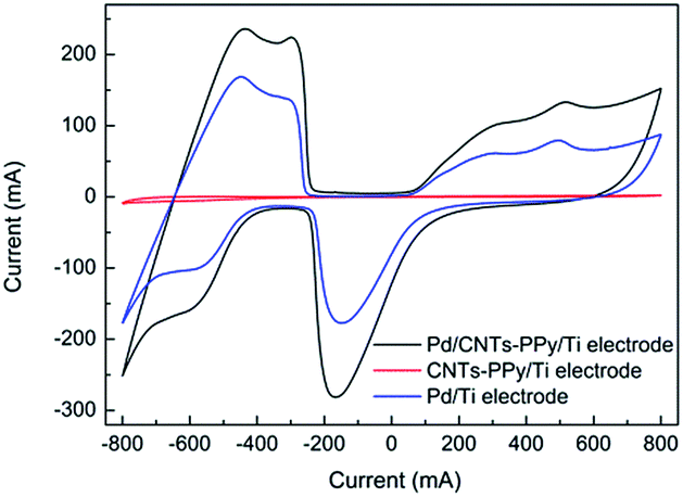 | ||
| Fig. 15 CV curves of Pd/CNTs–PPy/Ti electrode, CNTs–PPy/Ti electrode and Pd/Ti electrode in 0.5 M H2SO4 solution. Scan rate: 50 mV s−1. | ||
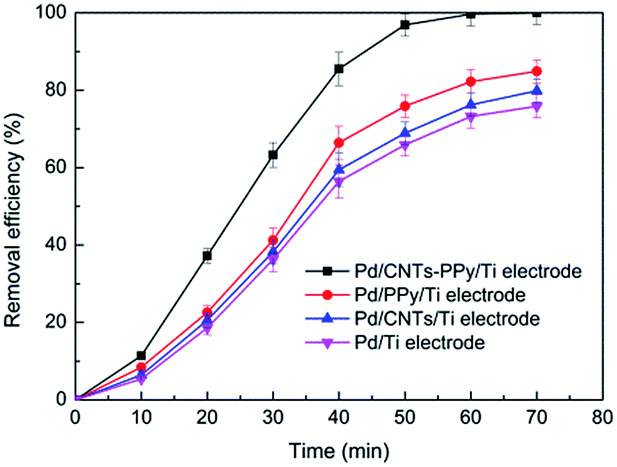 | ||
| Fig. 16 The removal efficiency of Pd/CNTs–PPy/Ti electrode, Pd/PPy/Ti electrode, Pd/CNTs/Ti electrode and Pd/Ti electrode on 2,3-DCP dechlorination. Constant current, 5 mA; initial pH, 2.5. | ||
4. Conclusions
Pd loaded electrode with the modification of CNTs–PPy interlayer showed higher electrocatalytic activity. CNTs–PPy interlayer made Pd particles uniformly deposit on the electrode surface. Pulsed-current electrodeposition technique made the electrode surface get a finer grain structure, and Pd particles were more compact and smaller. Pd/CNTs–PPy/Ti electrode had higher hydrogen adsorption current value of −160 mA and larger EASA of 16.35 m2 g−1. 2,3-DCP could be completely removed and 100% dechlorinated under constant current of 5 mA and catholyte initial pH of 2.5 within 70 min on Pd/CNTs–PPy/Ti electrode. The common ions in aqueous solution including NO3−, CO32−, HCO3−, Mg2+, K+ and Ca2+, had no obvious effect on the dechlorination within the scope of investigation. The intermediates of 2,3-DCP dechlorination were 2-CP and phenol. Pd/CNTs–PPy/Ti electrode presents the application potential due to its good stability and high electrocatalytic activity.Acknowledgements
This work was supported by National Natural Science Foundation of China (51478014 and 51278006), Cultivation Fund for Beijing New Century Hundred, Thousand and Ten Thousand Talents Project.Notes and references
- D. M. Zhao, Y. Y. Zheng, M. Li, S. A. Baig, D. L. Wu and X. H. Xu, Ultrason. Sonochem., 2014, 21, 1714–1721 CrossRef CAS PubMed.
- F. Y. Kong, A. J. Wang and H. Y. Ren, Bioresour. Technol., 2014, 166, 252–258 CrossRef CAS PubMed.
- X. Y. Wang, M. P. Zhu, H. L. Liu, J. Ma and F. Li, Sci. Total Environ., 2013, 449, 157–167 CrossRef CAS PubMed.
- X. Fan, K. Lai, L. Wang, H. Qiu, J. Yin, P. Zhao, S. Pan, J. Xu and C. Wang, J. Mater. Chem. A, 2015, 3, 12179–12187 CAS.
- K. Wang, P. Chen and S. Huang, Anal. Bioanal. Chem., 2014, 406, 2123–2131 CrossRef CAS PubMed.
- B. P. Patel and A. Kumar, Desalin. Water Treat., 2016, 57, 15932–15940 CrossRef CAS.
- R. Cheng, W. Zhou, J. L. Wang, D. D. Qi, L. Guo, W. X. Zhang and Y. Qian, J. Hazard. Mater., 2010, 180, 79–85 CrossRef CAS PubMed.
- J. N. Solanki and Z. Murthy, Ind. Eng. Chem. Res., 2011, 50, 14211–14216 CrossRef CAS.
- C. Sun, S. A. Baig, Z. Lou, J. Zhu, Z. Wang, X. Li, J. Wu, Y. Zhang and X. Xu, Appl. Catal., B, 2014, 158, 38–47 CrossRef.
- A. A. Isse, B. Huang, C. Durante and A. Gennaro, Appl. Catal., B, 2012, 126, 347–354 CrossRef CAS.
- Y. H. Xu, Q. Q. Cai, H. X. Ma, Y. He, H. Zhang and C. A. Ma, Electrochim. Acta, 2013, 96, 90–96 CrossRef CAS.
- Z. Q. He, J. J. Sun, J. Wei, Q. Wang, C. X. Huang, J. M. Chen and S. Song, J. Hazard. Mater., 2013, 250, 181–189 CrossRef PubMed.
- J. J. Li, H. L. Liu, X. W. Cheng, Q. H. Chen, Y. J. Xin, Z. P. Ma, W. X. Xu, J. Ma and N. Q. Ren, Chem. Eng. J., 2013, 225, 489–498 CrossRef CAS.
- W. Y. Yu, G. M. Mullen and C. B. Mullins, J. Phys. Chem. C, 2013, 117, 19535–19543 CAS.
- M. de Oca, H. Kurnarakuru, D. Cherns and D. J. Fermin, J. Phys. Chem. C, 2011, 115, 10489–10496 Search PubMed.
- S. R. de Debiaggi, E. A. Crespo, F. U. Braschi, E. M. Bringa, M. L. Ali and M. Ruda, Int. J. Hydrogen Energy, 2014, 39, 8590–8595 CrossRef.
- R. El Far, D. E. Diaz-Droguett, S. Rojas, J. I. Avila, C. P. Romero, P. Lievens and A. L. Cabrera, Thin Solid Films, 2012, 522, 199–203 CrossRef CAS.
- H. Ahmad, M. M. Rahman, M. A. Ali, H. Minami, K. Tauer, M. A. Gafur and M. M. Rahman, J. Magn. Magn. Mater., 2016, 412, 15–22 CrossRef CAS.
- Y. S. Ko and J. Yim, Polymer, 2016, 93, 167–173 CrossRef CAS.
- Z. R. Sun, X. F. Wei, Y. B. Han, S. Tong and X. Hu, J. Hazard. Mater., 2013, 244, 287–294 CrossRef PubMed.
- Z. R. Sun, X. F. Wei, H. T. Shen and X. Hu, Electrochim. Acta, 2014, 129, 433–440 CrossRef CAS.
- Z. R. Sun, X. F. Wei, X. Hu, K. Wang and H. T. Shen, Colloids Surf., A, 2012, 414, 314–319 CrossRef CAS.
- Z. R. Sun, X. F. Wei, H. Zhang and X. Hu, Environ. Sci. Pollut. Res., 2015, 22, 3828–3837 CrossRef CAS PubMed.
- K. Yang and B. S. Xing, Chem. Rev., 2010, 110, 5989–6008 CrossRef CAS PubMed.
- M. Badard, A. Combessis, A. Allais and L. Flandin, Polymer, 2016, 82, 198–205 CrossRef CAS.
- K. Chu and S. Park, J. Ind. Eng. Chem., 2016, 35, 195–198 CrossRef CAS.
- J. Xu, X. S. Lv, J. D. Li, Y. Y. Li, L. Shen, H. Y. Zhou and X. H. Xu, J. Hazard. Mater., 2012, 225, 36–45 CrossRef PubMed.
- Z. Sun, H. Zhang, X. Wei, R. Du and X. Hu, J. Electrochem. Soc., 2015, 162, H590–H596 CrossRef CAS.
- Z. Sun, H. Zhang, X. Wei, X. Ma and X. Hu, J. Solid State Electrochem., 2015, 19, 2445–2456 CrossRef CAS.
- Z. Sun, X. Wei, H. Shen and X. Hu, Electrochim. Acta, 2014, 129, 433–440 CrossRef CAS.
- Z. Sun, X. Wei, H. Zhang and X. Hu, Environ. Sci. Pollut. Res., 2015, 22, 3828–3837 CrossRef CAS PubMed.
- Z. Sun, X. Wei, H. Shen and X. Hu, Electrochim. Acta, 2014, 129, 433–440 CrossRef CAS.
- A. Fraczek-Szczypta, E. Dlugon, A. Weselucha-Birczynska, M. Nocun and M. Blazewicz, J. Mol. Struct., 2013, 1040, 238–245 CrossRef CAS.
- W. Qian, M. Cao, F. Xie and C. Dong, Nano-Micro Lett., 2016, 8, 240–246 CrossRef.
- A. Benko, A. Przekora, A. Weselucha-Birczynska, M. Nocun, G. Ginalska and M. Blazewicz, Appl. Phys. A: Mater. Sci. Process., 2016, 122, 447 CrossRef.
- K. A. Wepasnick, B. A. Smith, K. E. Schrote, H. K. Wilson, S. R. Diegelmann and D. H. Fairbrother, Carbon, 2011, 49, 24–36 CrossRef CAS.
- M. Hakamada, A. Moriguchi, S. Matsumura and M. Mabuchi, Thin Solid Films, 2013, 531, 99–102 CrossRef CAS.
- B. Thomas, A. R. Boccaccini and M. Shaffer, J. Am. Ceram. Soc., 2005, 88, 980–982 CrossRef CAS.
- A. Sarkar and D. Hah, J. Electron. Mater., 2012, 41, 3130–3138 CrossRef.
- B. Yang, G. Yu and J. Huang, Environ. Sci. Technol., 2007, 41, 7503–7508 CrossRef CAS PubMed.
- Z. Sun, H. Shen, X. Wei and X. Hu, Chem. Eng. J., 2014, 241, 433–442 CrossRef CAS.
- G. Zhu, L. K. Pan, T. Lu, X. J. Liu, T. Lv, T. Xu and Z. Sun, Electrochim. Acta, 2011, 56, 10288–10291 CrossRef CAS.
- H. Cheng, K. Scott and P. A. Christensen, Electrochim. Acta, 2004, 49, 729–735 CrossRef CAS.
- J. T. Zhang, M. H. Huang, H. Y. Ma, F. Tian, W. Pan and S. H. Chen, Electrochem. Commun., 2007, 9, 1298–1304 CrossRef CAS.
- A. N. Correia, L. H. Mascaro, S. Machado and L. A. Avaca, Electrochim. Acta, 1997, 42, 493–495 CrossRef CAS.
- A. Pozio, M. De Francesco, A. Cemmi, F. Cardellini and L. Giorgi, J. Power Sources, 2002, 105, 13–19 CrossRef CAS.
- S. W. Li, Z. P. Dong, H. L. Yang, S. J. Guo, G. L. Gou, R. Ren, Z. J. Zhu, J. Jin and J. T. Ma, Chem.–Eur. J., 2013, 19, 2384–2391 CrossRef CAS PubMed.
- Z. R. Sun, K. Wang, X. F. Wei, S. Tong and X. Hu, Int. J. Hydrogen Energy, 2012, 37, 17862–17869 CrossRef CAS.
- Z. R. Sun, X. F. Wei, H. T. Shen and X. Hu, Electrochim. Acta, 2014, 129, 433–440 CrossRef CAS.
- A. I. Tsyganok, I. Yamanaka and K. Otsuka, Chemosphere, 1999, 39, 1819–1831 CrossRef CAS.
- J. Han, R. L. Deming and F. M. Tao, J. Phys. Chem. A, 2004, 108, 7736–7743 CrossRef CAS.
Footnote |
| † Electronic supplementary information (ESI) available. See DOI: 10.1039/c7ra02515g |
| This journal is © The Royal Society of Chemistry 2017 |