
 Open Access Article
 This Open Access Article is licensed under a
 Creative Commons Attribution 3.0 Unported Licence
Inhibited/enhanced fluorescence of embedded fluorescent defects by manipulation of spontaneous emission based on photonic stopband†
Feng Jin‡
a,
Liang Xu‡b,
Mei-Ling Zheng a,
Jing-Xia Wanga,
Xian-Zi Donga,
Zhen-Sheng Zhaoa,
Yan-Lin Song*b and
Xuan-Ming Duan*ac
a,
Jing-Xia Wanga,
Xian-Zi Donga,
Zhen-Sheng Zhaoa,
Yan-Lin Song*b and
Xuan-Ming Duan*ac
aLaboratory of Organic NanoPhotonics, CAS Key Laboratory of Bio-inspired Materials and Interfacial Science, Technical Institute of Physics and Chemistry, Chinese Academy of Sciences, Beijing, 100190, P. R. China. E-mail: xmduan@mail.ipc.ac.cn; Fax: +86-10-82543596; Tel: +86-10-82543596
bBeijing National Laboratory for Molecular Sciences (BNLMS), Key Laboratory of Green Printing, Key Laboratory of Organic Solids, Institute of Chemistry, Chinese Academy of Sciences, Beijing, 100190, P. R. China. E-mail: ylsong@iccas.ac.cn
cChongqing Institute of Green and Intelligent Technology, Chinese Academy of Sciences, Chongqing, 400714, P. R. China
First published on 3rd April 2017
Abstract
Inhibition and enhancement of the fluorescence from embedded fluorescent defects in colloidal crystals (CCs) is demonstrated. The embedded defects, which are verified by the passbands and scanning electron microscope images, are fabricated inside the CCs by employing two-photon polymerization of allyl-fluorescein (allyl-FL) doped photoresist. The fluorescence image is indistinct when the photoluminescence band of allyl-FL locates at the photonic stopband. However, a bright fluorescence image is observed when the photoluminescence band is located at the photonic stopband edge. The inhibition and enhancement in fluorescence is ascribed to the manipulation of the spontaneous emission of the allyl-FL by the photonic stopband, which is verified by the fluorescence spectra of the allyl-FL infiltrated in the CCs with different photonic stopbands. This study will be prospective in bio-imaging and miniature lasers.
Introduction
Colloidal crystals (CCs) are three dimensional photonic crystals, in which the propagation of photons within a certain frequency band is forbidden due to Bragg diffraction, resulting in the formation of a photonic stopband.1,2 Numerous potential applications have been explored by utilizing photonic stopbands of the CCs, including low-threshold lasers,3–5 sensors,6,7 batteries,8 solar cells,9 ultrasensitive detection,10 anti-counterfeiting,11 and displays.12 Well-designed and controllably positioned defects in CCs are often required to achieve these purposes. The introduction of artificial defects in the CCs could tailor the optical properties by creating optical states in the photonic stopbands, which is analogous to the function that semiconductors do with electrons. Great efforts have been made in the controlled incorporation of artificial defects inside the CCs.13–19 Two-photon polymerization (TPP) is a versatile top-down method for the controlled insertion of designed defects into a CC with high resolution and precise position, in which the photochemical process is confined to a focal volume of the order of the cube of the excitation wavelength.20 Rinne et al. have created designed defects in an opal CC via TPP, and demonstrated the waveguiding properties after silicon replication.21 Nelson et al. have fabricated embedded defects with excellent lattice registration and precise placement in the CC, and found the dependence of optical properties on the placement of the defects in the CCs.22 Lange et al. have created three-dimensional fluorescent defects inside inverse opal CC, and demonstrated the confinement of the fluorescence emission by the photonic stopband.23 Although inhibition of spontaneous emission has been observed in the localized defects in colloidal crystals, fluorescence enhancement of the embedded fluorescent defects still remains a big challenge. The absence of fluorescence enhancement will not only limit the comprehensive understanding of light–matter interaction in CCs, but also hinder the application of CCs in novel optical devices, for example miniature laser.In this paper, we have demonstrated inhibited and enhanced fluorescence of the embedded defects by the incorporation of designed fluorescent defects in CCs with different photonic stopband. Embedded fluorescent microstructures were fabricated inside poly(St-MMA-AA) CCs with different photonic stopband via TPP using allyl-fluorescein (allyl-FL) doped photoresist.24 Manipulation of the fluorescent images were obtained by modification of the emission characteristics of the dye in the embedded features based on the different overlapping of the fluorescence and the photonic stopband. The fluorescent image manipulation was attributed to the fluorescence engineering of the dye molecules by the photonic stopband of the CCs. This study not only helps the understanding of the light–matter interaction in CCs, but also provides the prospective in achieving novel optical applications, such as cell imaging, and miniature lasers.
Results and discussion
Embedded fluorescent features were fabricated in the CCs via TPP of allyl-FL doped liquid photoresist. First, poly(St-MMA-AA) CCs were self-assembled from monodisperse microspheres on glass substrates via vertical deposition method according to previous procedure.25 Second, CCs were infiltrated with allyl-FL doped photoresist by dropping 0.1 mL of SCR500 doped with allyl-FL on a sandwiched structure, which was constructed by covering a piece of glass slide assembled with CC on another piece of glass slide that fixed on a piezostage (Scheme 1(a)-1). Wherein, capillary force drew the photoresist into the void space. Allyl-FL doped photoresist was prepared by mixing allyl-FL and commercial photoresist SCR500, which was selected considering the good chemical stability of poly(St-MMA-AA) CCs in it. Third, TPP was performed by using a femtosecond laser beam (center wavelength of 780 nm, pulse width of 80 fs, and repetition rate of 82 MHz), which was focused into the infiltrated photoresist to make 3D scans according to programmable designs, resulting in polymerization of 3D microstructures with dye simultaneously doped inside the polymer (Scheme 1(a)-2 and (b)).26 The laser power was fixed at 20 mW, and the scanning speed was 22 μm s−1. Finally, the polymerized features were left in the CCs as embedded fluorescent defects, while the unpolymerized photoresist was washed out with ethanol (Scheme 1(a)-3).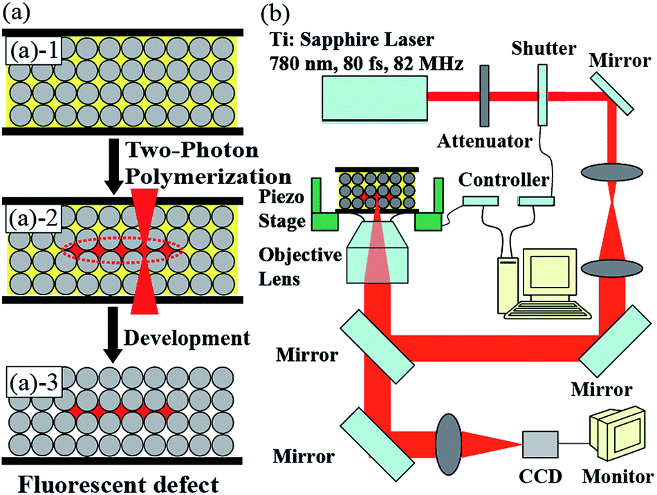 | ||
| Scheme 1 (a) Schematic illustration of the embedded fluorescent defects fabricated in CC via two-photon polymerization (TPP). (b) Experimental setup of the TPP. | ||
Optical properties of allyl-FL doped polymer film were evaluated by measuring the absorption and fluorescence spectra, as shown in Fig. 1(a). The allyl-FL doped polymer film showed maximum absorbance at the wavelength of 462 nm, and exhibited fluorescence peak at the wavelength of 533 nm with a shoulder peak at 552 nm. Compared with the chloroform solution of allyl-FL (Fig. S1, ESI†), there is a red-shift of 8 nm for the fluorescence spectrum, but the absorption spectrum of the allyl-FL doped polymer remains the same. The inset of Fig. 1(a) exhibited the molecular structure of allyl-FL, in which the fluorescein was modified by introducing a bulky allyl group into the molecular structure. This design would result in the improved solubility of the dye in photoresist, and suppression of the aggregation of the dye molecules after doping in polymer.3,27,28
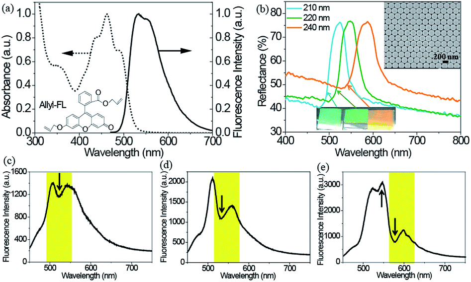 | ||
| Fig. 1 (a) Absorption (dot line) and fluorescence (solid line) spectra of 1 wt% allyl-FL doped polymer film. The inset is the molecular structure of allyl-FL. (b) Reflectance spectra of the CCs assembled with 210, 220, and 240 nm poly(St-MMA-AA) microspheres, respectively. The inset is top-view scanning electron microscope image of the CC with 210 nm poly(St-MMA-AA) microsphere. (c) Fluorescence spectra of allyl-FL infiltrated CCs with (c) 210, (d) 220, and (e) 240 nm poly(St-MMA-AA) microspheres, respectively. The yellow regions show the photonic stopband of the CCs. | ||
Reflectance spectra of the CCs were derived in normal incidence to the substrate to evaluate the photonic stopband. As shown in Fig. 1(b), reflected bands were located at the wavelength of 525, 542, and 590 nm, indicating the (111) planes photonic stopband of the CCs with diameters of 210, 220, and 240 nm (donated as CC525nm, CC542nm, and CC590nm). The maximum reflectivity of the CCs was determined to be 76%, 77%, and 76%, respectively, on a UV-Vis-NIR Spectrophotometer (Carry 5000, Varian) by using commercial polytetrafluoroethylene plate as the reference. Due to Bragg diffraction, the CCs displayed bright iridescent colours from cyan to orange, indicating the long-range ordered stack of the CCs, which was further verified by the scanning electron microscope (SEM) image of the CC525nm, as shown in the inset of Fig. 1(b). Consequently, the high-quality of the CCs was confirmed by the well-ordered hexagonal structure, high reflectivity and bright iridescence. By varying the size of poly(St-MMA-AA) microspheres, the relationship of the photonic stopband of the CCs and the fluorescence band of the allyl-FL doped polymer is overlapping or partial overlapping. The overlapping of the photonic stopband and the fluorescence band is of great importance to manipulate spontaneous emission of dye molecules. Therefore, the fluorescence of the allyl-FL is expected to be considerably modified by the CCs.29
Fluorescence engineering of allyl-FL by the CCs was demonstrated by tailoring the overlapping of the photonic stopband and the fluorescence band for allyl-FL infiltrated CCs. The infiltration was achieved by soaking the CCs in ethanol solution of allyl-FL, and dried in air. Fig. 1(c)–(e) show the fluorescence spectra of the allyl-FL incorporated in the CCs. As plotted in Fig. 1(c), a trough at 525 nm occurs on the fluorescence spectrum for the CC525nm, which is located at the photonic stopband of the CC525nm, indicating the inhibition of the spontaneous emission by the photonic stopband due to the good overlapping of the fluorescence band and photonic stopband. Meanwhile, the overall fluorescence intensity of the allyl-FL molecule was reduced in the CC. Similarly, for the CC542nm shown in Fig. 1(d), the fluorescence spectrum also reveals the suppression of the spontaneous emission by the CC. Although there is also a drop on the fluorescence spectrum, the wavelength of the dip is red-shifted, which is attributed to the red-shift of the photonic stopband. Besides, the fluorescence intensity in CC542nm is about 1.5 times larger than that of CC525nm. However, for the CC590nm in Fig. 1(e), both attenuation and enhancement of the spontaneous emission are simultaneously observed on the fluorescence spectrum. The attenuation of the spontaneous emission is verified by the evident drop of the fluorescence intensity at 580 nm. Whereas, the enhancement of the fluorescence emission is confirmed by the fact that the emission intensity at 550 nm is higher than that at 525 nm, since the former is lower than the latter for allyl-FL, as shown in Fig. 1(a) and S1.† The emission enhancement occurs on the blue side of the photonic stopband, which could be attributed to the band edge effect of the CCs.3,30–35 The modification of the CCs on the spontaneous emission of the allyl-FL infiltrated in the CCs suggests that fluorescent intensity of the embedded fluorescent defects would be affected by the CCs.
Artificial localized defects without allyl-FL were incorporated in the CCs via TPP of SCR500. Fig. 2(a) illustrated the introduction of planar defects in the CCs at different positions. To demonstrate the ability to create embedded defects inside the CCs, rectangular microstructures with the same position of the planar defects (50 μm × 50 μm × 1 μm) were fabricated with 3/4 inside the CC, while the other 1/4 suspended on the edge of the CC. To do this, the laser focus was controlled to move from inside of the CC to the space outside of the CC. Consequently, the embedded feature was produced inside the CC, while the other part on the edge of the CC. SEM images showed that rectangular features were successfully incorporated into the CCs with different positions (Fig. 2(b)–(d)). It's clear that the CCs almost retained the ordered structure after experiencing the photoresist infiltration, TPP fabrication of embedded defect, and subsequent development in ethanol, indicating the stability of the colloidal crystals during the incorporation of embedded defects. For the upper, middle and bottom defects, the rectangular features are precisely located at the positions of upper surface, center and bottom of the CCs, respectively. The optical properties of the CCs with and without embedded defects were investigated by measuring the reflection and transmittance spectra. Compared to the bare colloidal crystals, the embedded defects effectively broke the translational symmetry of the colloidal crystals, and resulted in a pronounced dip in the reflectance spectra (black arrow) or obvious peak in the transmittance spectra as shown in Fig. 2(e), indicating the introduction of a propagation state in the photonic stopband. The emergence of the propagation state suggests the appearance of defect mode in the CCs. It's worth noting that the defect mode is significantly influenced by the position of the embedded defects. The values of Rdip/Rpeak (the ratio of reflectance of the dip and peak value) for upper, center and bottom defects are 0.84, 0.49 and 0.74, respectively. Obviously, the defect mode is much more pronounced for embedded defect located at the center position of the CC than that located at the upper and bottom positions of the CCs. The position dependence of the defect mode is similar to the previous report.22 In the following part, embedded fluorescent defects were incorporated into the center location of the CCs to further investigate their fluorescent characteristics.
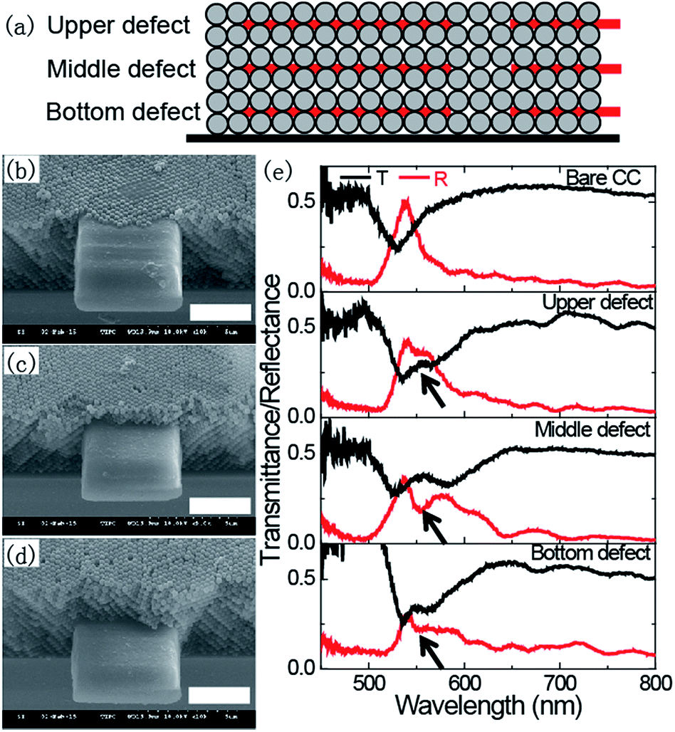 | ||
| Fig. 2 (a) Illustration of the embedded defects fabricated in CCs via TPP at different positions. SEM images of embedded defects extended outside the CCs for (b) upper, (c) middle, and (d) bottom defects. The scale bar is 3 μm. (e) Transmittance (black) and reflectance (red) spectra of bare CC and CCs with embedded defects at upper, middle, and bottom positions. The black arrow indicates the defect mode. | ||
Embedded fluorescent defects were incorporated in the CCs via TPP of allyl-FL doped SCR500. Fig. 3(a) shows SEM image of the microstructure fabricated in the CC. The rectangle structure was expanded and suspended from the edge of the CC, at the center of the CC. Furthermore, the embedded fluorescent defect was also confirmed by the optical microscope and confocal fluorescence microscope images. In optical microscope image, not only suspended feature, but also embedded defect can be recognized in Fig. 3(b). The embedded defect can be further verified by a confocal fluorescence microscope image, as presented in Fig. 3(c). The fluorescent image reveals a recognized fluorescent rectangle microstructure by comparing to the background with negligible fluorescence. The fluorescence brightness of the embedded feature is much weaker than that of the suspended defect, because only void space, i.e. 24% of the CC, is occupied by the polymerized fluorescent photoresist for the embedded defect. Moreover, the embedded defect is confirmed by the fluorescence intensity profile of the fluorescent feature, as shown in Fig. 3(d). Fluorescence intensity of region 2 is only one-third of that for region 3, while it is 4 times of that for region 1 and 4. The fluctuation of fluorescence intensity in region 2 is observed and attributed to the different fluorescent property of the microsphere and the dye-doped polymerized feature. Consequently, embedded fluorescent defects can be successfully constructed inside the CC via TPP of allyl-FL doped photoresist, which is verified by SEM, optical microscope and confocal fluorescence microscope images.
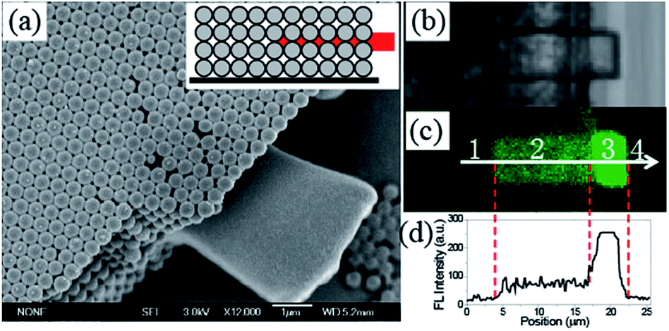 | ||
| Fig. 3 (a) SEM image of fluorescent feature fabricated in the CC via TPP. Inset is the illustration of the fluorescent feature in the CC. (b) Optical microscope image and (c) confocal fluorescence microscope image of the fluorescent feature in the CC. (d) Fluorescent intensity profile of the arrow shown in (c). | ||
Inhibition and enhancement of fluorescence for the embedded fluorescent defects was further demonstrated by investigating the fluorescent imaging characteristics of the embedded fluorescent defects in the CCs. Although the inhibition of the fluorescent image of embedded defects in CCs has been observed elsewhere,23 the fluorescence enhancement of the fluorescent image has not been reported yet, which will facilitate the investigation of bioimaging and miniature lasers. In our experiment, embedded character “A” was fabricated inside the CCs with different photonic stopband via TPP, and optical and fluorescent images of the embedded defects were explored. Fig. 4 shows the optical microscope and confocal microscope images of the embedded character “A”. In transmittance mode, similar images of the character “A” were observed in the CCs. The feature in CC590nm is much distinct than that in CC525nm and CC542nm, due to the larger void in the CC590nm. However, the fluorescent images of the embedded characters are quite different for the CCs with varied photonic stopband. Only indistinct fluorescent image is recognized for the embedded feature in the CC525nm, while bright fluorescent images can be observed for the features embedded in the CC542nm, and CC590nm, respectively. The difference in confocal microscope images is mainly attributed to modified spontaneous emission by the photonic stopband.36–38 As shown in Fig. 1(c) and (e), the fluorescence of allyl-FL is inhibited and enhanced in the CC525nm and CC590nm. As a result, the fluorescent image of the embedded character is faint in the CC525nm due to the inhibition of the fluorescence by the photonic stopband. Nevertheless, the fluorescent image of the embedded character is bright in the CC590nm, which is attributed to the enhancement of the fluorescence by the photonic stopband edge effect. Consequently, embedded fluorescent defects in CCs are capable of trapping light, and hold great prospect for optical applications.
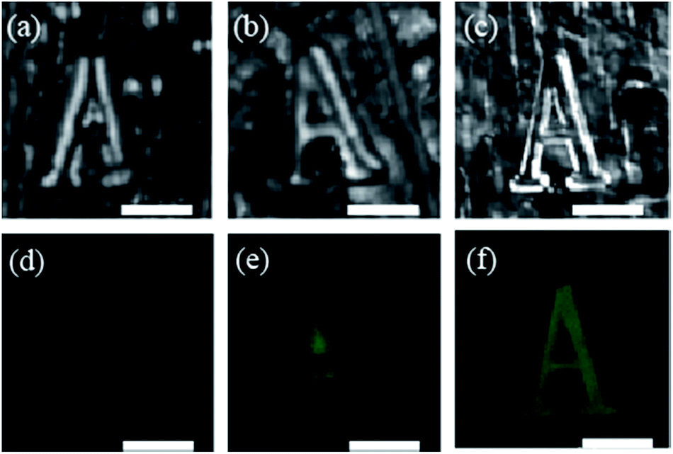 | ||
| Fig. 4 Optical microscope images of embedded character in CCs with photonic stopbands of (a) 525 nm, (b) 542 nm, and (c) 590 nm, respectively. Confocal fluorescence microscope images of embedded character in CCs with photonic stopband of (d) 525 nm, (e) 542 nm, and (f) 590 nm, respectively. The scale bar is 10 μm. | ||
Experimental
Embedded defects were fabricated via TPP by employing a mode-locked Ti:Sapphire laser (Tsunami, Spectra-Physics), which was tightly focused by an oil-immersion objective lens (N.A. = 1.45, 100×, Olympus). To demonstrate the ability to precisely incorporate defects inside CCs with different thickness, rectangular microstructures were fabricated with 3/4 inside the CC, while the other 1/4 suspended on the edge of the CC. Planar defects (50 μm × 50 μm × 1 μm) were constructed inside CCs with the same position of the rectangular microstructures to characterize the defect mode. Embedded fluorescent rectangle and character “A” was fabricated inside the CCs with different photonic stopbands to explore the fluorescent images.Absorption and fluorescence (FL) spectra were collected using a Shimadzu UV-2550 spectrometer and Hitachi F-4500 fluorescence spectrometer, respectively. SEM images were obtained with a field emission SEM (JEOL 6700F, Japan). The reflectance spectra of the CCs were measured employing a UV-Vis-NIR Spectrophotometer (Carry 5000, Varian). In order to explore the photonic stopband effect of the CCs on the FL spectra, FL spectra of allyl-FL doped CCs were measured by infiltrating allyl-FL in the CCs with different photonic stopbands. Optical transmission and reflection spectra of the embedded defects were evaluated by using Fourier transform infrared spectroscopy (FTIR, Bruker). A confocal laser scanning microscope (FV1000-IX 81, Olympus) was used to investigate the fluorescent images of the embedded features.
Conclusions
In conclusion, we have investigated the optical properties of the embedded fluorescent defects in poly(St-MMA-AA) CCs with different photonic stopbands. The embedded defects were incorporated inside the CCs via TPP of allyl-FL doped photoresist. By tuning the overlapping of fluorescence of the dye and photonic stopbands of the CCs, inhibition and enhancement of the fluorescence was observed for the embedded defects. The difference of the fluorescent images was attributed to modification of the spontaneous emission of the dye molecules by employing the photonic stopband effect of the CC. The embedded defect is a promising platform for studying light–matter interaction in the CCs, and has potential applications in bio-imaging and miniature lasers.Acknowledgements
The authors are grateful to the National Natural Science Foundation of China (Grant No. 51473176, 91323301, 51673208, 61475164, 51673207, 21421061, 51373183, 61275048 and 51003113), and the National Key Research and Development Program of China (2016YFA0200500 and 2016YFC1100500).Notes and references
- E. Yablonovitch, Phys. Rev. Lett., 1987, 58, 2059–2062 CrossRef CAS PubMed.
- S. John, Phys. Rev. Lett., 1987, 58, 2486–2489 CrossRef CAS PubMed.
- L. T. Shi, F. Jin, M. L. Zheng, X. Z. Dong, W. Q. Chen, Z. S. Zhao and X. M. Duan, Phys. Chem. Chem. Phys., 2016, 18, 5306–5318 RSC.
- F. D. Stasio, L. Berti, M. Burger, F. Marabelli, S. Gardin, T. Dainese, R. Signorini, R. Bozio and D. Comoretto, Phys. Chem. Chem. Phys., 2009, 11, 11515–11519 RSC.
- K. Zhong, L. W. Liu, X. D. Xu, M. Hillen, A. Yamada, X. P. Zhou, N. Verellen, K. Song, S. V. Cleuvenbergen, R. Vallee and K. Clay, ACS Photonics, 2016, 3, 2330–2337 CrossRef CAS.
- S. Lee, Y.-L. Lee, B. Kim, K. Kwon, J. Park, K. Han, H. Lee and W. Lee, Sens. Actuators, B, 2016, 231, 256–264 CrossRef CAS.
- Y. Q. Zhang, Q. Q. Fu and J. P. Ge, Nat. Commun., 2015, 6, 7510 CrossRef CAS PubMed.
- H. G. Zhang, T. Shi, D. J. Wetzel, R. G. Nuzzo and P. V. Braun, Adv. Mater., 2016, 28, 742–747 CrossRef CAS PubMed.
- L. T. Varghese, Y. Xuan, B. Niu, L. Fan, P. Bermel and M. H. Qi, Adv. Opt. Mater., 2013, 1, 692–698 CrossRef.
- Y. Huang, F. Y. Li, M. Qin, L. Jiang and Y. L. Song, Angew Chem., Int. Ed., 2013, 52, 7296–7299 CrossRef CAS PubMed.
- L. Bai, Z. Y. Xie, W. Wang, C. W. Yuan, Y. J. Zhao, Z. D. Mu, Q. F. Zhong and Z. Z. Gu, ACS Nano, 2014, 8, 11094–11100 CrossRef CAS PubMed.
- S. Y. Lee, S. H. Kim, H. Hwang, J. Y. Sim and S.-M. Yang, Adv. Mater., 2014, 26, 2391–2397 CrossRef CAS PubMed.
- M. Chen, Y. P. Zhang, S. Y. Jia, L. Zhou, Y. Guan and Y. J. Zhang, Angew. Chem., Int. Ed., 2015, 54, 9257–9261 CrossRef CAS PubMed.
- K. Zhong, P.-J. Demeyer, X. P. Zhou, O. Kruglova, N. Verellen, V. V. Moshchalkov, K. Song and K. Clays, J. Mater. Chem. C, 2014, 2, 8829–8836 RSC.
- P. N. Hong, P. Benalloul, Z. Guenno-Assimi, R. Farha, C. Bourdillon, M. C. Faure, M. Goldmann, W. Marcillac, L. Coolen, A. Maitre and C. Schwob, Opt. Quantum Electron., 2015, 47, 55–65 CrossRef CAS.
- S. Furumi, H. Fudouzi, H. T. Miyazaki and Y. Sakka, Adv. Mater., 2007, 19, 2067–2072 CrossRef CAS.
- S. Magni and M. Milani, Nanoscale Res. Lett., 2010, 5, 1182–1189 CrossRef CAS PubMed.
- P. N. Hong, P. Benalloul, L. Coolen, A. Maitre and C. Schwob, J. Mater. Chem. C, 2013, 1, 5381–5386 RSC.
- P. Massé, R. A. L. Vallée, J.-F. Dechézelles, J. Rosselgong, E. Cloutet, H. Cramail, X. Z. Zhao and S. Ravaine, J. Phys. Chem. C, 2009, 113, 14487–14492 Search PubMed.
- S. Kawata, H. B. Sun, T. Tanaka and K. Takada, Nature, 2001, 412, 697–698 CrossRef CAS PubMed.
- S. A. Rinne, F. Garcia-Santamaria and P. V. Braun, Nat. Photonics, 2007, 2, 52–56 CrossRef.
- E. C. Nelson, F. Garcia-Santamaria and P. V. Braun, Adv. Funct. Mater., 2008, 18, 1983–1989 CrossRef CAS.
- B. Lange, S. J. Jhaveri, L. Steidl, R. Ayothi, C. K. Ober and R. Zentel, Macromol. Rapid Commun., 2007, 28, 922–926 CrossRef CAS.
- C. F. Li, F. Jin, X. Z. Dong, W. Q. Chen and X. M. Duan, J. Lumin., 2007, 127, 321–326 CrossRef CAS.
- J. X. Wang, Y. Q. Wen, H. L. Ge, Z. W. Sun, Y. M. Zheng, Y. L. Song and L. Jiang, Macromol. Chem. Phys., 2006, 207, 596–604 CrossRef CAS.
- Z. B. Sun, X. Z. Dong, W. Q. Chen, S. Nakanishi, X. M. Duan and S. Kawata, Adv. Mater., 2008, 20, 9154–9159 Search PubMed.
- F. Jin, C. F. Li, X. Z. Dong, W. Q. Chen and X. M. Duan, Appl. Phys. Lett., 2006, 89, 241101 CrossRef.
- F. Jin, L. T. Shi, M. L. Zheng, X. Z. Dong, S. Chen, Z. S. Zhao and X. M. Duan, J. Phys. Chem. C, 2013, 117, 9463–9468 CAS.
- P. Lodahl, A. F. Driel, I. S. Nikolaev, A. Irman, K. Overgaag, D. Vanmaekelbergh and W. L. Vos, Nature, 2004, 430, 654–657 CrossRef CAS PubMed.
- R. V. Nair, A. K. Tiwari, S. Mujumdar and B. N. Jagatap, Phys. Rev. A, 2012, 85, 023844 CrossRef.
- Z. Yin, H. Li, W. Xu, S. B. Cui, D. L. Zhou, X. Chen, Y. S. Zhu, G. S. Qin and H. W. Song, Adv. Mater., 2016, 28, 2518–2525 CrossRef CAS PubMed.
- C. Blum, A. P. Mosk, I. S. Nikolaev, V. Subramaniam and W. L. Vos, Small, 2008, 4, 492–496 CrossRef CAS PubMed.
- Y. Q. Zhang, J. X. Wang, Z. Y. Ji, W. P. Hu, L. Jiang, Y. L. Song and D. B. Zhu, J. Mater. Chem., 2007, 17, 90–94 RSC.
- L. T. Shi, M. L. Zheng, F. Jin, X. Z. Dong, W. Q. Chen, Z. S. Zhao and X. M. Duan, Appl. Opt., 2016, 55, 4759–4762 CrossRef PubMed.
- M. S. Reddy, R. Vijaya, I. D. Rukhlenko and M. Premaratne, Opt. Lett., 2013, 38, 1046–1048 CrossRef CAS PubMed.
- J. Dong, Z. L. Zhang, H. R. Zheng and M. T. Sun, Nanophotonics, 2015, 4, 472–490 CrossRef CAS.
- Q. Q. Ding, Y. Shi, M. D. Chen, H. Li, X. Z. Yang, Y. Q. Qu, W. J. Liang and M. T. Sun, Sci. Rep., 2016, 6, 32724 CrossRef CAS PubMed.
- Z. L. Zhang, S. X. Sheng, R. M. Wang and M. T. Sun, Anal. Chem., 2016, 88, 9328–9346 CrossRef CAS PubMed.
Footnotes |
| † Electronic supplementary information (ESI) available: Materials, experimental section, absorption and fluorescence spectra of allyl-FL, and SEM images of the CCs with different microsphere diameters. See DOI: 10.1039/c7ra02269g |
| ‡ F. Jin and L. Xu contribute equally to this article. |
| This journal is © The Royal Society of Chemistry 2017 |