 Open Access Article
Creative Commons Attribution 3.0 Unported Licence
Graphene aerogel supported crystalline ZnO@amorphous Zn2GeO4 core–shell hierarchical structure for lithium storage†
Meng Jianga,
Tengfei Zhou *b,
Wei Liua,
Chuanqi Fenga,
Jianwen Liu
 a and
Zaiping Guo
 *ab
*ab
aHubei Collaborative Innovation Center for Advanced Organic Chemical Materials, Ministry-of-Education Key Laboratory for Synthesis and Applications of Organic Functional Molecules, Hubei University, Wuhan 430062, China
bInstitute for Superconducting and Electronic Materials, School of Mechanical, Materials, and Mechatronics Engineering, University of Wollongong, North Wollongong, NSW 2500, Australia. E-mail: zguo@uow.edu.au; tz765@uowmail.edu.au
First published on 23rd March 2017
Abstract
Fabricating a combined amorphous and crystalline hierarchical structure is a promising strategy to further improve the electrochemical performance of electrode materials, because it will provide additional opportunities for altering and manipulating the electrolyte adsorption and ion migratory dynamics in the lithium storage process. In this work, a crystalline–amorphous core–shell ZnO/Zn2GeO4/graphene aerogel with a three-dimensional structure has been successfully fabricated and shows enhanced stability and electrochemical performances.
Rechargeable batteries have become a promising power source for portable electronic devices and electric vehicles (EVs), and many efforts have been devoted to the development of advanced electrode materials for them.1–11 In recent years, amorphous materials have attracted the attention of many researchers. Unlike the traditional well-crystallized materials, the short-range ordered structure of amorphous materials has shown higher capacity and better stability.10–12 Meanwhile, previous studies have revealed that lithium-ion diffusion in amorphous materials is more rapid than in crystalline materials, due to the higher Li diffusion coefficient of the amorphous structure, thus leading to better electrochemical performance.13 Nevertheless, the low reversibility of lithium ions during charge/discharge processes and the low electrical conductivity are the main shortcomings of amorphous structure in lithium ion batteries (LIB) anodes.12–15
The use of an amorphous surface and crystalline core structure was demonstrated to be an effective way to improve the performance of LIBs.16,17 This is because the core–shell structure can lead to smaller volume changes, and the amorphous surface also can facilitate lithium diffusion by enhancing the atomic/ionic mobility within the matrix.18,19 Furthermore, the amorphous layer can provide extensive active sites to increase the capacity.17 Some disadvantages still need to be addressed, however, including the relatively lower electrical conductivity and the low structural stability at high rates.
In order to solve those problems, in this work, we introduce graphene aerogel (GA) for a composite of crystalline–amorphous core–shell ZnO/Zn2GeO4 combined with the aerogel (ZZGO/GA). In our work, the graphene aerogel (GA) provided several advantages due to its structure, including rapid lithium ion and electron transport, short lithium ion diffusion paths, good electrical conductivity, and a stable structure.20–27 The amorphous layer was synthesized by the ion-exchange method, which can facilitate lithium diffusion during lithiation and delithiation, and it can provide an open framework and reaction sites to increase lithium storage capacity. This anode material exhibited outstanding stable capacity of 905 mA h g−1 for over 250 cycles, and the capacity of 205 mA h g−1 was recorded at a current density of 10 A g−1 in rate capability testing, respectively. This strategy can effectively enhance the cycling stability and rate performance of three-dimensional (3D) Zn2GeO4/ZnO/graphene aerogel anode material for lithium ion batteries.
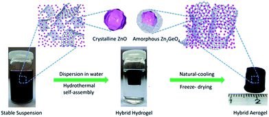
The preparation process can be described as consisting of three steps: (i) the GO powder, Zn(AC)2, Na2GeO3, and vitamin C were dissolved in DI water, respectively, to obtain stable precursor was formed by a mild wet chemistry reaction. (ii) The precursor was freeze-dried and yielded ZZGO/GA. The preparation of ZZGO/GA is schematically illustrated in Scheme 1.
The phase of samples was examined by X-ray diffraction (XRD) (Fig. 1a). The obvious sharp diffraction peaks of ZnO (JCPDS no. 36-1451) in the XRD diffraction pattern indicate that the ZnO phase is well-crystallized. The formation of ZnO was due to the preferential hydrolysis of zinc acetate. The broad diffraction peaks are at approximately 12.5° and 25° and correspond to amorphous Zn2GeO4 (JCPDS no. 11-0687). In order to further explore the structure and phase of the composite, the chemical bonds of [ZnO4]6− and [GeO4]4− in ZZGO were verified by Fourier transform infrared (FTIR) spectra. The stretching vibration of Ge–O bonds in A-ZGO led to a peak at around 820 cm−1, which confirmed the existence of the [GeO4]4− structure.28,29 The peak around 560 cm−1 is related to the Zn–O bonds in ZnO and Zn2GeO4 (Fig. 1b).30 The presence of GA is also confirmed by TGA analysis, and the total carbon weight fraction in the ZZGO/GA is around 42% (shown in Fig. S3 in the ESI†). All of the results are consistent with GA/ZZGO.
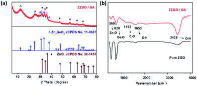 | ||
| Fig. 1 (a) X-ray diffraction patterns of ZZGO/GA and two standards. (b) FTIR spectra of pure ZGO and ZZGO/GA. | ||
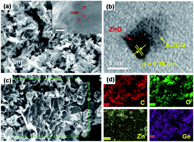
The microstructure of the as-prepared ZZGO/GA composite Fig. 2a reveals the interconnected 3D porous network of ZZGO/GA at different magnifications, in which graphene sheets are linked with each other and form a stable 3D structure, with ZZGO nanoparticles 10–20 nm in size distributed uniformly on the graphene sheets. Fig. 2c and d shows typical elemental mapping performed over the special 3D structure with respect to C, Ge, Zn, and O, which indicates that the ZnO and A-ZGO nanoparticles are well-dispersed in the 3D nanoarchitecture. Fig. 2b presents a high-resolution transmission electron microscope (HRTEM) image of the ZZGO/GA hybrid. It shows that the crystalline ZnO particle is wrapped by an amorphous Zn2GeO4 layer and forms a core–shell structure. It also can be seen that the lattice fringes are approximately 0.28 nm, which corresponds to the spacing of the (100) planes of hexagonal ZnO.
In order to investigate the electrochemical properties of the samples during the charge–discharge process, all the samples were assembled into coin-type half-cells. Fig. S4† shows the cyclic voltammetry (CV) curves of the ZZGO/GA, which were collected at a slow scan rate of 0.1 mV s−1 for the first 3 cycles in the potential window of 0.01–2.8 V versus Li+/Li. Usually, the second metal in alloy anodes and oxygen in metal-oxide anodes are introduced to form a buffer matrix to alleviate the damage caused by volume changes of the active materials. Unfortunately, in most cases, either the second metal is electrochemically inert with respect to lithium or the Li2O formed during the first lithiation process cannot be reversibly charged/discharged in the following cycles, leading to decreased reversible capacity of the whole anodic reaction. In our case, however, with the amorphous Zn2GeO4 layer, not only can zinc form zinc–lithium alloy reversibly, as demonstrated by a previous study on zinc-containing anode materials, but also the reactions between the oxides and lithium (ZnO + 2Li ↔ Zn + Li2O and GeO2 + 4Li ↔ Ge + 2Li2O) are at least partially reversible.31
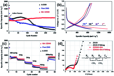
The cycling performance of the samples is presented in Fig. 3a. The ZZGO/GA electrode was tested at 100 mA h g−1 in the first two cycles in order to activate the batteries. High initial discharge and charge capacities of around 1536.9 and 941.1 mA h g−1 can be delivered, respectively. The first cycle coulombic efficiency (CE) was about 61% (Fig. S6†), and the average coulombic efficiency was nearly 100% from the second cycle, indicating stabilization of the solid electrolyte interphase (SEI) layer. It is the special structure of GA that ensured the stability of the electrode during charge/discharge. After activation, the electrode was tested at 500 mA g−1 for 250 cycles. Encouragingly, the composite electrode exhibited a high reversible capacity of 905 mA h g−1, demonstrating the excellent cycling stability and high capacity of the as-obtained ZZGO/GA graphene nanocomposite. When compared with the pure ZGO and amorphous ZGO, the ZZGO/GA anode exhibited much better cycling performance. The superior performance of the ZZGO/GA suggested high-efficiency synergistic effects between the three components in its structure. First of all, the core–shell structure, consisting of the amorphous and crystalline composite, can maintain lower volume expansion during lithiation and delithiation processes. Meanwhile, compared with pure ZGO and amorphous ZGO, the graphene sheets could restrain pulverization of the electrode from the alloying and leapfrog cracking.32,33 Furthermore, the 3D porous structure ensures the stability of the SEI layers, so as to decrease the pulverization of the electrode.23
The rate capability was tested at current densities of 0.5, 1, 2, 5, and 10 A g−1. The ZZGO/GA electrode exhibited a capacity of 908, 760.4, 553, 335, and 205 mA h g−1, respectively. When the current density was returned to 0.5 A g−1, the capacity could return to 896 mA h g−1 (Fig. 3c). Remarkably, the experiments showed that GA/ZZGO had better performance in the rate performance test compared to pure ZGO and A-ZGO, which may be due to three advantages. First, the 3D porous network guarantees more stable lithium ion transport channels. In addition, the amorphous structure provides some active sites and thus increases the capacity to some extent. Finally, the hierarchical structure and synergistic effects contribute to charge/discharge processes at high currents.34
In order to examine the Li diffusion kinetics of the ZZGO/GA anode, electrochemical impedance spectroscopy (EIS) was also applied to study the internal behavior of the as-prepared ZZGO/GA and pure ZGO electrodes. Fig. 3d presents the Nyquist curves of the two kinds of electrodes. The high-frequency zone was represents the contact resistance (Rf), and the diameter of the medium frequency semicircle corresponds to the charge-transfer resistance (Rct) of the electrode/electrolyte interface, while the low-frequency sloping straight line is equivalent to the Warburg impedance (Zw), which can be explained as the resistance to solid-state diffusion of lithium ions in the bulk electrode (Re). The results are given in Table 1. The core–shell structure and the 3D GA can suppress the volume changes, pulverization, and aggregation of these nanoparticles, and hence, the charge-transfer resistance Rct (Ω) of the ZZGO/GA hybrid is much smaller than that of the pure ZGO. Apart from this, the impedance slope of the electrode is much higher than for the pure ZGO, which indicates that there is a higher mobility of Li+ ions in the ZZGO/GA electrode. The fast Li+ and electron transport pathways which are provided by the 3D network are the key elements for lowering the resistance during charge and discharge of the electrode.
| Sample | Rf [Ω] | Rct [Ω] |
|---|---|---|
| ZZGO/GA | 71.5 | 85.4 |
| ZGO | 97.2 | 106.4 |
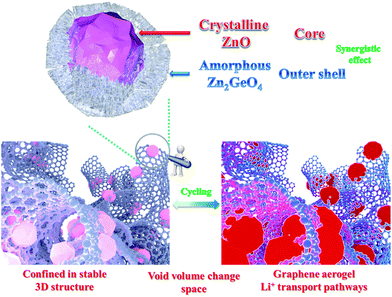
The excellent electrochemical performance of the ZZGO/GA electrode should be ascribed to the synergistic effects of our specially designed the structure, as shown in Fig. 4, which illustrates the electrochemical mechanisms of the ZZGO/GA electrode during charge/discharge. First, the active sites of the amorphous structure increase the performance to a certain degree. Second, the core–shell structure of ZZGO manifests lower volume expansion during cycling. Finally, the 3D network not only prevents pulverization of the materials, but also provides fast Li+ and electron transport pathways for the electrodes (Fig. S10†).
Conclusions
In summary, a three-dimensional crystalline–amorphous core–shell ZnO/Zn2GeO4/graphene aerogel structure has been successfully synthesized via a facile and mild solvothermal method by a self-assembly approach. Due to its superior hierarchical structure, the specific discharge capacity of 905 mA h g−1 was retained at a current density of 500 mA g−1 after 250 cycles, and the capacity retention was nearly 100%. In addition, this anode material also shows impressive rate capability of 205 mA h g−1 at the current density of 10 A g−1. We attribute the greatly enhanced electrochemical properties of ZZGO/GA to its stable three-dimensional hierarchical structure, the excellent electrical conductivity of its carbon aerogel network, and its low volume changes, making it a promising anode material for high-capacity LIBs.Conflicts of interest
The authors declare no competing financial interest.Acknowledgements
Financial support provided by a grant from the National Natural Science Foundation of China (No. 21476063) is gratefully acknowledged. The authors would like to thank Dr T. Silver for critical reading of the manuscript.Notes and references
- M. Armand and J. M. Tarascon, Nature, 2008, 451, 652 CrossRef CAS PubMed.
- P. G. Bruce, B. Scrosati and J. M. Tarascon, Angew. Chem., Int. Ed., 2008, 47, 2930 CrossRef CAS PubMed.
- F. Zou, X. Hu, L. Qie, Y. Jiang, X. Xiong, Y. Qiao and Y. Huang, Nanoscale, 2014, 6, 924–930 RSC.
- F. Zou, X. Hu, Z. Li, L. Qie, C. Hu, R. Zeng, Y. Jiang and Y. Huang, Adv. Mater., 2014, 26, 6622–6628 CrossRef CAS PubMed.
- Y. Zheng, T. Zhou, C. Zhang, J. Mao, H. Liu and Z. Guo, Angew. Chem., Int. Ed., 2016, 55, 3408–3413 CrossRef CAS PubMed.
- C. Zhang, X. Peng, Z. Guo, C. Cai, Z. Chen, D. Wexler, S. Li and H. Liu, Carbon, 2012, 50, 1897–1903 CrossRef CAS.
- J. Yang, T. Zhou, R. Zhu, X. Chen, Z. Guo, J. Fan, H. Liu and W. Zhang, Adv. Mater. Interfaces, 2016, 3, 1500464 CrossRef.
- T. Zhou, W. Pang, C. Zhang, J. Yang, Z. Chen, H. Liu and Z. Guo, ACS Nano, 2014, 8, 8323–8333 CrossRef CAS PubMed.
- W. Luo, Y. Wang, S. Chou, Y. Xu, W. Li, B. Kong, S. Dou, H. Liu and J. Yang, Nano Energy, 2016, 27, 255–264 CrossRef CAS.
- B. Zhang, J. Q. Huang and J. Kim, Adv. Funct. Mater., 2015, 25, 5222 CrossRef CAS.
- L. D. Lin, X. N. Xu and C. X. Chu, Angew. Chem., Int. Ed., 2016, 55, 14063 CrossRef CAS PubMed.
- G. KulbirKaur and S. C. Veer, J. Phys.: Condens. Matter, 2013, 25, 475501 CrossRef PubMed.
- E. Uchaker, Y. Z. Zheng, S. Li, S. L. Candelaria, S. Hu and G. Z. Cao, J. Mater. Chem. A, 2014, 2, 18208 CAS.
- Z. Y. Wang, D. Y. Luan, S. Madhavi, Y. Hu and X. W. Lou, Energy Environ. Sci., 2012, 5, 5252 CAS.
- T. Zhou, Y. Zheng, H. Gao, S. Min, S. Li, H. K. Liu and Z. P. Guo, Adv. Sci., 2015, 2, 1500027 CrossRef PubMed.
- H. Liu, W. Li, D. Shen, D. Zhao and G. Wang, J. Am. Chem. Soc., 2015, 137, 13161–13166 CrossRef CAS PubMed.
- C. Chen, H. Xu, T. Zhou, Z. Guo, L. Chen, M. Yan, L. Mai, P. Hu, S. Cheng, Y. Huang and J. Xie, Adv. Energy Mater., 2016, 6, 1600322 CrossRef.
- Z. Y. Wang, Z. C. Wang, W. T. Liu, W. Xiao and X. W. Lou, Energy Environ. Sci., 2013, 6, 87 CAS.
- C. Zhang, R. Yu, T. Zhou, Z. Chen, H. Liu and Z. Guo, Carbon, 2014, 72, 169–175 CrossRef CAS.
- B. Wang, W. A. Abdulla, D. l. Wang and X. S. Zhao, Energy Environ. Sci., 2015, 8, 869 CAS.
- R. H. Wang, C. H. Xu, M. Du, J. Sun, L. Gao, P. Zhang, H. L. Yao and C. C. Lin, Small, 2014, 10, 2260 CrossRef CAS PubMed.
- L. S. Fan, Y. Zhang, Q. Zhang, X. Wu, J. H. Cheng, N. Q. Zhang, Y. J. Feng and K. N. Sun, Small, 2016, 12, 5208 CrossRef CAS PubMed.
- H. Gao, T. Zhou, Y. Zheng, Y. Liu, J. Chen, H. Liu and Z. Guo, Adv. Energy Mater., 2016, 6, 1601037 CrossRef.
- Y. Xu, Z. Lin, X. Zhong, B. Papandrea, Y. Huang and X. Duan, Angew. Chem., Int. Ed., 2015, 127, 5435 CrossRef.
- S. Nardecchia, D. Carriazo, M. Ferrer, M. Gutierrez and F. Monte, Chem. Soc. Rev., 2013, 42, 794 RSC.
- J. Xu, M. Wang, N. Wickramaratne, M. Jaroniec, S. Dou and L. Dai, Adv. Mater., 2015, 27, 2042–2048 CrossRef CAS PubMed.
- W. Hummers and R. Offeman, J. Am. Chem. Soc., 1958, 80, 1339 CrossRef CAS.
- V. Koleva and D. Stoilova, J. Mol. Struct., 2002, 611, 1 CrossRef CAS.
- W. Liu, T. Zhou, Y. Zheng, J. Liu, C. Feng, Y. Shen, Y. Huang and Z. Guo, ACS Appl. Mater. Interfaces DOI:10.1021/acsami.7b00582.
- S. Takeshita, J. Honda, T. Isobe, T. Sawayam and S. Niikura, Cryst. Growth Des., 2010, 10, 4494 CAS.
- R. Yia, J. K. Feng, D. P. Lv, M. Gordin, S. R. Chen, D. Choi and D. H. Wang, Nano Energy, 2013, 2, 498 CrossRef.
- A. Kushima, X. Liu, G. Zhu, Z. Wang, J. Huang and J. Li, Nano Lett., 2011, 11, 4535 CrossRef CAS PubMed.
- F. Du, B. Li, W. Fu, Y. Xiong, K. Wang and J. Chen, Adv. Mater., 2014, 26, 6145–6150 CrossRef CAS PubMed.
- L. Hou, L. Lian, L. Zhang, G. Pang, C. Yuan and X. Zhang, Adv. Funct. Mater., 2015, 25, 238 CrossRef CAS.
Footnote |
| † Electronic supplementary information (ESI) available: Experimental procedures, XRD, Raman, TGA, XPS, CV, coulombic efficiency and SEM are available. See DOI: 10.1039/c7ra02259j |
| This journal is © The Royal Society of Chemistry 2017 |

