
 Open Access Article
 This Open Access Article is licensed under a
 Creative Commons Attribution 3.0 Unported Licence
Multi-walled carbon nanotubes induced a controllable TiO2 morphology transformation for high-rate and long-life lithium-ion batteries†
Yu Xiaa,
Wan-Sheng Xionga,
Yun Jianga,
Weiwei Sunb,
Hong-Qian Sanga,
Rong-Xiang Hea,
Qidong Taia,
Bolei Chena,
Yumin Liu *a and
Xing-Zhong Zhaoc
*a and
Xing-Zhong Zhaoc
aInstitute for Interdisciplinary Research, Key Laboratory of Optoelectronic Chemical Materials and Devices, Ministry of Education, Jianghan University, Wuhan 430056, China. E-mail: ymliu@jhun.edu.cn
bCollege of Aerospace Science and Engineering, National University of Defence Technology, Changsha, Hunan 410073, China
cSchool of Physics and Technology, Key Laboratory of Artificial Micro/Nano Structures, Ministry of Education, Wuhan University, Wuhan 430072, China
First published on 19th April 2017
Abstract
We have demonstrate a facile strategy to achieve the controllable morphology transformation of TiO2 induced by the introduction of multi-walled carbon nanotubes. The intervention of functionalized carbon nanotubes (CNTs) is key to the formation of TiO2 nanopompons. Furthermore, the size of the obtained TiO2 nanopompons can be controlled by modulating the CNT amounts. The obtained TiO2 nanopompon-embedded CNT hybrid networks (TNP@CNT HNs) incorporate the advantages of hierarchical nanostructures and 3D interconnected conductive networks, including high surface area, uniform particle/pore size, short Li+ ion/electron transport pathway, and high electronic conductivity. These TNP@CNT HN-based anodes achieve a significant improvement in the insertion/extraction of Li+ ions and electrochemical performances via optimizing the CNT amounts and the size of the TiO2 nanopompons. The lithium-ion batteries based on the optimized TNP@CNT HNs exhibit excellent cycling stability (keeping approximately 200 mA h g−1 after 500 cycles at 2C rate, 1C = 170 mA g−1) and rate performance (approximately 125 mA h g−1 at 20C rate with a capacity retention of 77% after 2000 cycles).
1. Introduction
Titanium dioxide (TiO2) has attracted considerable attention as one of the most credible alternative anode materials to conventional graphite, attributed to its low cost, environmental benignity, and high structural stability.1–3 Anatase-phase TiO2 has a relatively high insertion/extraction potential (1.3–1.8 V vs. Li+/Li) inhibiting common growth of Li dendrites on the anode surface, and a small volume expansion (less than 4%) during the Li+ insertion/extraction process ensuring good cycling stability.4 However, some inherent drawbacks impede the further development of anodes based on TiO2, such as the low ionic diffusivity and electronic conductivity.5,6 To address this issue, many efforts have been devoted to the synthesis of nanoscale TiO2 with a high electrode/electrolyte interface area and short solid state diffusion pathway for Li+ ions/electrons.7–10 Nevertheless, the increased contact resistance and inevitable self-aggregation caused by the use of nanosized TiO2 anode materials leads to eventual capacity fading and poor cycling stability.11,12 In this regard, hybrid structures combining TiO2 and carbon nanotubes (CNTs) have been proposed to circumvent the above problems.13–15CNTs with high electronic conductivity (approximately 5 × 10⁵ S m−1) can be well connected to form 3D conductive networks by π–π interactions, which provide continuous electron transport pathways and ensure fast penetration of the electrolyte.16 Furthermore, the 3D connected CNT networks also facilitate the dispersion of TiO2 nanostructures because of their large surface area and internal pore volume that preventing the self-aggregation of TiO2 anode materials during Li+ ion insertion/extraction process.17 As reported in previous literatures, numerous approaches have been proposed to synthesize TNP@CNT composites.18–20 Typically, it is difficult to control the hydrolysis rate of heterogeneous nucleation on graphite surface. Thus most reports were about disordered TiO2 nanoparticles or aggregations on CNTs. Recently, many strategies have been demonstrated to directly synthesize the coaxial core–shell heterostructures formed by coating TiO2 nanocrystal building blocks on the surface of CNTs.21–23 Generally, the formation of ultrathin TiO2 shell is essential to shorten Li+ ion diffusion length and guarantee sufficient electron transport, which results in relatively low active-material loading.24 Therefore, it is of great importance to design and synthesize uniform 3D TNP@CNT hybrid networks with well-defined morphology and homogeneous dispersion for achieving high electrochemical performance.
Herein, we demonstrate a controllable morphology transformation of TiO2 induced by CNTs, as shown in Fig. 1a. The intervention of functionalized CNTs not only promotes the formation of TiO2 nanopompons, but also provides an interconnected conductive network ensuring the homogenous dispersion of TiO2 and fast diffusion kinetics of both Li+ ions and electrons. Moreover, the relationship between the size of obtained TiO2 nanopompons and the concentration of CNTs in the precursor has been investigated. To our best of knowledge, this is the first time to report these 3D CNT hybrid networks with controllable uniform TiO2 nanopompon dispersion. The lithium-ion batteries based on these TNP@CNT HNs anode materials exhibit excellent cycling stability and rate performance, attributing to such unique hybrid architecture that combines the advantages of well-defined hierarchical nanostructures and 3D interconnected conductive networks.
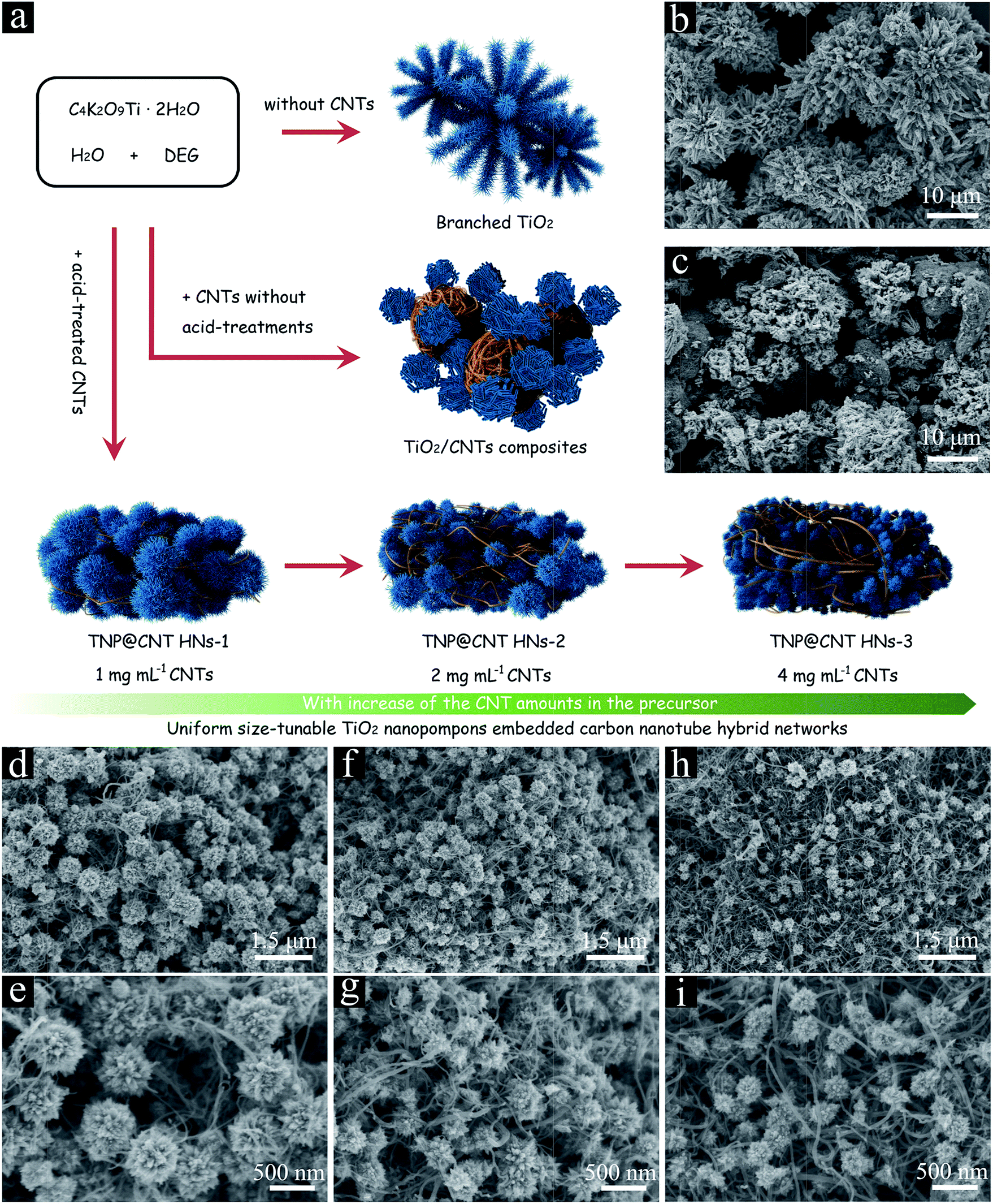 | ||
| Fig. 1 (a) Schematic representation of the controllable morphology transformation of TiO2 induced by precisely modulating the CNT amounts in the precursor. FE-SEM images of (b) branched TiO2 without CNTs, (c) TiO2/CNTs composites, (d and e) TNP@CNT HNs-1, (f and g) TNP@CNT HNs-2, and (h and i) TNP@CNT HNs-3. | ||
2. Experimental section
2.1 Synthesis of uniform TiO2 nanopompon embedded carbon nanotube hybrid networks
The uniform size-tunable TiO2 nanopompon embedded carbon nanotube hybrid networks (TNP@CNT HNs) were synthesized via a facile one-pot hydrothermal approach. Firstly, the functionalized multi-walled CNTs were obtained by nitric acid treatment at 120 °C for 5 h. Then, the acid-treated CNTs were ultrasonically dispersed in 10 mL deionized (DI) water, followed by adding 0.5 g potassium titanium oxide oxalate (PTO) and 30 mL diethylene glycol (DEG). In order to investigate the influence of CNTs on the morphology of as-synthesized TiO2, the concentration of CNTs in precursor DI water was controlled to 1, 2, and 4 mg mL−1, respectively. The obtained mixture solution was transferred to a 100 mL Teflon-lined autoclave and heated at 180 °C for 6 h. The resulting precipitate was recovered by centrifuging and rinsing with sufficient DI water several times to remove soluble impurities, followed by drying in vacuum at 70 °C over night. Subsequently, all the dried samples were annealed in a nitrogen atmosphere at 500 °C for 1 h. The final products obtained with 1, 2, and 4 mg mL−1 CNTs were labelled as TNP@CNT HNs-1, TNP@CNT HNs-2, and TNP@CNT HNs-3, respectively.For comparison purpose, TiO2/CNT composite was prepared by employing CNTs without any acid treatments according to the procedures described above (the concentration of CNTs is controlled to 2 mg mL−1). Branched TiO2 sample was also obtained via the mentioned synthetic process without the intervention of CNTs.
2.2 Material characterizations
XRD measurements were performed on a PANalytical XRD system with Cu Kα radiation (λ = 1.54056 Å). Raman spectra were recorded on a Renishaw inVia Laser micro-Raman spectrometer with an excitation of 532 nm laser light. The morphologies of uniform TNP@CNT HNs were observed using a field-emission scanning electron microscopy (FE-SEM, HITACHI SU8010). Transmission electron microscopy (TEM) and high-resolution TEM investigations were carried out on a FEI Tecnai G20. Thermo-gravimetric analysis (TGA) was performed on a SDT Q600 thermal analyzer (TA, USA), with a heating rate of 10 °C min−1 from room temperature to 800 °C in air. The specific surface area and pore size distribution of as-synthesized samples were characterized nitrogen adsorption–desorption isotherms (Micromeritics ASAP 2020 instrument). X-ray photoelectron spectroscopy (XPS) was performed on a multifunctional imaging electron spectrometer (Thermo ESCALAB 250XI) using monochromated Al Kα radiation (1486.6 eV).2.3 Electrochemical measurements
The working electrodes for the battery test cells were prepared from the active materials (TNP@CNT HNs), carbon black, and a polyvinylidene fluoride binder in a weight ratio of 70![[thin space (1/6-em)]](https://www.rsc.org/images/entities/char_2009.gif) :20:10, followed by pasting on a Cu foil and drying under vacuum at 120 °C overnight. The mass of active materials loaded on each electrode was ca. 0.5 mg. The electrochemical properties of the obtained TNP@CNT HNs samples were conducted using 2032 coin-type half cells that were assembled in a glove box filled with argon gas. A pure Li foil was employed as the counter electrode and a polypropylene membrane (Celgard) was used to separate the anode and cathode. The electrolyte consisted of a solution of 1.0 M LiPF6 in ethylene carbonate (EC), ethylene methyl carbonate (EMC) and dimethyl carbonate (DMC) (in a volume ratio of 1:1:1) obtained from Shenzhen Kejing Instrument Co. Ltd. A cyclic voltammograms (CV) test was performed on an electrochemical workstation (Zahner, Zennium) between 1.0 and 3.0 V at a scan rate of 0.1 mV s−1. The galvanostatic discharge and charge measurements were carried out on a LANHE test system (CT2001A) in a voltage range of 1.0–3.0 V vs. Li/Li+ at room temperature with different current rates. Electrochemical impedance spectroscopy (EIS) measurements were performed on a CHI660C electrochemical workstation.
:20:10, followed by pasting on a Cu foil and drying under vacuum at 120 °C overnight. The mass of active materials loaded on each electrode was ca. 0.5 mg. The electrochemical properties of the obtained TNP@CNT HNs samples were conducted using 2032 coin-type half cells that were assembled in a glove box filled with argon gas. A pure Li foil was employed as the counter electrode and a polypropylene membrane (Celgard) was used to separate the anode and cathode. The electrolyte consisted of a solution of 1.0 M LiPF6 in ethylene carbonate (EC), ethylene methyl carbonate (EMC) and dimethyl carbonate (DMC) (in a volume ratio of 1:1:1) obtained from Shenzhen Kejing Instrument Co. Ltd. A cyclic voltammograms (CV) test was performed on an electrochemical workstation (Zahner, Zennium) between 1.0 and 3.0 V at a scan rate of 0.1 mV s−1. The galvanostatic discharge and charge measurements were carried out on a LANHE test system (CT2001A) in a voltage range of 1.0–3.0 V vs. Li/Li+ at room temperature with different current rates. Electrochemical impedance spectroscopy (EIS) measurements were performed on a CHI660C electrochemical workstation.
3. Results and discussion
The morphologies of as-synthesized samples were characterized by field-emission scanning electron microscopy (FE-SEM), as shown in Fig. 1d–i. Uniform TiO2 nanopompon embedded carbon nanotube hybrid networks were obtained by controllable hydrolysis of potassium titanium oxide oxalate (PTO) via a facile one-pot hydrothermal process. The formed TiO2 nanopompons were monodispersed with a size of approximately 500 nm and dispersed uniformly between the CNTs, as shown in Fig. 1d and e. With the increase of CNT amounts, the size of obtained TiO2 nanopompons decreased to approximately 300 and 200 nm for TNP@CNT HNs-2 and TNP@CNT HNs-3 samples, as shown in Fig. 1f–i. In our contrast test, we synthesized micro-sized branched TiO2 assembled by nanowire-coated dendrites without addition of CNTs (Fig. 1b). Thus, the intervention of CNTs in this work promotes the formation of TiO2 nanopompons. The existence of CNTs not only hinders the directional growth of dendritic building blocks resulting to a nano-sized TiO2 architecture, but also provides an interconnected conductive network ensuring the homogenous dispersion of TiO2 and fast diffusion kinetics of both Li+ ions and electrons. In order to identify the growth patterns, we systematically investigated the influence of the reaction time to the TiO2 morphology transformation, as shown in Fig. S1.† The amount of CNTs for the set of experiments is 1 mg mL−1. It can be observed that there are few TiO2 nanostructures in a short reaction time (0.5 h and 1 h). When the reaction time increased to 2 h, we have obtained TiO2 spheres in the interconnected CNT networks. With further increase of reaction time, the semi-grown TiO2 nanopompons have been obtained at 4 h and 5 h. However, the dispersion is not homogeneous and the obtained TiO2 architectures are not well-defined compared with those synthesized at 6 h. Furthermore, we prepared TiO2/CNT composite by employing CNTs without any acid treatments according to the same procedures, as shown in Fig. 1c. It can be observed that the acid-treatment of CNTs is significant to the formation of well-defined 3D TiO2 morphology and homogeneous dispersion between CNTs.Fig. 2a shows the typical X-ray diffraction (XRD) patterns for as synthesized TNP@CNT HNs-1, TNP@CNT HNs-2, and TNP@CNT HNs-3 powder. The diffraction peaks observed at XRD patterns of all the three samples can be indexed to a dominant anatase phase (JCPDS card no. 71-1166). A weak peak at a 2θ of 29.5° indicates the existence of a tiny TiO2-B phase (JCPDS card no. 74-1940). The typical peak of CNTs also appeared at a 2θ of 43.2° in all the XRD patterns, which are consistent with previous published results.25 The relative diffraction intensity of CNT peak was slightly enhanced resulting from the increase of CNT amount in TNP@CNT HNs samples. The crystal structures of all TNP@CNT HNs samples were also characterized by Raman spectroscopy in the range of 100–2000 cm−1, as shown in Fig. 2b. The vibrational modes with strong intensities centered approximately at 149 (Eg), 199 (Eg), 390 (B1g), 512 (A1g), and 639 cm−1 (Eg) were observed in Raman spectra of TNP@CNT HNs-1, TNP@CNT HNs-2, and TNP@CNT HNs-3, indicating that all the three samples have dominant anatase phase.26 It can be also observed that an additional vibrational mode with relatively weak intensity located approximately at 289 cm−1 attributing to TiO2-B phase, which is consistent with XRD analysis. Furthermore, characteristic peaks of CNTs appeared at wavelengths of approximately 1346 and 1578 cm−1, which related to the disordered band (D band) and graphitic band (G band). The G band/D band ratio of TNP@CNT HNs-1, TNP@CNT HNs-2, and TNP@CNT HNs-3 was 1.076, 1.019, and 0.992, respectively. The obtained G band/D band ratio decreased with the increase of CNTs, which indicates the stronger interconnection between TiO2 and CNTs resulting from the formation of more disordered 3D hybrid networks.
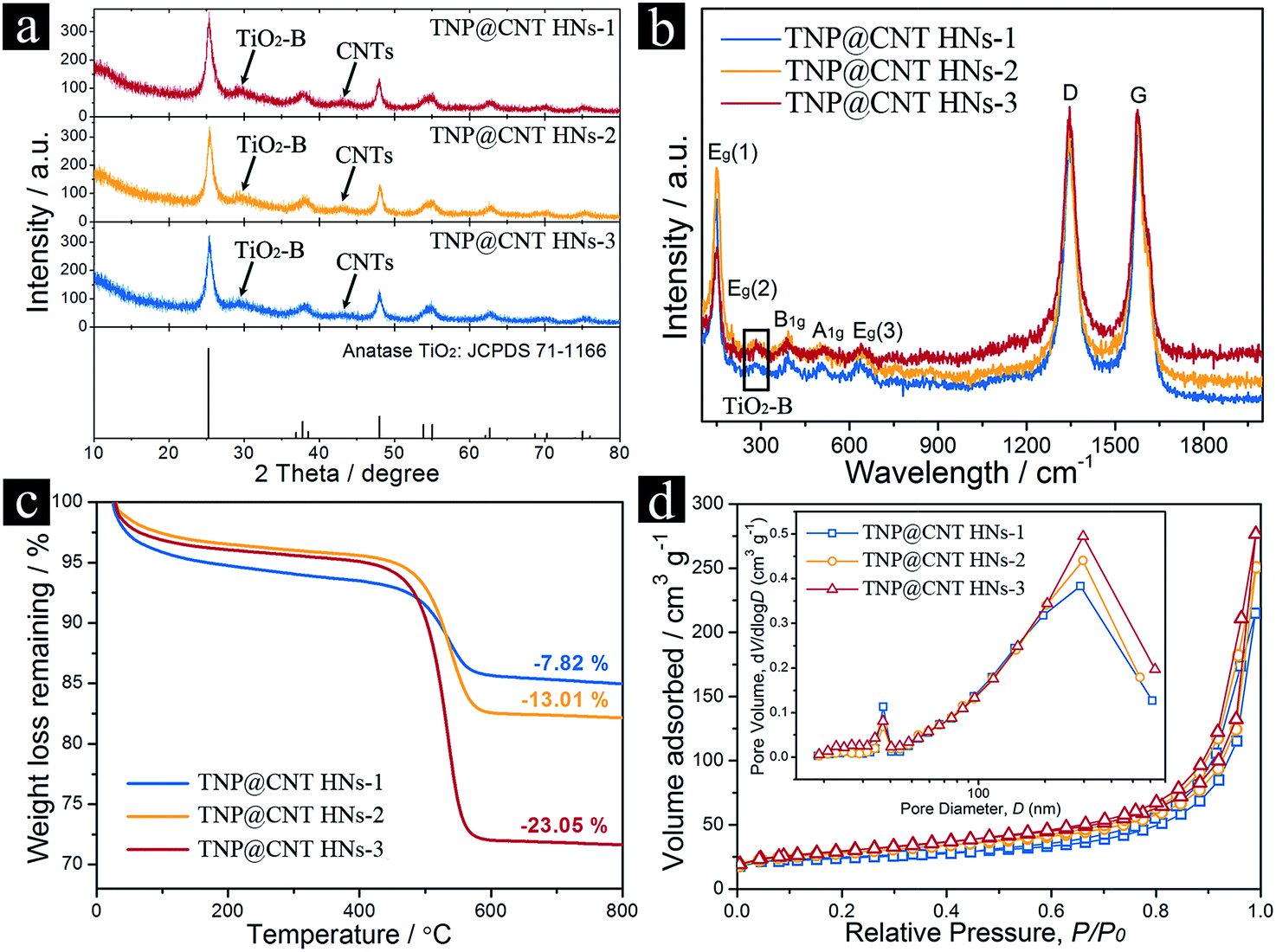 | ||
| Fig. 2 (a) X-ray diffraction patterns (Cu Kα radiation) of TNP@CNT HNs-1, TNP@CNT HNs-2, and TNP@CNT HNs-3. (b) Raman spectra of TNP@CNT HNs-1, TNP@CNT HNs-2, and TNP@CNT HNs-3 samples in the range of 100–2000 cm−1. (c) TGA curves for TNP@CNT HNs samples synthesized with different CNT amounts. (d) Nitrogen adsorption–desorption isotherm curves and pore-size distribution curves of TNP@CNT HNs-1, TNP@CNT HNs-2, and TNP@CNT HNs-3. | ||
The final content of CNTs in the hybrid composites were determined by thermo-gravimetric analysis (TGA) with a heating rate of 10 °C min−1 from room temperature to 800 °C in air, as shown in Fig. 2c. An obvious weight loss was observed from 450 to 600 °C in all the three samples resulting from the oxidation of CNTs. The weight percentages of CNTs in as-synthesized TNP@CNT HNs-1, TNP@CNT HNs-2, and TNP@CNT HNs-3 were 7.82%, 13.01%, and 23.05%, respectively. Textural characterizations of TNP@CNT HNs-1, TNP@CNT HNs-2, and TNP@CNT HNs-3 were investigated by nitrogen adsorption–desorption isotherms. All the three samples exhibited II-type isotherm curves with a type H3 hysteresis loop in the P/P0 range of 0.7–1.0,27 as shown in Fig. 2d. The observed II-type isotherms indicate the existence of macropores, and the type H3 hysteresis loop can be also attributed to a macropore size distribution tendency. The textural properties of all TNP@CNT HNs samples are summarized in Table 1. The Brunauer–Emmett–Teller (BET) surface area and total pore volume of TNP@CNT HNs-3 sample are 102.1 m2 g−1 and 0.4278 cm3 g−1, which are much higher than that of TNP@CNT HNs-1 and TNP@CNT HNs-2. The increased specific surface area and total pore volume are resulted from the size decrease of TiO2 nanopompons and the rise in CNT amounts. The pore size distribution calculated using the Barrett–Joyner–Halenda (BJH) method shows two sets of pores (Fig. 2d, inset). The pore size distribution centred at approximately 290 nm can be attributed to the formation of interconnected CNT hybrid networks. The secondary pore size at approximately 37 nm is probably ascribed to the TiO2 nanorods assembled 3D nanopompons.
| Samples | SBETa (m2 g−1) | Vtb (cm3 g−1) | Dpc (nm) |
|---|---|---|---|
| a SBET: the specific surface area calculated using the BET method.b Vt: the total pore volume at relative pressure (P/P0) of 0.99.c Dp: the pore diameter calculated from the desorption branch of the isotherm using the BJH method. | |||
| TNP@CNT HNs-1 | 80.9 | 0.3323 | 37.1, 289.1 |
| TNP@CNT HNs-2 | 95.5 | 0.3876 | 36.9, 296.7 |
| TNP@CNT HNs-3 | 102.1 | 0.4278 | 37.0, 297.5 |
The morphologies and crystalline structures of as-synthesized TNP@CNT HNs samples were further characterized by transmission electron microscopy (TEM), as shown in Fig. 3. The TEM images with low magnification confirmed the size decrease of TiO2 nanopompons with the increase of CNT amounts (Fig. 3a, e, and i). The obtained nanopompons were assembled by TiO2 nanorods of approximately 10–15 nm in diameter. Fig. 3b, f, and j show that the length of these TiO2 nanorods decreased from TNP@CNT HNs-1 to TNP@CNT HNs-3, confirming the inhibition effect of CNTs to the directional growth of TiO2 nanorods. The lattice fringes were clearly observed from high-resolution TEM images, as shown in Fig. 3c, g, and k. The neighboring lattice fringes with an interplane spacing of 3.51 ± 0.1 Å can be corresponding to (101) planes of anatase phase. Fig. 3d and h, and l show the electron diffraction patterns of TNP@CNT HNs samples. There are four diffraction rings that match well the (101), (103), (200), and (105) planes of anatase phase and two diffraction rings corresponding to (111) and (220) planes of TiO2-B, which is in good agreement with that characterization of XRD and Raman spectroscopy.
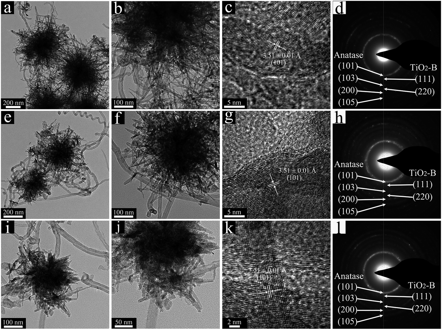 | ||
| Fig. 3 TEM and HR-TEM images of (a–c) TNP@CNT HNs-1, (e–g) TNP@CNT HNs-2, and (i–k) TNP@CNT HNs-3. (d), (h), and (l) show the electron diffraction patterns of corresponding sample. | ||
The chemical states of TNP@CNT HNs-2 were investigated by X-ray photoelectron spectroscopy (XPS). The XPS survey spectrum reveals that the sample is composed of Ti, C, O, and K elements, as shown in Fig. 4a. The two sets of peaks at 459.1 eV and 464.9 eV observed in Ti 2p spectrum can be associated to the Ti 2p3/2 and 2p1/2 binding energy (Fig. 4b), which are characteristic for the Ti4+ oxidation state. The high resolution XPS spectrum of C 1s reveals three types of carbon bonds (Fig. 4c). The main peak at 284.2 eV attributing to C–C, C![[double bond, length as m-dash]](https://www.rsc.org/images/entities/char_e001.gif) C or C–H indicates a conjugated honeycomb lattice of carbon atoms in the CNTs. The small peaks at 284.9 and 285.8 eV are related to the C–O and O–C–O bonds of carbon-based functional groups, respectively. As shown in Fig. 4d, the O 1s XPS spectra can be fitted into three peaks: Ti–O–Ti (530.5 eV), CO or OC–OH (531.0 eV), and Ti–O–C (eV). The existence of Ti–O–C bonds indicates that the TiO2 nanopompons are substantially bonded to the CNTs, which not only improved the electron transport but also stabilized the TNP@CNT hybrid structure.
C or C–H indicates a conjugated honeycomb lattice of carbon atoms in the CNTs. The small peaks at 284.9 and 285.8 eV are related to the C–O and O–C–O bonds of carbon-based functional groups, respectively. As shown in Fig. 4d, the O 1s XPS spectra can be fitted into three peaks: Ti–O–Ti (530.5 eV), CO or OC–OH (531.0 eV), and Ti–O–C (eV). The existence of Ti–O–C bonds indicates that the TiO2 nanopompons are substantially bonded to the CNTs, which not only improved the electron transport but also stabilized the TNP@CNT hybrid structure.
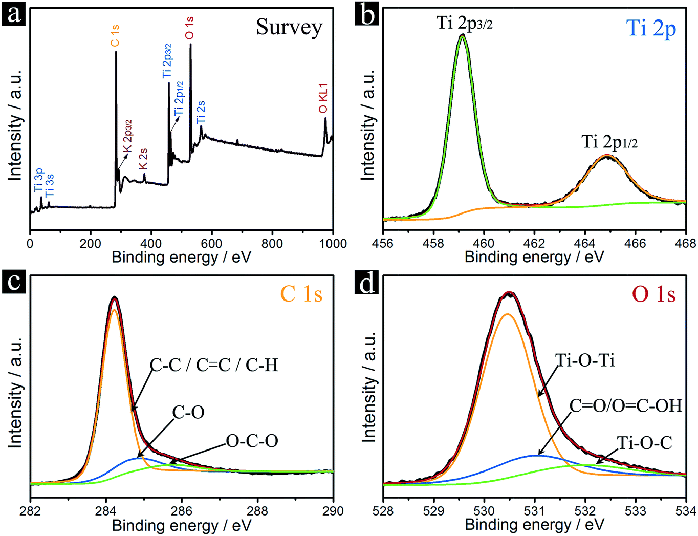 | ||
| Fig. 4 XPS patterns of the TNP@CNT HNs-2 sample. (a) Survey, (b) Ti 2p, (c) C 1s, and (d) O 1s. | ||
To evaluate the electrochemical performance of these TNP@CNT HNs, cyclic voltammograms (CV) of different samples for the initial cycle were performed in the voltage range from 1.0 to 3.0 V at a scan rate of 0.1 mV s−1, as shown in Fig. 5a. All the CV curves show a cathodic peak located at 1.75 V and a corresponding anodic peak centered at 2.0 V, which can be associated with Li+ ion insertion and extraction into and from the anatase lattice. It can be observed that the CV curves showed a slightly distorted rectangular shape in the range of 1.0–2.0 V, which can be associated to the characteristic of pseudocapacitive storage behavior resulting from the 3D TiO2 nanopompons and CNTs.4,21 Furthermore, the cathodic and anodic peaks of all the three samples are almost overlapping for the first three cycles (Fig. S2†), indicating that these TNP@CNT HNs have good reversibility. The lithium storage performances of LIBs based on these TNP@CNT HNs were investigated using a coin-type half-cell configuration with pure Li foil as the counter electrode at room temperature. Fig. 5b shows the cycling performances of LIBs based on TNP@CNT HNs-1, TNP@CNT HNs-2, and TNP@CNT HNs-3 electrodes at a rate of 2C (340 mA g−1) in the potential range of 1.0–3.0 V. The charge–discharge galvanostatic curves for all the three TNP@CNT HNs based anodes are shown in Fig. S3a–c.† The device based on TNP@CNT HNs-2 exhibited a high reversible capacity of 200 mA h g−1 after 500 cycles, whereas the LIBs based on TNP@CNT HNs-1 and TNP@CNT HNs-3 only retained a discharge capacity of 135 and 180 mA h g−1, respectively. The obviously enhanced reversible specific capacity of the TNP@CNT HNs-2 anode can be attributed to the optimization of introduced CNT amounts and the size of TiO2 nanopompons. An optimized uniform 3D TNP@CNT hybrid networks incorporated the advantages of hierarchical nanostructures and conductive interconnected networks, such as high surface area, uniform particle/pore size, short Li+ ion/electrons transport pathway, and high electronic conductivity. In order to confirm the superiority of this unique 3D hybrid architecture, we compared the cycling performance of TNP@CNT HNs-2 to those of TiO2/CNT composite and the branched TiO2 without CNTs, as shown in Fig. 5c. It can be observed that the capacity fading of the LIBs based on TiO2/CNT composite and branched TiO2 without CNTs is much higher than that of TNP@CNT HNs-2 based device. The battery based on TiO2/CNT composite delivered a discharge capacity of 131.2 mA h g−1 after 500 cycles, a 34.4% decrease compared to that of TNP@CNT HNs-2 based device. Thus, the acid-treatment of CNTs, which promoted to the formation of uniform TiO2 nanopompons embedded CNT hybrid networks, is significant to achieve an enhanced electrochemical performance. Without adding CNTs, we obtained branched TiO2 architecture. Although this 3D branched TiO2 architecture assembled by nanowire-coated TiO2 dendrites achieved remarkably improved electrochemical performance that has been reported in our previous work,7 the corresponding battery only obtained a discharge capacity of 141.9 mA h g−1 over 500 cycles. This result indicates that it is essential to design and synthesize proper TNP@CNT hybrids for achieving high electrochemical performance.
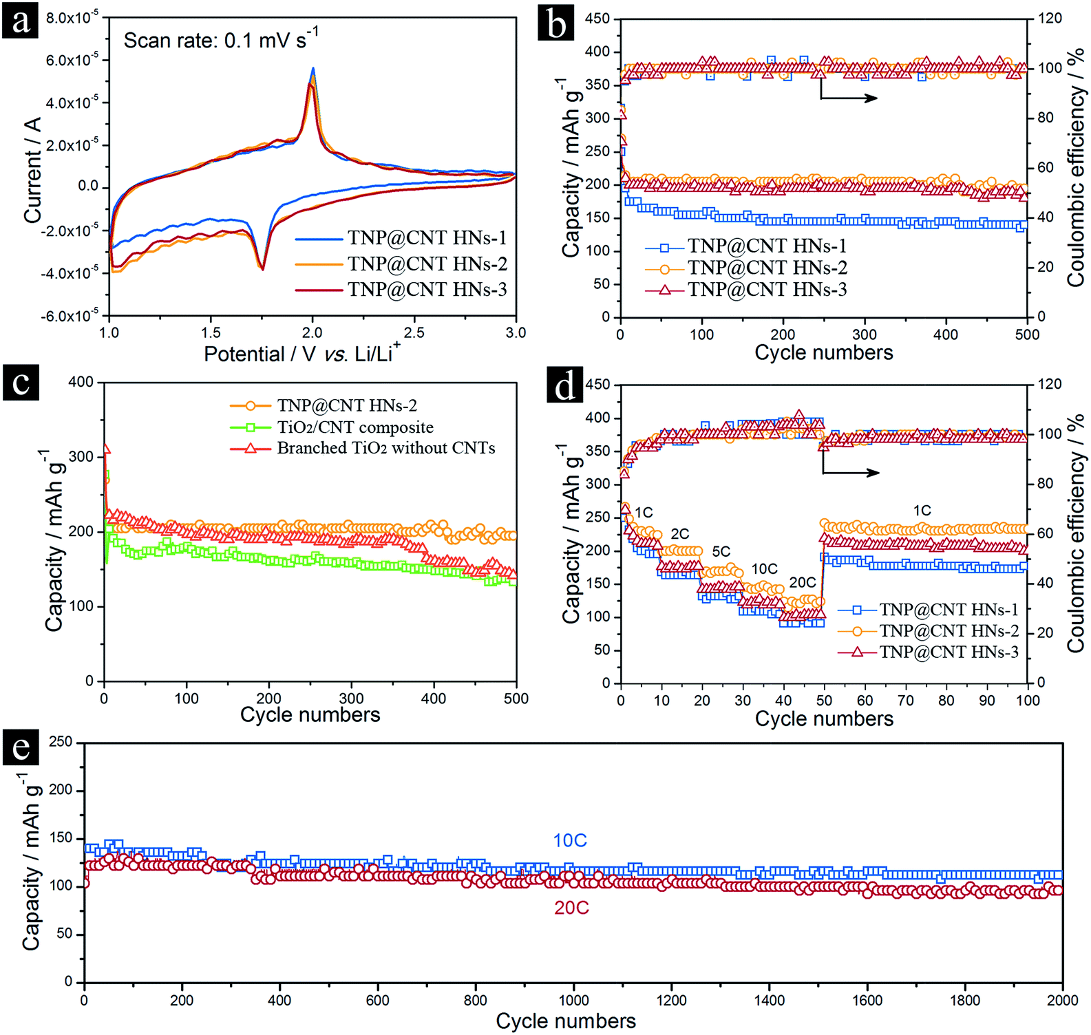 | ||
| Fig. 5 (a) Cyclic voltammograms of different TNP@CNT HNs samples for the initial cycle at a scan rate of 0.1 mV s−1 in the voltage range from 1.0 to 3.0 V. (b) Cycling performance of LIBs based on TNP@CNT HNs-1, TNP@CNT HNs-2, and TNP@CNT HNs-3 at a current rate of 2C (340 mA g−1). (c) Comparison of cycling performance for LIBs based on TNP@CNT HNs-2, TNP@CNT composites, and branched TiO2 without CNTs at a current rate of 2C (340 mA g−1). (d) Rate performance of TNP@CNT HNs-1, TNP@CNT HNs-2, and TNP@CNT HNs-3 electrodes cycled at different current rates from 1C (170 mA g−1) to 20C (3.4 A g−1). (e) Long-term cycle life of LIBs based on TNP@CNT HNs-2 at constant current rate of 10C (1.7 A g−1) and 20C (3.4 A g−1), respectively. | ||
To further investigate the rate capability of these TNP@CNT HNs, the batteries were charged and discharged under various rate conditions. Fig. 5d shows the rate performances of TNP@CNT HNs-1, TNP@CNT HNs-2, and TNP@CNT HNs-3 electrodes cycled at different current rates from 1C (170 mA g−1) to 20C (3.4 A g−1) between 1.0 and 3.0 V with the same charge and discharge rates. Comparison of the rate capability for all the three samples with increasing rates is shown in Fig. S3d–f.† The device based on TNP@CNT HNs-2 delivered a discharge capacity of approximately 224.2, 200.0, 169.7, 145.5, and 127.3 mA h g−1 at a rate of 1, 2, 5, 10, and 20C, respectively. In comparison, the batteries based on other two TNP@CNT HNs samples exhibited lower cycling capacity and more obviously degradation with increased current rates. The improved high rate performance of device based on TNP@CNT HNs-2 compared to the counterpart based on TNP@CNT HNs-1 can be attributed to the increased CNT amounts which provided more conductive interconnected networks. On the other side, the faded rate capability of TNP@CNT HNs-3 compared to that of TNP@CNT HNs-2 can be ascribed to the further decreased TiO2 nanopompon size resulting to a degree of self-aggregation. Therefore, it is essential to balance the introduced CNT amounts and obtained TiO2 nanopompon size. The capacity retention of TNP@CNT HNs-2 at high current rate was evaluated by cycling at a rate of 10C (1.7 A g−1) and 20C (3.4 A g−1) with the same charge and discharge rates for 2000 cycles. As shown in Fig. 5e, approximately 80% of its initial capacity (140 mA h g−1) was retained after 2000 cycles at 10C rate. Even at 20C rate, the battery achieved approximately 125 mA h g−1 with a capacity retention of 77% after 2000 cycles, revealing an excellent rate performance for long-term cycle life.
The electrochemical impedance spectroscopy (EIS) of these TNP@CNT HNs based LIBs was measured to get further insight into the diffusion kinetics of Li+ ion and electrons. Fig. 6a–c illustrate the Nyquist plots of TNP@CNT HNs-1, TNP@CNT HNs-2, and TNP@CNT HNs-3 based batteries before initial cycle, after 100 cycles and after 500 cycles at 2C rate (340 mA g−1) between 1.0 and 3.0 V. An equivalent circuit was used to fit the data of Nyquist plots (Fig. 6d), where Re is the resistance of electrolyte and cell components, R(sf+ct) is the resistance of Li+ migration through the surface and charge transfer, Rb is the bulk resistance, CPE(sf+ct) is the constant phase elements of surface film and double layer capacitance, CPEb is the bulk capacitance, Zw is the Warburg impedance, and Cint is the intercalation capacitance.28 The fitting results determined from EIS are also listed in the table shown in Fig. 6d. The battery based on TNP@CNT HNs-3 achieved the lowest value of R(sf+ct) for fresh cell and after cycles. The value of R(sf+ct) decreased with the rise of CNT amounts indicating the improved electronic contact and more effective charge transport after the introduction of CNTs. The schematic illustration of the lithium insertion and extraction process of the TNP@CNT HNs is shown in Fig. 6e. The formation of uniform 3D conductive interconnected networks incorporating with TiO2 nanopompons provide a high contact area with electrolyte and a short Li+ ion/electrons diffusion pathway. Therefore, this unique hybrid structure achieved a high specific rate capability and superior long-term cycling performances.
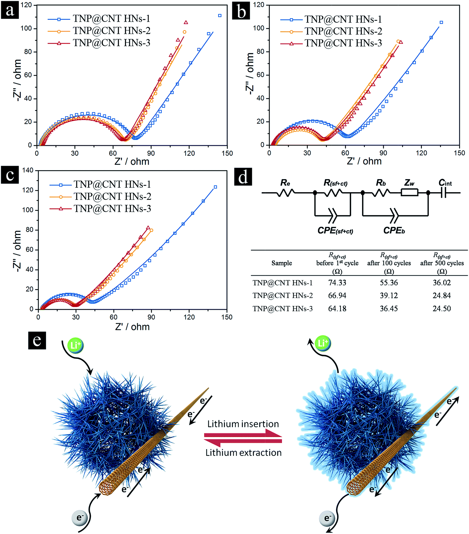 | ||
| Fig. 6 Nyquist plots of TNP@CNT HNs-1, TNP@CNT HNs-2, and TNP@CNT HNs-3 based batteries (a) before initial cycle, (b) after 100 cycles and (c) after 500 cycles at 2C rate (340 mA g−1) between 1.0 and 3.0 V. The symbols and the solid lines are the experimental data and the fitted results, respectively. (d) The equivalent circuit used to fit the Nyquist plots and the list of fitting results. (e) Schematic illustration of the lithium insertion and extraction process of the TNP@CNT HNs. | ||
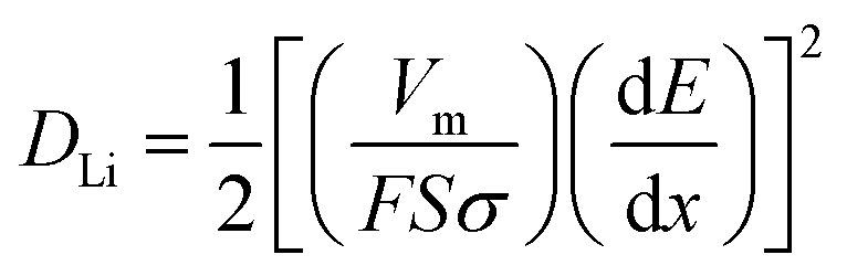
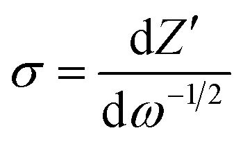
In order to further identify the structure–property relationship, we investigated the lithium diffusion coefficients (DLi) of the electrode materials, which can be determined by the Warburg data of Nyquist plots in the low-frequency region, according to the following equation:29
The calculated lithium diffusion coefficients of different TNP@CNT HN samples before initial cycle, after 100 cycles, and after 500 cycles are listed in Table S1.† It can be seen that the lithium diffusion coefficient was remarkable enhanced with the increase of CNT amounts, which can be attributed to the high conductivity of CNTs and the formation of interconnected networks. It is noteworthy that the DLi of TNP@CNT HNs-3 is the highest of all the three samples, however, the battery performance is not the best of all. Thus, there is a balance between the conductivity and the electrochemical performance. This result confirms the facile electron transport and Li+ diffusion between TNP@CNT HNs based anode materials and liquid electrolyte, which is consistent with the EIS analysis.
4. Conclusions
In summary, we have achieved a controllable morphology transformation of TiO2 via the introduction of CNTs. The relationship between the TiO2 nanopompon size and the CNT amounts in the precursor has been systematically investigated. The intervention of acid-treated CNTs promotes the formation of TiO2 nanopompons with tunable size from ∼200 to ∼500 nm by adjusting the amount of CNTs. Furthermore, the existence of CNTs provides an interconnected conductive network ensuring the homogenous dispersion of TiO2 and fast diffusion kinetics of both Li+ ion/electrons. Typically, the TNP@CNT HNs with an optimized diameter (∼300 nm) exhibited a high specific surface area, uniform particle/pore size, short Li+ ion/electrons transport pathway, and high electronic conductivity. Owing to these unique structural features, the LIBs based on this optimized TNP@CNT HNs shows excellent cycling performance and high rate capability. This interventional synthesis strategy opens up new opportunities to design and synthesize uniform 3D hybrid networks with well-defined morphology and homogeneous dispersion for achieving high electrochemical performance.Acknowledgements
This project was supported by the National Natural Science Foundation of China (Grant No. 61404060, No. 21403089, No. 81402466, No. 11547243, and No. 91433203). We would also like to acknowledge the financial support by Wuhan Youth Science and Technology Program.Notes and references
- S.-T. Myung, M. Kikuchi, C. S. Yoon, H. Yashiro, S.-J. Kim, Y.-K. Sun and B. Scrosati, Energy Environ. Sci., 2013, 6, 2609–2614 CAS.
- L.-P. Yang, X.-J. Lin, X. Zhang, W. Zhang, A.-M. Cao and L.-J. Wan, J. Am. Chem. Soc., 2016, 138, 5916–5922 CrossRef CAS PubMed.
- H. Ren, R. B. Yu, J. Y. Wang, Q. Jin, M. Yang, D. Mao, D. Kisailus, H. J. Zhao and D. Wang, Nano Lett., 2014, 14, 6679–6684 CrossRef CAS PubMed.
- N. T. H. Trang, Z. Ali and D. J. Kang, ACS Appl. Mater. Interfaces, 2015, 7, 3676–3683 Search PubMed.
- V. Etacheri, J. E. Yourey and B. M. Bartlett, ACS Nano, 2014, 8, 1491–1499 CrossRef CAS PubMed.
- G. Liu, L.-C. Yin, J. Pan, F. Li, L. Wen, C. Zhen and H.-M. Cheng, Adv. Mater., 2015, 27, 3507–3512 CrossRef CAS PubMed.
- S. F. Wang, D. D. Qu, Y. Jiang, W.-S. Xiong, H.-Q. Sang, R.-X. He, Q. D. Tai, B. L. Chen, Y. M. Liu and X.-Z. Zhao, ACS Appl. Mater. Interfaces, 2016, 8, 20040–20047 CAS.
- H. Hu, L. Yu, X. H. Gao, Z. Lin and X. W. Lou, Energy Environ. Sci., 2015, 8, 1480–1483 CAS.
- H. Y. Wang, J. Z. Chen, F.-X. Xiao, J. W. Zheng and B. Liu, J. Mater. Chem. A, 2016, 4, 6926–6932 CAS.
- J. Tian, Z. H. Zhao, A. Kumar, R. I. Boughton and H. Liu, Chem. Soc. Rev., 2014, 43, 6920–6937 RSC.
- G. Q. Zhang, H. B. Wu, T. S. Song, U. Y. Paik and X. W. Lou, Angew. Chem., Int. Ed., 2014, 53, 12590–12593 CAS.
- Q. H. Tian, Y. Tian, Z. X. Zhang, C. S. Qiao, L. Yang and S.-I. Hirano, J. Mater. Chem. A, 2015, 3, 10829–10836 CAS.
- L. F. He, C. D. Wang, X. L. Yao, R. G. Ma, H. K. Wang, P. R. Chen and K. Zhang, Carbon, 2014, 75, 345–352 CrossRef CAS.
- X. Sun, M. Xie, J. J. Travis, G. K. Wang, H. T. Sun, J. Lian and S. M. George, J. Phys. Chem. C, 2013, 117, 22497–22508 CAS.
- Y. C. Zhang, C. Guerra-Nuñez, M. Li, J. Michler, H. G. Park, M. D. Rossell, R. Erni and I. Utke, Chem. Mater., 2016, 28, 3488–3496 CrossRef CAS.
- E. A. Whitsitt and A. R. Barron, Nano Lett., 2003, 3, 775–778 CrossRef CAS.
- J. Wang, R. Ran, M. O. Tade and Z. P. Shao, J. Power Sources, 2014, 254, 18–28 CrossRef CAS.
- P. Zhang, J. X. Qiu, Z. F. Zheng, G. Liu, M. Ling, W. Martens, H. H. Wang, H. J. Zhao and S. Q. Zhang, Electrochim. Acta, 2013, 104, 41–47 CrossRef CAS.
- Y. K. Tang, L. Liu, X. C. Wang, D. Z. Jia, W. Xia, Z. B. Zhao and J. S. Qiu, J. Power Sources, 2016, 319, 227–234 CrossRef CAS.
- K. Hemalatha, A. S. Prakash, K. Guruprakash and M. Jayakumar, J. Mater. Chem. A, 2014, 2, 1757–1766 CAS.
- Y. Liu, A. A. Elzatahry, W. Luo, K. Lan, P. F. Zhang, J. W. Fan, Y. Wei, C. Wang, Y. H. Deng, G. F. Zheng, F. Zhang, Y. Tang, L. Q. Mai and D. Y. Zhao, Nano Energy, 2016, 25, 80–90 CrossRef CAS.
- M. C. Zou, Z. M. Ma, Q. F. Wang, Y. B. Yang, S. T. Wu, L. S. Yang, S. Hu, W. J. Xu, P. C. Han, R. Q. Zou and A. Y. Cao, J. Mater. Chem. A, 2016, 4, 7398–7405 CAS.
- L. T. Yan, Y. Xu, M. Zhou, G. Chen, S. G. Deng, S. Smirnov, H. M. Luo and G. F. Zou, Electrochim. Acta, 2015, 169, 73–81 CrossRef CAS.
- Z. Chen, D. Q. Zhang, X. L. Wang, X. L. Jia, F. Wei, H. X. Li and Y. F. Lu, Adv. Mater., 2012, 24, 2030–2036 CrossRef CAS PubMed.
- C.-T. Hsieh, Y.-C. Chen, Y.-F. Chen, M. M. Huq, P.-Y. Chen and B.-S. Jang, J. Power Sources, 2014, 269, 526–533 CrossRef CAS.
- X. F. Du, Q. W. Wang, T. Y. Feng, X. Z. Chen, L. Li, L. Li, X. F. Meng, L. L. Xiong, X. F. Sun, L. Lu and Y. L. Xu, Sci. Rep., 2016, 6, 20138 CrossRef CAS PubMed.
- M. Kruk and M. Jaroniec, Chem. Mater., 2001, 13, 3169–3183 CrossRef CAS.
- L. Xin, Y. Liu, B. J. Li, X. Zhou, H. Shen, W. X. Zhao and C. L. Liang, Sci. Rep., 2014, 4, 4479 Search PubMed.
- Y. Q. Zhang, Q. Fu, Q. L. Xu, X. Yan, R. Y. Zhang, Z. D. Guo, F. Du, Y. J. Wei, D. Zhang and G. Chen, Nanoscale, 2015, 7, 12215–12224 RSC.
Footnote |
| † Electronic supplementary information (ESI) available: CV curves of different TNP@CNT HNs for the first three cycles, the charge–discharge galvanostatic curves under different cycles and current rates. See DOI: 10.1039/c7ra02190a |
| This journal is © The Royal Society of Chemistry 2017 |