 Open Access Article
A high performance wire-shaped flexible lithium-ion battery based on silicon nanoparticles within polypyrrole/twisted carbon fibers†
Jiangyu Raoa,
Nishuang Liua,
Luying Lia,
Jun Sua,
Fei Longb,
Zhengguang Zou*b and
Yihua Gao *a
*a
aCenter for Nanoscale Characterization & Devices (CNCD), Wuhan National Laboratory for Optoelectronics (WNLO), School of Physics, Huazhong University of Science and Technology (HUST), Luoyu Road 1037, Wuhan 430074, P. R. China. E-mail: gaoyihua@hust.edu.cn
bSchool of Material Science & Engineering, Guangxi Nonferrous Metals Mineral and Materials, Collaborative Innovation Center, Guilin University of Technology, Jian'gan Road 12, Guilin 541004, Guangxi, P. R. China. E-mail: zouzg@glut.edu.cn
First published on 17th May 2017
Abstract
Currently, mechanically flexible and strong batteries are desired for the development of bendable and portable devices. To meet this requirement, a simple and scalable synthesis of the anode for flexible wire-shaped lithium-ion batteries has been developed by a facile one-step in situ polymerization method. Polypyrrole was found to grow on the surface of Si nanoparticles and attach to twisted carbon fibers. The formed cross-linked structure of Si/PPy along with carbon fiber substrate offers a consecutive electron transport network and a porous structure to adjust large volumetric changes of Si particles during charging and discharging processes. On fabricating the wire-shaped Li-ion battery, the interconnected Si/PPy/CF hybrid electrode was found to offer an excellent performance of 3.9% capacity decrease after the flexibility test, a greatly improved cycling capacity of 2287 mA h g−1 and a capacity retention of about 75% after 100 cycles of the half-cell test. The all-wet methodology may provide a promising route for a new scalable way to produce applicable wire-shaped electrode in battery fabrication.
1. Introduction
Currently, continuous progress in the improvement of portable electronic, medical devices, wearable devices, next generation of virtual-reality/augment-reality equipment and various flexible consumer products has been investigated by various companies.1 However, the traditional shapes and designs of energy-supplying systems may limit these creative applications due to their undeformable characteristics. To achieve this goal, next-generation energy storage devices must have light, flexible and small units with shape-conformability, aesthetic diversity and excellent mechanical properties.2 The key challenges in achieving the goal are the designing of suitable current collectors with good mechanical properties and fabrication of these flexible electrode materials with high specific capacity and excellent electrical conductivity.3After the cable/wire type lithium ion battery (LIB) was first introduced by Je Young Kim et al.,4 highly coaxial flexible cable-type LIB received extensive attention. Subsequently Peng et al. creatively designed the wire-type LIB using ultralong aligned multi-wall carbon nanotubes (MWCNTs) coated with silicon,5 Li4Ti5O12,6 and MnO2.7 These types of LIBs provide the innovative ideas for devices calling for excellent flexibility and lead the trends for wire-type/cable-type batteries beyond traditional craft technologies. The unique characteristics enable the applications in fabric and may even lead to new developments in wearable devices. However, the existing anodes of these LIBs were not suitable for mass production,5–7 and the rate capability of the cable-type LIB was not satisfactory. Therefore, the factors leading to a rapid discharge capacity loss of the battery need to be studied in detail.8 Thus, there is an immense need to design devices that provide the combination of high performance and economic cost.
Silicon, as a promising anode material, displays the following prominent features: (1) higher theoretical capacity (ca. 3579 mA h g−1) compared to commercial graphite (ca. 372 mA h g−1); (2) it is second-most abundant element on Earth; (3) environmental friendliness. Unfortunately, the huge volumetric expansion (ca. 400%) and unstable solid–electrolyte interface (SEI) during Li–Si alloying/dealloying process leads to rapid capacity decrease of the existing battery.8–13 In addition, poor conductivity and mechanical stability impede the transfer of carriers and reduce the rate capability of the electrode.14 It can be noted that carbonaceous material and conducting polymer (PANi,15,16 PEDOT17,18 and PPy19–25) perform well in terms of conductivity, mechanical and cycle stability but fall short of capacity. Currently, electrodes made from Si nanoparticles (SiNPs), carbonaceous material and conducting polymer have been studied as a potential asset in various syntheses routes combining their individual advantages by microwave plasma chemical vapor deposition method,22 electrospray,24 electrospinning23–25 and so on.26–29 Among the listed methods, in situ polymerization method has been considered as an ideal route to bond two types of materials firmly without a binder16,17,19,20 and form an interconnected structure thereby allowing efficient transfer of mass and electrons and efficient contact between the electrode and electrolyte. To the best of our knowledge, although carbonaceous material/Si and PPy/Si composite materials have been explored for their conventional planar structures and one-dimensional structures, they have not been investigated for ternary wire-shaped electrodes or batteries, particularly with commercial, low-cost carbon fibers (CFs).
Developing the PPy-based electrode, we originally demonstrated a novel one-step in situ approach to fabricate 1D fiber-based anode, Si/PPy/CFs with a 3D twisted nanostructure. The bi-functional conformal coating of PPy layer bound to Si surface served as a binder for Si and CFs, thereby preventing the large volume changes of Si and aggregation of nanoparticles. Combining with the highly conductive CFs substrate, it can also result into a porous interconnected nanostructure electrode and act as continuous 3D pathways for electron transportation. Moreover, the unique structure offers a porous 3D network increasing the electrolyte–electrode surface area. The as-prepared anode, separator and lithium wire were packed in a polymer tube. All of the mentioned intriguing peculiarities can effectively and simultaneously motivate high specific capacity, good cycle characteristics and rate capability of the battery. In addition, the all-solution-based method comes up with an underlying scalable preparation approach towards the industrial production of battery electrode.
2. Experimental
Reagents
Pyrrole monomer, isopropyl alcohol (IPrOH), phytic acid, and ammonium persulphate were purchased from Sinopharm Chemical Reagent Co., Ltd. (in Shanghai, P. R. China). Silicon nanoparticles were purchased from Alfa, Aesar Co., Ltd (in Tianjin, P. R. China). The 0.2 mm CFs were purchased from Tansuo Composites Co., Ltd (in Dongguan, P. R. China).Preparation of carbon fibers
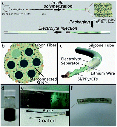
The typical preparation process of 1D CF-based hybrid anode has been schematically shown in Fig. 1a. First, the CFs were cut into several parts. Each part was about 50 mm in length and painted PDMS (RTV615, Momentive Co., Ltd) on both ends to avoid dispersion during cleaning steps. Then, CFs were treated with oxygen plasma (PDC-MG, Hengxin Co., Ltd) for 10 min and then immersed in HNO3 (90% wt) for 24 hours in order to attain hydrophilic nature for further treatment. Afterwards, they were cleaned with ethanol and deionized water a few times, followed by drying at 80 °C in an oven for 12 hours.Synthesis of Si/PPy/CF hybrid electrodes
Si/PPy/CFs hybrid electrodes were produced via in situ polymerization method similar to a reported method.19 8.4 mL pyrrole monomer and 200 mL phytic acid solution were mixed with 250 mL IPrOH to form a solution A. Solution B was prepared by dissolving 5.84 g ammonium persulphate into 50 mL deionized water. Furthermore, 75 mL solution A and 25 mL solution B were added into 300 mg SiNPs and thoroughly mixed at room temperature (20 °C) and ultra-sonicated for 10 min to produce a homogeneous silicon–polypyrrole hydrogel. Moreover, the cleaned CFs were added into hydrogel and ultra-sonicated for 15 min to form a homogeneous hybrid electrode. Finally, the coated CFs were air-dried for 2 h and then immersed in deionized water for 10 h to completely remove excess phytic acid and inorganic salts. Finally, they were dried at 80 °C in a vacuum oven for 12 h.Preparation of wire-shaped half cells
A silicone tube was used as a protecting and packaging layer for the half cell. A separator (Celgard 2400 films) was tailored, which was 45 mm in length and 2–3 mm in width. Then, Si/PPy/CFs electrode, two slices of separator, and lithium metal were carefully inserted into the tube in sequence. Each of the electrodes had a copper wire linked for the further test. Afterwards, we sealed one end with polydimethylsiloxane, injected the electrolyte into the tube and sealed the other end by polydimethylsiloxane. All cells were assembled in an argon-filled glove box with its moisture and oxygen lower than 1 ppm. The cells used lithium metal as the negative electrode. The electrolyte was a 1 M solution of LiPF6 in 1![[thin space (1/6-em)]](https://www.rsc.org/images/entities/char_2009.gif) :
:![[thin space (1/6-em)]](https://www.rsc.org/images/entities/char_2009.gif) 1 vol/vol mixture of ethylene carbonate (EC) and diethylcarbonate (DEC) with 10 wt% fluoroethylene carbonate (FEC, 98% purity, Aladdin) as an additive. The packed wire-shaped LIB is shown in Fig. 1f.
1 vol/vol mixture of ethylene carbonate (EC) and diethylcarbonate (DEC) with 10 wt% fluoroethylene carbonate (FEC, 98% purity, Aladdin) as an additive. The packed wire-shaped LIB is shown in Fig. 1f.
Characterization of materials
Scanning Electron Microscope (SEM, FEI Nova Nano-SEM 450) and Transmission Electron Microscope (TEM, FEI Tecnai G2 T20) were used to examine the morphologies of Si/PPy/CFs. To better understand the performance and make use of flexibility of the anode, electrochemical tests of Si/PPy/CFs electrodes versus Li/Li+ were carried out using homemade wire-shaped half cells, as shown in Fig. 1c. The galvanostatic charge/discharge measurements, rate performance and constant-capacity cycling tests were conducted using a LAND Battery Testing System at room temperature. The electrochemical impedance spectroscopy (EIS) and cyclic voltammetry (CV) were measured by an electrochemical workstation (Autolab, Metrohm). To investigate the structural evolution upon cycling, the electrodes were rinsed with acetonitrile overnight to wash off the residual electrolyte and then cleaned using aqueous solution of acetic acid (1 mM) to remove the solid electrolyte interface (SEI) layer and other impurities. Finally, each electrode was soaked in deionized water before the SEM experiment. All the tests were conducted in air atmosphere.3. Results and discussion
To obtain the interconnected 3D Si/PPy/CFs electrode, as schematically represented in Fig. 1, pyrrole (monomer) and phytic acid (the crosslinker and adulterant) were first added into the IPrOH solution and then stirred until the mixture appeared to be ivory white in color. Later, SiNPs were put into the as-prepared hydrogel precursor to obtain an Si/PPy slurry. Afterwards, CFs were mixed with the slurry to form Si/PPy/CFs electrode with a surface of tan color. Finally, the electrode was soaked into DI water for 12 h and then transferred to the vacuum oven for another 12 h drying, resulting in well adhered coating of Si/PPy onto the CFs.The reaction has been described in detail in Fig. 1a that schematically exhibits the nanoscaled PPy as multiple roles in improving the structure of the electrode. (1) PPy/CFs framework was constructed by synergistic effect between the electronegative –OH groups and positively charged PPy. (2) PPy/Si hybrid was connected by the hydrogen bond from PPy and the groups on the surface of SiNPs linked and formed a thin polymeric layer (∼10 nm). (3) In the polymerization process, PPy hydrogel acted as the glue for adhering SiNPs to an interconnected structure and bonding the Si/PPy onto the twisted CFs framework throughout the whole electrode. During the process, Si/PPy attached to the substrate in a different direction, which led to the formation of pores in the nanoscale and micron level, thereby forming the interconnected 3D structure.
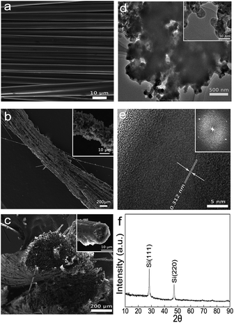
The morphology of as-synthesized Si/PPy/CFs products was examined by Scanning Electron Microscopy (SEM). A single CF was about 8 μm in diameter (Fig. 2a). The CF exhibited good electric conduction (ca. 8 Ω cm−1) and mechanical property. The illustration of Si/PPy/CFs (Fig. S1†) has demonstrated its twisted structure and good flexibility. Low-magnification SEM images (Fig. 2b) have clearly indicated the well-established textural structure of the as-grown Si/PPy on the CFs, some of which were tightened by the hybrid material as an internal crosslinking network. A higher magnification SEM image, as shown in the inset of Fig. 2b, indicates that the diameter of a single CF was 11–14 μm, a little wider than the bare CF (ca. 8 μm). Compared to a single bare CF with a smooth surface, the hybrid electrode appeared as a porous rough surface. Thermogravimetric analysis of pure CFs and Si/PPy/CF electrode in Fig. S2† shows that the Si weight percentage was 54.5% after in situ polymerization, indicating that plenty of SiNPs were adhered to CFs by the in situ polymerization method. The cross-sectional image of Si/PPy/CFs (Fig. 2c) shows a twisted structure identical to the one in Fig. S1.† The inset of Fig. 2c displays rolling-hill-like porous structure formed by stacked Si/PPy, corresponding to the structure in Fig. 2b. The elemental mapping in Fig. S3† presents the elemental distribution of anode, oxygen (green), carbon (red) and silicon (blue), thereby revealing the uniform SiNPs distribution on the surface of CFs skeleton.
To visualize the detailed microstructures of the as-grown Si/PPy/CFs structure, transmission electron microscopy (TEM) and high-resolution TEM (HRTEM) characterizations were carried out. The low-magnification TEM image of Si/PPy (Fig. 2d) indicates that the interconnected porous structure of Si/PPy was stable and even ultrasonication could not break it. The inset of Fig. 2d shows that the polymeric coating on the outer surface of the SiNPs was uniform and each SiNPs connected by a thin PPy layer and SiNPs were about 50 nm. The EDAX spectra (Fig. S4†) further show the O, C and Si elements in Si/PPy. The HRTEM image in Fig. 2e has shown a clear lattice spacing of 0.314 nm corresponding to (111) plane of Si, and a 10 nm thick wrapping layer of PPy on crystallized SiNPs in Si/PPy nanocomposites. Fig. 2f shows the X-ray diffraction pattern of Si/PPy/CFs electrode with the peaks30 of (111) at 27.91° and (220) at 48.01°. The diffraction peaks verify the cubic phase of Si (JCPDS: 77-2111). However, the carbon peak was not clear thereby revealing that carbon fiber was not in the crystallized form.
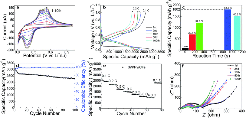
To demonstrate the electrochemical performance of as-synthesized 3D hierarchical Si/PPy/CFs electrode, products after in situ polymerization reaction for 900 s were chosen as the binder-free anode for the proposed homemade half cells. Fig. 3a shows the cyclic voltammogram (CV) curve at a scan rate of 0.2 mV s−1 for the initial 10 cycles at room temperature, whose voltage window is 0.01–1.0 V. In the first few cycles, current peaks in the CV measurement display the activation process in the SiNPs. It may benefit from the large surface area in accordance with the tunnel of mesopores for the interconnected structure.31 During the lithiation process, Si–Li alloying reaction began at 0.33 V and showed a peak in the CV plots; amorphous Si was transferred to LixSi, as observed from the peak at 0.17 V. During the delithiation process, two peaks at 0.42 V and 0.54 V correspond to the phase transformation from α-LixSi to α-Si.19,31 Fig. 3b shows the charge/discharge profiles of half-cell within the range of 0.01–1.0 V vs. Li/Li+. The specific capacity contributed from PPy and carbon fiber was calculated as 308 mA h g−1, as shown in Fig. S5.† Using the equation shown in the ESI,† the average discharge capacity was calculated as 3050 mA h g−1 at 0.1C (1C = 4200 mA h g−1). Compared to 2595 mA h g−1 in the charge curve, a coulombic efficiency of 84.9% for the 1st cycle was deduced. The next 2nd, 10th, 50th and 100th test were operated at 0.2C and showed almost same capacity retention as that of the cycling at 0.1C. This result can be attributed to the 3D high-porosity interconnected structure of PPy and SiNPs, and the FEC serving as an additive to the electrolyte, which enhanced the stability of the SEI at the surface of SiNPs.19,31 Fig. 3c has given a comparison between specific capacity against the reaction time for anode with various silicon percentages. From 103 mA h g−1 of the bare CFs, the specific capacity increased to 702 mA h g−1 (150 s) and 1207 mA h g−1 (300 s) with Si mass loading time. Then, it reached the highest 1802 mA h g−1 (900 s) at Si ratio of 54.5% in the whole electrode and dropped to 1503 mA h g−1 (1100 s, 60.2%). As shown in Fig. S5,† the connection established by the in situ polymerization reaction from PPy acted as glue bonding SiNP to SiNP and CFs (Fig. S5b†), then the composites built up a 3D interconnected porous framework (Fig. S5c†). As the deposition time went on, the PPy layer became thicker and thicker and finally blocked the mesopore structure (Fig. S5d†), leading to the fading capacity.32 The cycling performance was examined by galvanostatic charge/discharge experiments in which the first discharge capacity for the Si/PPy/CFs electrode was about 3050 mA h g−1. The wire-shaped anode showed a capacity retention over 74.9% and a coulombic efficiency over 97% for 2nd to 100th cycles. The good performance of wire-shaped anode may be attributed to the stabilized SiNPs well restrained into the interconnected framework composed of PPy cross-linked structure and the highly conductive CFs. The rate capability of composite electrode was exhibited in Fig. 3e, where the capacity retention of ternary electrode was 35% (ca. 936 mA h g−1 at 4C) when the current density increased from 0.1C to 4C. Furthermore, the reversible capacity of the composite anode almost recovered to the initial value after more than 80 cycles at a high current density. In order to understand the reason for the improved cycling capability of Si/PPy/CFs electrode in FEC-containing electrolyte, electrochemical impedance spectroscopy (EIS) measurements were performed after 1st, 2nd, 10th, 50th and 100th cycle. The impedance spectra of the cycling Si/PPy/CFs ternary electrode are exhibited in Fig. 3f. The typical Nyquist plots were made up with one depressed semicircle at high-to-middle frequency range and a straight line at low frequency range. However, in the present case, at high frequencies, the spectrum was related to the conductivity of the connections among contact resistance between copper wire and electrode; in the middle frequency range, Nyquist plots showed a small semicircle due to the formation of the SEI layer and the transfer resistance from the interface of the electrode. At low frequencies, diffusion process dominated in the Si/PPy/CFs.33 A remarkable decrease in the resistance appearing from 1st to 2nd plot could be ascribed to the conductivity improvement in Si/PPy/CFs electrode during lithium intercalation.33–37 Then, the resistance gradually decreased during the formation of a stable SEI layer.38
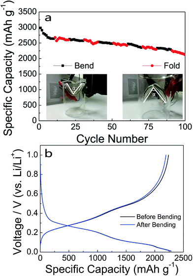
The cyclic performance of the flexible Si/PPy/CFs electrode was further studied. Fig. 4a reveals the specific capacities at bending and folding status with the help of a beaker. It was evident that the curve was continuous with no distinct drop during charging and discharging under a sharp bending or folding status of an angle. The capacity remained 2120 mA h g−1, 71.0% of the initial value after 100 cycles, indicating excellent performance after bending and folding. The specific capacity was preserved at 2197 mA h g−1 after bending for 100 cycles at 0.1C, comparable to the capacity of 2287 mA h g−1 without bending (Fig. 4b) (i.e., only a slight decrease of 3.9%).
Fig. 5a and b, c and d, e and f corresponded to the morphologies of Si/PPy/CFs electrode after 10, 50 and 100 cycles, respectively. The primary interconnected 3D porous structure was retained. Though the cross-linker PPy on CFs was extensively deformed upon repetitious charge/discharge process, electrical contact among Si/PPy/CFs was nearly unbroken under the protection of the deformable layer and the 3D framework of the electrode.16 Upon cycling, the active material expanded and shrank with time, and Si/PPy with less linkage finally lost its integrity and failed to contact CFs, while PPy appeared as cracks for balancing the huge internal stress.21 However, cracks exposed more surface of the active material while PPy on the surface of SiNPs was retained even after the cycling test, which helped to retain a tight contact between SiNPs and CFs under in situ polymerization synthesis process.39 The comparison between the proposed Si/PPy/CFs electrode and other devices (Fig. S8†) clearly showed a superior specific capacity, rate performance and an outstanding flexibility performance.
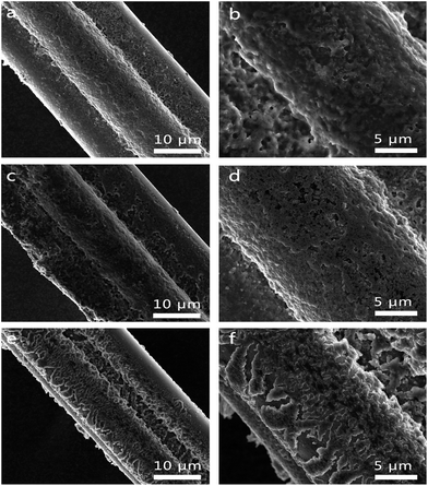 | ||
| Fig. 5 SEM images of Si/PPy/CFs wire-type electrode after 10 (a and b), 50 cycles (c and d) and 100 (e and f) cycles, showing the remaining interconnected structure. | ||
Overall, the cycle and rate performances of composite electrode and its flexibility were significantly enhanced due to its desirable features as follows. First, the interconnected 3D porous structure of PPy layer, as a frame, could be well maintained during the charge/discharge process, where nanoscale PPy not only helped promoting the electrical contact between electrode and electrolyte, but also played a role in protecting the shell, mechanically accommodating the vast volume changes to minimize the internal strain of the electrodes over cycles. During cycling, though PPy connection among the external SiNPs failed to some extent, most of crosslinked structure was well retained, thereby making the cycling retention and rate capability of Si/PPy/CFs anode superior. Second, in situ polymerized thin PPy coating on the outer surface of SiNPs assisted in enabling a deformable and stable SEI on SiNPs surface. Finally, introduction of CFs substrate into Si/PPy further provided support to enhance the flexibility and conductivity of the external 3D interconnected framework.
4. Conclusions
In conclusion, we proposed a novel interconnected 3D Si/PPy/CFs anode as a high performance wire-shaped LIB anode at large-scale and low-cost by in situ polymerization method. The electrode reveals a good retention, high rate performance upon cycling and an excellent performance during flexibility tests. The excellent electrochemical performance results of Si/PPy/CFs electrode with polyporous structure effectively survived the volume expansion of SiNPs during charge and discharge processes. The design for the large-scale synthesis of wire-shaped electrode shows promising applications.Acknowledgements
This study was supported by the National Natural Science Foundation of China (11374110, 11674113 and 51371085). Y. H. G. would like to thank Prof. Zhong Lin Wang for the support of experimental facilities in WNLO of HUST.Notes and references
- K. Jost, C. R. Perez, J. K. McDonough, V. Presser, M. Heon, G. Dion and Y. Gogotsi, Energy Environ. Sci., 2011, 4, 5060 CAS.
- X. Wang, X. Lu, B. Liu, D. Chen, Y. Tong and G. Shen, Adv. Mater., 2014, 26, 4763–4782 CrossRef CAS PubMed.
- G. Zhou, F. Li and H.-M. Cheng, Energy Environ. Sci., 2014, 7, 1307–1338 CAS.
- Y. H. Kwon, S. W. Woo, H. R. Jung, H. K. Yu, K. Kim, B. H. Oh, S. Ahn, S. Y. Lee, S. W. Song, J. Cho, H. C. Shin and J. Y. Kim, Adv. Mater., 2012, 24, 5192–5197 CrossRef CAS PubMed.
- H. Lin, W. Weng, J. Ren, L. Qiu, Z. Zhang, P. Chen, X. Chen, J. Deng, Y. Wang and H. Peng, Adv. Mater., 2014, 26, 1217–1222 CrossRef CAS PubMed.
- J. Ren, Y. Zhang, W. Bai, X. Chen, Z. Zhang, X. Fang, W. Weng, Y. Wang and H. Peng, Angew. Chem., Int. Ed., 2014, 53, 7864–7869 CrossRef CAS PubMed.
- J. Ren, L. Li, C. Chen, X. Chen, Z. Cai, L. Qiu, Y. Wang, X. Zhu and H. Peng, Adv. Mater., 2013, 25, 1155–1159 CrossRef CAS PubMed.
- N. Liu, Z. Lu, J. Zhao, M. T. McDowell, H.-W. Lee, W. Zhao and Y. Cui, Nat. Nanotechnol., 2014, 9, 1–8 CrossRef PubMed.
- B. a. Boukamp, T. Journal, M. C. Weeks, E. Voss, S. Yoshizawa, S. Okada, R. T. Mathieson, P. Press, E. L. Jones, G. Papazov, D. Pavlov, T. M. Company, E. J. Ritchie and C. Manufacturing, J. Electrochem. Soc., 1981, 128, 725 CrossRef CAS.
- Y. M. Chiang, Science, 2010, 330, 1485–1486 CrossRef CAS PubMed.
- D. Aurbach, J. Power Sources, 2000, 89, 206–218 CrossRef CAS.
- M. H. Park, M. G. Kim, J. Joo, K. Kim, J. Kim, S. Ahn, Y. Cui and J. Cho, Nano Lett., 2009, 9, 3844–3847 CrossRef CAS PubMed.
- C. K. Chan, H. Peng, G. Liu, K. McIlwrath, X. F. Zhang, R. A. Huggins and Y. Cui, Nat. Nanotechnol., 2008, 3, 31–35 CrossRef CAS PubMed.
- M. Ge, J. Rong, X. Fang and C. Zhou, Nano Lett., 2012, 12, 2318–2323 CrossRef CAS PubMed.
- H. Wu, G. Yu, L. Pan, N. Liu, M. T. McDowell, Z. Bao and Y. Cui, Nat. Commun., 2013, 4, 1943 Search PubMed.
- M. Kummer, J. P. Badillo, A. Schmitz, H. G. Bremes, M. Winter, C. Schulz and H. Wiggers, J. Electrochem. Soc., 2014, 161, A40–A45 CrossRef CAS.
- Y. Yao, N. Liu, M. T. McDowell, M. Pasta and Y. Cui, Energy Environ. Sci., 2012, 5, 7927 CAS.
- D. Shao, H. Zhong and L. Zhang, ChemElectroChem, 2014, 1, 1679–1687 CrossRef CAS.
- B. Liu, P. Soares, C. Checkles, Y. Zhao and G. Yu, Nano Lett., 2013, 13, 3414–3419 CrossRef CAS PubMed.
- S. Y. Chew, Z. P. Guo, J. Z. Wang, J. Chen, P. Munroe, S. H. Ng, L. Zhao and H. K. Liu, Electrochem. Commun., 2007, 9, 941–946 CrossRef CAS.
- Z. Du, S. Zhang, Y. Liu, J. Zhao, R. Lin and T. Jiang, J. Mater. Chem., 2012, 22, 11636–11641 RSC.
- H. Wolf, Z. Pajkic, T. Gerdes and M. WillertPorada, J. Power Sources, 2009, 190, 157–161 CrossRef CAS.
- Z. Du, S. Zhang, Y. Liu, J. Zhao, R. Lin and T. Jiang, Nano Lett., 2012, 12, 802–807 CrossRef PubMed.
- Y. Xu, Y. Zhu, F. Han, C. Luo and C. Wang, Adv. Energy Mater., 2015, 5, 1400753 CrossRef.
- J. Wu, X. Qin, C. Miao, B. Li and F. Kang, Carbon, 2016, 98, 582–591 CrossRef CAS.
- E. Frackowiak and F. Béguin, Carbon, 2002, 40, 1775–1787 CrossRef CAS.
- B. J. Landi, M. J. Ganter, C. D. Cress, R. a. DiLeo and R. P. Raffaelle, Energy Environ. Sci., 2009, 2, 638 CAS.
- S. L. Candelaria, Y. Shao, W. Zhou, X. Li, J. Xiao, J. G. Zhang, Y. Wang, J. Liu, J. Li and G. Cao, Nano Energy, 2012, 1, 195–220 CrossRef CAS.
- Y. P. Wu, E. Rahm and R. Holze, J. Power Sources, 2003, 114, 228–236 CrossRef CAS.
- J. K. Lee, K. B. Smith, C. M. Hayner and H. H. Kung, Chem. Commun., 2010, 46, 2025–2027 RSC.
- L. Wang, B. Gao, C. Peng, X. Peng, J. Fu, P. K. Chu and K. Huo, Nanoscale, 2015, 7, 13840–13847 RSC.
- G. Liu, W. S. Hung, J. Shen, Q. Li, Y. H. Huang, W. Jin, K. R. Lee and J. Y. Lai, J. Mater. Chem. A, 2015, 3, 4510–4521 CAS.
- Y. S. Hu, R. Demir-Cakan, M. M. Titirici, J. O. Moller, R. Schlogl, M. Antonietti and J. Maier, Angew. Chem., Int. Ed., 2008, 47, 1645–1649 CrossRef CAS PubMed.
- E. Pollak, G. Salitra, V. Baranchugov and D. Aurbach, J. Phys. Chem. C, 2007, 111, 11437–11444 CAS.
- M. V. Reddy, T. Yu, C. H. Sow, Z. X. Shen, C. T. Lim, G. V. Subba Rao and B. V. R. Chowdari, Adv. Funct. Mater., 2007, 17, 2792–2799 CrossRef CAS.
- M. V. Reddy, G. V. Subba Rao and B. V. R. Chowdari, J. Mater. Chem., 2011, 21, 10003 RSC.
- R. Ruffo, S. S. Hong, C. K. Chan, R. A. Huggins and Y. Cui, J. Phys. Chem. C, 2009, 113, 11390–11398 CAS.
- W. Weng, Q. Wu, Q. Sun, X. Fang, G. Guan, J. Ren, Y. Zhang and H. Peng, J. Mater. Chem. A, 2015, 3, 10942–10948 CAS.
- H. L. Anodes, ACS Nano, 2010, 4, 2233–2241 CrossRef PubMed.
Footnote |
| † Electronic supplementary information (ESI) available. See DOI: 10.1039/c7ra02051a |
| This journal is © The Royal Society of Chemistry 2017 |

