 Open Access Article
Theoretical study of the substitutional solute effect on the interstitial carbon in nickel-based alloy†
Xun Zhangab,
Cui-Lan Ren *ac,
Han Hana,
Xiang-Xi Yea,
Eugenia Kuod,
Cheng-Bin Wangac,
Wei Zhangac,
Li Jianga,
Gregory Lumpkind,
Ping Huaia and
Zhi-Yuan Zhu*ac
aShanghai Institute of Applied Physics, Chinese Academy of Sciences, Shanghai 201800, China. E-mail: rencuilan@sinap.ac.cn; zhuzhiyuan@sinap.ac.cn
bUniversity of Chinese Academy of Sciences, Beijing 100049, China
cKey Laboratory of Interfacial Physics and Technology, Chinese Academy of Sciences, Shanghai 2018004, China
dAustralian Nuclear Science and Technology Organization, Lucas Heights, New South Wales 2234, Australia
First published on 10th April 2017
Abstract
The carbon binding in nickel-based alloy with 3d, 4d and 5d transition metal solutes is investigated by using first-principles methods. The first nearest neighbor carbon exhibits repulsive behaviors with most metals except Cr element, which are analyzed from both mechanical and chemical aspects. It shows that the size factor from metal solute is one of the main reasons affecting 1NN carbon–metal binding. Further electronic structures analysis shows that the hybridization of C 2pz–M 3dz2 states plays an important role in C–M bonding. The introduced vacancy enhances carbon bonding to most metal solutes through local strain change and charge redistribution. Among all the metal solutes, Cr shows its affinity to carbon which coincides with the previous experimental observation that chromium carbides are commonly precipitated in nickel-based alloys. The present study helps to understand the carbon–metal solute interaction in nickel-based alloys.
1. Introduction
Nickel-based superalloys, due to their good high-temperature creep and fatigue strength, excellent corrosion resistance properties, are widely used as the structural materials in the energy industries. Carbon (C) is one of the most common foreign interstitial atoms (FIAs) in nickel-based alloys. With a low solubility in metal, carbon can be easily segregated, and react with metal solutes, then forming different kinds of carbides.1It is reported that composition segregation and metal carbides precipitation occurred in nickel-based alloys after heat treatment,2 irradiation,3 and corrosion.4,5 It is also reported that carbides, by controlling their morphology and distribution, can influence the properties of nickel-based alloys. The carbides are commonly utilized to improve the strength, hardness, and radiation resistance properties of nickel-based alloys. It is evidenced that the MC and M23C6 type carbides can improve the creep performance of alloys by inhibiting grain boundary migration during the deformation.6–8 The fine and dispersive M6C could improve the strength property through pining down the dislocation movement.8,9 Moreover, earlier researches in Oak Ridge National Laboratory (ORNL) showed that the MC type carbides can improve the radiation resistance property of alloys by the addition of limited concentration of Ti, Ha, Zr and Nb. This promotes the formation of finely dispersed MC type carbides, and then introduces numerous interfaces in the alloy matrix, which help to trap the helium rather than allow it to diffuse towards the grain boundaries.10,11 On the other hand, if carbides present as continuous films at the grain boundaries, it may have a detrimental effect on the ductility and toughness of the alloys.12
The 3d, 4d and 5d transition metal elements, as foreign substitutional atoms (FSAs), also play an important role in nickel-based alloy. For example, the elements Mo, W, Re, Cr, etc. are involved in the solid-solute strengthening; Cr can improve the oxidation resistance; Ti, Nb, Ta, Cr etc. can control the nucleation of γ′ precipitates. These elements trap or repel carbon due to their atom size and their different affinity to carbon (chemical effects). On the other hand, point defects such as vacancies could be easily introduced during nucleation, radiation and corrosion processes, and defects in alloy always serve as the trapping site for carbon. The metal solute as well as defects and their interactions can greatly affect the carbon solubility,13–16 diffusion,15,16 carbon segregation14 and carbide precipitations properties14,17 in nickel. However, it is extremely difficult to directly observe the behavior of carbon and the corresponding microcosmic mechanisms since all of the FIAs–FSAs interactions are atomic-scale problems.
Simulation technique such as first-principle calculation is the most appropriate method to precisely evaluate the atomic interactions and understand the basic mechanism involved. Theoretical studies have been carried out to investigate the behaviors of carbon FIAs–metal FSAs (C–M) interactions in alloys, especially in iron-based alloys. Liu et al.18 studied the C–M interactions in α-Fe, concluding that the C–M interactions are mostly possessed by the strain relief for 4d, 5d elements, while the effects from magnetic coupling and electronic structure may override that from the strain relief for some 3d elements. Simonovic et al.19 studied the Si effect on carbon diffusion in bcc Fe and found that Si prevented the diffusion of carbon and diminished the thermodynamic driving force for carbide formation in Fe. Zhang et al.20 studied the carbon diffusion behaviors in the presence of different solute elements in bcc Fe, finding that Mn has the best effect on trapping carbon and the formation of Ta carbide is energetically preferred by trapping carbon around Ta atom. Moreover, for the FIAs/FSAs behaviors in Ni-based alloys, Siegel et al.21 studied the solubility, diffusion and clustering properties of carbon in fcc Ni. It is reported that carbon prefers to occupy the octahedral (Oct) interstitial site more than tetrahedral (Tet) site, and the preferable diffusion path of carbon in nickel is Oct → Tec → Oct. Connétable et al.22 investigated the thermodynamic solubility energies of the metal, insertion energies of FIAs and presented a complete database of the solubility for most solid solution in nickel. Janotti et al.23 studied the solute diffusion activation energies for different transition metals. Schuwalow et al.24 studied the interaction of refractory metal elements such as Re, Ta, W and Mo solutes with vacancies in Ni. Yamaguchi et al.,25 Vsianska et al.26 and Liu et al.27 calculated the segregation properties for numerous elements in nickel grain boundaries. These studies help to clarify the interaction behaviors for different FIAs, FSAs in alloys, however, the in-depth mechanism, especially the interaction mechanism among C FIAs, metal FSAs and vacancy has not been fully understood.
In this work, the first principles calculations are performed to study the carbon–metal solute interaction effect in nickel-based alloys. The binding energies of carbon at different sites in alloy with different transition metals are calculated to understand the corresponding mechanisms. Detailed spin-resolved projected density of states (PDOS) and charge density difference (CDD) are analyzed to elucidate the bonding nature between carbon and metal solutes. These results will be help in further understanding of the carbon behaviors such as carbon solubility, carbon–metal solute interaction as well as the carbide precipitation in nickel-based alloys.
2. Theoretical details
The first-principles calculations are performed by using the density-functional theory (DFT)28 implemented in the Vienna ab initio simulation package (VASP),29–31 using the generalized gradient approximation (GGA) with the parameterization of PW91.32 The electron–ion interaction are described by using the projector-augmented wave (PAW) potentials.33 During the calculation, the recommended standard potentials are used for all the elements except for Nb and Y elements (using Nb_sv and Y_sv). The energy cutoff for the plane wave expansion is set to 400 eV to ensure good convergence. Spin polarized calculations are performed for nickel in consideration of that nickel is magnetic. The geometry optimization is performed using conjugate gradient scheme with a force convergence criterion 0.01 eV Å−1.The face-centered cubic (fcc) nickel lattice model contains 108 atoms, corresponding to 27(3 × 3 × 3) fcc unit cells. The Brillouin zone is sampled by the Monkhorst–Pack scheme with a 3 × 3 × 3 k-point mesh. The second-order Methfessel–Paxton method with smearing width of 0.2 is used for relaxation. The difference of energy per nickel atom are less than 1 meV with the smearing width of 0.1 and 0.15. With current parameter, the basic parameters of bulk nickel are calculated to check the reliability of the model. The lattice constant, binding energy, average magnetic moment and vacancy formation energy are calculated to be 3.52 Å, 4.83 eV, 0.60 μB per atom and 1.36 eV, respectively, which are consistent with the previous experimental13,34–39 and DFT21,40–42 results. The vacancy formation energy in Ni with different k-point mesh are also calculated to do the convergence test. It shows that the 3 × 3 × 3 k-point mesh is sufficient. The vacancy formation energy is calculated to be 1.36 eV and the differences with that of 5 × 5 × 5 and 7 × 7 × 7 k-point mesh are less than 0.01 eV.
To evaluate the C–M (M: 3d, 4d, 5d metal solute) interaction behaviors, a model with one nickel atom substituted by M atom is constructed. The carbon atom is inserted to the first to fourth nearest neighbor (1NN to 4NN) Oct sites relative to the metal solute to model the C–M interactions, as showed in Fig. 1(a). For an in-depth comparison with that of C–M interaction, the carbon–metal FSAs–vacancy (C–M–V) models are also constructed on the base of C–M model by moving one nickel atom in 1NN site of the metal solute, as shown in Fig. 1(b).
3. Results and discussion
3.1 Carbon–metal interaction in nickel
The formation energy of carbon atoms in nickel is initially calculated to investigate their stability in nickel. It is defined by Ef = (E108Ni+nC − E108Ni − nEc)/n, where E108Ni+nC refers to the energy of nickel with 108 nickel atoms and n carbon atoms, while E108Ni and EC are the energy of the nickel matrix and the formation energy of carbon in graphite, respectively. One to three carbon atoms doping are considered in the calculation. It is found that the carbon atom is more stable in Oct site with a formation energy of 0.74 eV comparing with that in Tet site (see Table S1†), which is consistent with previous reports.21 The formation energy of carbon increases with the carbon concentration, indicating that the isolated interstitial carbon is energetically favorable in nickel (see Table S2†). It is coincident with previous study that C–C interaction in the nearest neighbor site is slightly repulsive in nickel.21 As is also known, the carbon contents in general nickel-based alloys are very low. Therefore, only one carbon atom is considered in most of the following calculations due to the limitation of the model.It is known that metal solute would inevitably affect the carbon binding in nickel. When the metal solutes are introduced to model the nickel-based alloy, as shown in Fig. 1(a), the binding energy of carbon in nickel-based alloy with different metal solutes can be defined as:
| ECb = E107Ni+M+C − E107Ni+M − E108Ni+C + E108Ni | (1) |
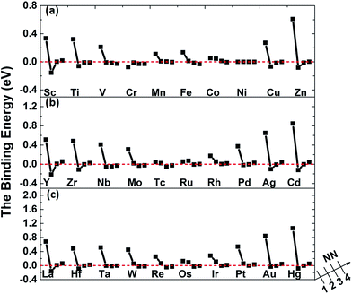
The binding energies of carbon in nickel alloy with 3d, 4d, 5d transition metal solutes are shown in Fig. 2. For each metal solute, the binding energy of carbon located at its 1NN to 4NN neighbor Oct sites are calculated and compared with that in Oct site of pure nickel (0 eV, see the dashed red line in Fig. 2). It shows that the binding energies of carbon exhibit the similar tendency for most of elements in 3d, 4d, 5d, except for the Cr element in 3d which shows a more attractive interaction with carbon for all of the four atomic configurations. For alloys with most of the metal solutes, carbon is unfavorable at 1NN Oct site with much higher binding energy comparing with the 2NN–4NN sites. The binding energy of carbon at 1NN site decreases and then increases with the metal elements from left to right. Moreover, the binding energy decreases sharply with the relative C–M distance increasing to 2NN comparing with 1NN site, indicating that the 2NN site is energetically preferable for carbon. Furthermore, the calculated binding energies for carbon at 3NN–4NN Oct sites are similar to each other, and the values are quite similar to that in pure nickel, implying that the local metal solute effects on carbon are less than the 3NN distance. The small fluctuations for carbon binding energy around 0 eV at 3NN–4NN sites can be explained by the elastic effects.18
The binding between carbon and metal solutes in nickel can depend on both mechanical and chemical effects. The metal solutes, due to the mismatch in atomic size with the host nickel matrix atoms, would inevitably lead to local strain field and lattice distortion. Therefore, the size factor inducing mechanical effect would not only affect carbon but also the adjacent nickel atoms. Besides, the existence of metal solutes can also induce the charge redistribution between carbon, solute and nickel, which would also affect their interactions.
As mentioned above, the binding energies of carbon at 2NN site are much lower, however, the 2NN C–M distance is about 3.94 Å, which is much longer than the C–M bond length in all of the typical carbides. It is more important to study the interaction between carbon and metal solute on the 1NN shell in nickel-based alloys. Hence, the following analyses focus on 1NN C–M interaction.
3.2 Mechanical effect (size factor) of metal solute
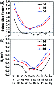
The size factor of metal solute in the nickel matrix is calculated and analyzed to get an improved understanding with mechanical effect. Herein, the size factor is defined as ΩMsf = (ΩcellM − ΩcellNi)/ΩNi, where ΩcellM, ΩcellNi and ΩNi are the volume of supercell with the solute M, the defect-free supercell and the volume of one nickel atom,43 respectively. The predicted size factors for 3d, 4d, 5d metal elements as single solute in nickel matrix are calculated and shown in Fig. 3(a). It should be acknowledged that the local strain effects on the binding energy of carbon decrease sharply from 1NN site to 4NN site with the increases of distance from stress field. Hence, only the binding energy of carbon at 1NN site of the metal solutes are plotted and shown in Fig. 3(b) for a better comparison. It shows that the binding energies have the similar tendency with the solute size factor for the most of 3d, 4d, 5d metals. The mismatch between solute and host atom can be inferred to be the physical origin of mechanical component. The binding ability of carbon to the alloy can be affected by the strain field from the doped metal solutes.The carbon binding energy as a function of metal solute size factor in M–Ni systems is also plot in another form and shown in Fig. S1.† However, it shows that the size factor and binding energies are not completely linear, meaning there is other factor affecting carbon binding. As shown in Fig. 3(a), the insertion of V, Cr, Mn, Fe, Co and Cu into Ni lattice produces a weak local stress, due to their similar atom size. However, the carbon binding energy in Cr doped nickel system drops a lot compared with that in its adjacent element such as V, Mn and Fe doped nickel systems. Hence, the C–M interaction in nickel may depend not only on the local strain from size factor but also the chemical effects between carbon and metal solutes.
3.3 Chemical effects (electronic structural analyses)
To further understand the chemical binding mechanism between carbon–metal solute, the electronic structures analyses including the PDOS and CDD of specified systems are calculated and analyzed.The PDOSs for pure Ni and carbon doped Ni systems are plotted in Fig. S2.† For pure nickel system, the PDOS of nickel at the Fermi level is dominated by the 3d states of Ni atoms, showing a typical metallic bonding among them. For carbon-doped nickel system, the hybridized C-2p and Ni-3d states appears in a range of −7.5 to −6 eV, which indicates a strong p–d covalent bonding between the doped carbon and the nearest nickel atom. Since the overall PDOS shapes in energy range as well as the position of the DOS peaks are similar for the pure Ni and C-doped Ni in Fig. S2(c–f),† it is reasonable to conclude that the C 2pz–Ni 3dz2 hybridization (see Fig. S2(e)†) plays a key role in the C–Ni interaction. Therefore, we focus on the hybridization between these two orbitals in the next discussions.
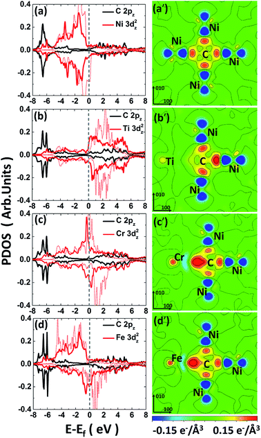
For the C-doped M–Ni system (noted as C–M–Ni for convenient), the C–Cr–Ni, C–Ti–Ni and C–Fe–Ni in 1NN configuration with C occupies at Oct site are compared with that of C–Ni system. The left panel of Fig. 4 displays the PDOS of these four systems. For clarity, only the C 2pz and M 3dz2 orbital components involved in the interactions are plotted. Similar to the C–Ni system, the hybridized C-2p and M-3d states appear in a range of −7.5 to −5 eV for all the C–M–Ni (M: Ti, Cr and Fe) systems. For the non-doped Ti–Ni system, most of the Ti 3dz2 states are empty states, indicating a strong ionic character of Ti in Ni metal. Therefore, the covalent bonding between C–Ti should be relatively weak after C doped by comparing with the C–Cr–Ni and C–Fe–Ni systems. The resonance region for C–Cr as well as that of C–Fe is −7.5 to −3 eV below the Fermi level, and it shows that there is covalent components in C–Cr and C–Fe bond. By comparing Fig. 4(c) with 4(a), the hybridized C 2pz–Cr 3dz2 states is deeper and stronger than that of C–Ni, indicating the stronger C–Cr interaction.
The CDD is defined as follows, Δρ = ρCMNi − ρMNi − ρC, where ρCMNi refers to the total charge density of C–M–Ni system, ρMNi is the charge density of C–M–Ni system with the carbon atom removed and ρC is the charge density of the removed carbon atom. The CDD of the four considered systems, C–Ni, C–Ti–Ni, C–Cr–Ni and C–Fe–Ni, are shown in Fig. 4(a′–d′), respectively. It is obtained that the hybridized C 2pz–Cr 3dz2 states plays a dominant role in C–M bonding. It also can been seen that the spatial CDD around the metal atom are in the shape of 3dz2 orbital, which is coincident with the above PDOS analyses. It is clear that the charge transfer between C and Ti in C–Ti–Ni system is negligible due to the ionic character of Ti in Ni discussed above. For the C–Cr–Ni system, the negatively charged area between C and Cr indicates a stronger covalent bonding of C–Cr than C–Ni. It also can be seen that there are more electrons accumulating between C and Cr than those between C and Fe, revealing that C–Cr bond is stronger than C–Fe bond.
From the analyses of PDOS and CDD, it indicates that the C–Ti bond shows ionic character which weakens the carbon binding ability, while the covalent component of C–Cr bond shows its affinity to carbon, moreover, the CDD of C–Fe shows a little weaker interaction between C–Fe than C–Cr which is in charge of the weak repulsion 1NN C–Fe behavior.
Combining the results of both mechanical effect and chemical effect analyses, two typical systems C–Ti–Ni and C–Cr–Ni are also chosen to further explore the effect of carbon content on carbon binding behaviors in Ni-based alloy. It shows that the carbon binding energy increases when more carbon atoms added in the 1NN Oct sites relative to the Ti/Cr atom, as shown in Table S2.† In C–Ti–Ni system, the C–Ti interaction is due to the size factor in larger extent. Larger local lattice distortion would be caused by adding more carbon atoms. Therefore, the C–Ti binding becomes more repulsive. However, in Cr-doped Ni system, the C–Cr interaction is dominated by their covalent bonding. Hence, the local elastic distortion caused by adding more carbon atoms only slightly weakens the C–Cr binding, as the binding energy shown in Table S2.†
3.4 C–M–V interaction in nickel
Similar with metal solute, defects in alloy can also lead to local strain. It also known that defect can serves as sink for carbon. As carbon in pure nickel for example, the formation energy is calculated with the definition, Ef = E107Ni+C − E107Ni − Ec, where E107Ni+C, E107Ni and EC are the energies of the nickel with the interstitial carbon atom and a vacancy, the nickel with a vacancy, and the formation energy of carbon in graphite, respectively. The formation energy of carbon locates at 1NN site to vacancy is calculated to be 0.65 eV, which is 0.09 eV lower than that in pure nickel, indicating that vacancy enhance the binding between carbon and nickel (see Table S1†). Moreover, the local vacancy effect on carbon is also less than the 3NN distances since that the formation energy between vacancy and its 3NN carbon is close to 0.74 eV, which is similar with that in pure nickel.To further investigate the carbon–metal–vacancy interaction, a vacancy is introduced based on the carbon–metal interaction model, the binding energy of carbon with M–V pair in the alloy is define as
| ECb = E106Ni+M+C − E106Ni+M − E108Ni+C + E108Ni | (2) |
Fig. 5 shows the binding of carbon in nickel with M–V pair as carbon at 1NN to the 4NN site relative to metal solutes. By comparing with the data in Fig. 2, it is clear to find that the introduced vacancy enhances the 2NN and 3NN C–M binding with lower binding energy. Nevertheless, the situation is more complicated on the 1NN shell. For example, the binding energies of carbon in Sc–V–Ni at 1NN site is 0.69 eV that is 0.34 eV higher than that in Sc–Ni, which means that carbon is repulsed after the vacancy introduced. For the metal solutes located in the middle range of the periodic table, such as the V, Cr, Mn, Fe, Co and Ni in 3d metal, the solutes behave more attractive to carbon after vacancy being introduced. As for the 3d metals in right part of periodic table, carbon shows repulsive behaviors in M–V–Ni (M: Cu and Zn) again comparing with that in M–Ni systems. The similar situation also exists in the systems with 4d or 5d metal solutes. Moreover, local effects from solute–vacancy pair reduce with the increasing distance away from the vacancy, which can be negligible when their distance is larger than 3NN shell, as shown in Fig. 5.
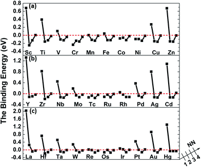 | ||
| Fig. 5 The binding energies of carbon in nickel alloy with 3d (a), 4d (b), 5d (c) metal solutes–vacancy pairs. | ||
It is noteworthy that the binding energies of carbon in Cr–V–Ni system distinctly reduce to below zero and the value of 1NN carbon is lowest among all solute, indicating that Cr–V pair exhibits the most attraction to carbon. By comparing the C–M and C–M–V interactions in nickel, Cr behaves attractive interaction with carbon for all of the four atomic configurations, and their attractive interactions enhance after the vacancy being introduced, indicating that Cr and Cr–V pair are both favorable to capture carbon. As reported by previous experiments,44,45 the typical chromium carbides such as Cr6C, Cr23C6 can be easily formed in high Cr-content nickel-based alloy especially at the grain boundaries, which also reveals the high attraction effect of Cr to carbon experimentally.
As mentioned above, the binding between C–M is weakened or enhanced after vacancy being introduced. For example, the binding energy of carbon in Ti–V–Ni increases slightly while it decreases in Cr–V–Ni system. The vacancy in lattice not only affects the local strain, but also results in the redistribution of the local charge density. Similar to the solute size factor mentioned above, the solute–vacancy size factor is defined as ΩM+vacsf = (ΩcellM+vac − ΩcellNi)/ΩNi, where ΩM+vacsf, ΩcellM+vac and ΩcellNi are the volume of supercell with the solute M and one vacancy, the defect-free supercell and the volume of a nickel atom,18 respectively. As shown in Fig. 6, the size factor of M–V–Ni system shows more linear trend comparing with that of M–Ni system (See Fig. S1†) and the binding energies of 1NN carbon in M–V–Ni systems are nearly linearly correlated with the size factors, indicating that the interactions between M–V and carbon are dominated by the size factors. Vacancy enhances the mechanical effects on carbon binding in nickel-based alloys, which is principally responsible for the changes of the binding energies on 1NN shell with vacancy.
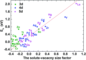 | ||
| Fig. 6 The C–M–V–Ni binding energy for carbon at 1NN as a function of the solute–vacancy size factor. | ||
The CDD maps for M–V–C–Ni systems are also calculated to further elaborate the different carbon behaviors before and after vacancy being introduced. It is shown that there are more electrons accumulating between carbon and the metal solute adjacent to vacancy, by comparing Fig. 7(a–b) with 4(b′–c′). In other words, the vacancy enhances the chemical interactions between carbon and metal solutes. The local strain effect on carbon weakens sharply for 2NN and 3NN sites, and the chemical effect plays a major role in carbon binding to supercells. Hence, the enhanced C–M interactions result in lower binding energies in M–V–C–Ni systems outside 1NN shell.
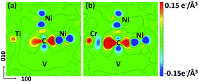 | ||
| Fig. 7 CDD maps of (a) CTiNi106 and (b) CCrNi106 with one vacancy being introduced at the 1NN site of Ni and C. The Ti, Cr, C and Ni atoms are all labeled. The vacancy is labeled as V. | ||
4. Conclusions
In a summary, the substitutional 3d, 4d and 5d transition metal solute effect on the interstitial carbon in nickel-based alloys are systematically investigated by using first-principles calculations with projector augmented plane wave method.(1) The carbon binding behaviors and their interaction with metal solutes are considered from both mechanical and chemical components. The 1NN carbon exhibits repulsive behaviors with most transition metals except Cr, which shows much attractive interaction with carbon. The size factor from metal solute affects the C–M binding since the similarity trend between the 1NN carbon binding energy and the corresponding metal size factors in nickel. Further detailed electronic structures analyses show that the hybridization of C 2pz–M 3dz2 states plays an important role in C–M bonding. Much stronger C p–M d bonding is one of the main reason for stronger C–Cr interactions.
(2) The introduced vacancy changes its local strain and causes local charge density redistribution. The interactions between M–V and 1NN carbon are dominated by the M–V pair size factors, which is mainly in charge of the variation of the binding energies on 1NN shell. The enhancement of 2NN, 3NN carbon atoms binding to nickel with M–V pair is due to its charge density redistribution.
(3) Cr and Cr–V pair show their affinity to carbon, which is coincide with the experimental phenomena that chromium carbides are easily formed in nickel-based alloys.
These results help to understand the basic carbon binding behaviors related to carbide precipitation in nickel based alloys.
Acknowledgements
This work was partially supported by the Program of International S&T Cooperation (Grant No. 2014DFG60230), the strategically Leading Program of the Chinese Academy of Sciences (Grant No. XDA02040100), the National Natural Science Foundation of China (Grant No. 11505266, 11605273), the Shanghai Municipal Science and Technology Commission (16ZR1443100). We also acknowledge the Supercomputer Center, CAS and TMSR supercomputer center for providing computing resources.References
- H. Matysiak, M. Zagorska, J. Andersson, A. Balkowiec, R. Cygan, M. Rasinski, M. Pisarek, M. Andrzejczuk, K. Kubiak and K. J. Kurzydlowski, Materials, 2013, 6, 5016–5037 CrossRef.
- G. D. Pigrova and A. I. Rybnikov, Phys. Met. Metallogr., 2013, 114, 593–595 CrossRef.
- H. McCoy Jr, An Evaluation of the Molten Salt Reactor Experiment Hastelloy N Surveillance Specimens: First Group, Oak Ridge National Lab, Tennessee, ORNL-TM-1997, 1967 Search PubMed.
- L. C. Olson, J. W. Ambrosek, K. Sridharan, M. H. Anderson and T. R. Allen, J. Fluorine Chem., 2009, 130, 67–73 CrossRef CAS.
- L. Olson, K. Sridharan, M. Anderson and T. Allen, Mater. High Temp., 2010, 27, 145–149 CrossRef CAS.
- Q. Chen, C. Jones and D. Knowles, Mater. Sci. Eng., A, 2004, 385, 402–418 CrossRef.
- L. He, Q. Zheng, X. Sun, H. Guan, Z. Hu, A. Tieu, C. Lu and H. Zhu, Mater. Sci. Eng., A, 2005, 397, 297–304 CrossRef.
- K. Zhao, Y. Ma and L. Lou, J. Alloys Compd., 2009, 475, 648–651 CrossRef CAS.
- L. Liu, T. Jin, N. Zhao, X. Sun, H. Guan and Z. Hu, Mater. Sci. Eng., A, 2003, 361, 191–197 CrossRef.
- M. Staff, The Development Status of Molten-Salt Breeder Reactors, Oak Ridge National Lab, Tennessee, ORNL-4812, 1972 Search PubMed.
- M. Rosenthal, P. Haubenreich, H. McCoy and L. McNeese, At. Energy Rev., 1971, 9, 601 CAS.
- C. T. Sims, N. S. Stoloff and W. C. Hagel, Superalloys II: High Temperature Materials for Aerospace and Industrial Power, John Wiley and Sons, New York, 1987, pp. 3–26 Search PubMed.
- H. Matter, J. Winter and W. Triftshäuser, Appl. Phys., 1979, 20, 135–140 CAS.
- A. Shulga, J. Alloys Compd., 2007, 436, 155–160 CrossRef CAS.
- J. Zhang, M. Safarzadeh and D. J. Young, Oxid. Met., 2008, 70, 15–24 CrossRef CAS.
- B. Bokhonov, A. Ukhina, D. Dudina, A. Anisimov, V. Mali and I. Batraev, RSC Adv., 2015, 5, 80228–80237 RSC.
- C. J. Marvel, P. R. Cantwell and M. P. Harmer, Scr. Mater., 2015, 96, 45–48 CrossRef CAS.
- P. Liu, W. Xing, X. Cheng, D. Li, Y. Li and X.-Q. Chen, Phys. Rev. B: Condens. Matter Mater. Phys., 2014, 90, 024103 CrossRef.
- D. Simonovic, C. K. Ande, A. I. Duff, F. Syahputra and M. H. F. Sluiter, Phys. Rev. B: Condens. Matter Mater. Phys., 2010, 81, 054116 CrossRef.
- C. Zhang, J. Fu, R. Li, P. Zhang, J. Zhao and C. Dong, J. Nucl. Mater., 2014, 455, 354–359 CrossRef CAS.
- D. J. Siegel and J. Hamilton, Phys. Rev. B: Condens. Matter Mater. Phys., 2003, 68, 094105 CrossRef.
- D. Connétable, É. Andrieu and D. Monceau, Comput. Mater. Sci., 2015, 101, 77–87 CrossRef.
- A. Janotti, M. Krčmar, C. Fu and R. Reed, Phys. Rev. Lett., 2004, 92, 085901 CrossRef CAS PubMed.
- S. Schuwalow, J. Rogal and R. Drautz, J. Phys.: Condens. Matter, 2014, 26, 485014 CrossRef PubMed.
- M. Yamaguchi, M. Shiga and H. Kaburaki, J. Phys.: Condens. Matter, 2004, 16, 3933 CrossRef CAS.
- M. Všianská and M. Šob, Prog. Mater. Sci., 2011, 56, 817–840 CrossRef.
- W. Liu, H. Han, C. Ren, H. Yin, Y. Zou, P. Huai and H. Xu, Comput. Mater. Sci., 2015, 96, 374–378 CrossRef CAS.
- P. Hohenberg and W. Kohn, Phys. Rev., 1964, 136, B864–B871 CrossRef.
- G. Kresse, J. Non-Cryst. Solids, 1995, 192, 222–229 CrossRef.
- G. Kresse and J. Furthmüller, Phys. Rev. B: Condens. Matter Mater. Phys., 1996, 54, 11169 CrossRef CAS.
- G. Kresse and D. Joubert, Phys. Rev. B: Condens. Matter Mater. Phys., 1999, 59, 1758 CrossRef CAS.
- J. P. Perdew and Y. Wang, Phys. Rev. B: Condens. Matter Mater. Phys., 1992, 45, 13244 CrossRef.
- P. E. Blöchl, O. Jepsen and O. K. Andersen, Phys. Rev. B: Condens. Matter Mater. Phys., 1994, 49, 16223–16233 CrossRef.
- W. Wycisk and M. Feller-Kniepmeier, Phys. Status Solidi A, 1976, 37, 183–191 CrossRef CAS.
- S. Nanao, K. Kuribayashi, S. Tanigawa and M. Doyama, J. Phys. F: Met. Phys., 1977, 7, 1403 CrossRef CAS.
- J. Campbell, C. Schulte and J. Jackman, J. Phys. F: Met. Phys., 1977, 7, 1985 CrossRef CAS.
- K. Lynn, C. Snead Jr and J. Hurst, J. Phys. F: Met. Phys., 1980, 10, 1753 CrossRef CAS.
- J. Wolff, M. Franz, J.-E. Kluin and D. Schmid, Acta Mater., 1997, 45, 4759–4764 CrossRef CAS.
- C. Kittel, Introduction to Solid State Physics, John Wiley and Sons, New York, 2005 Search PubMed.
- E. H. Megchiche, S. Pérusin, J.-C. Barthelat and C. Mijoule, Phys. Rev. B: Condens. Matter Mater. Phys., 2006, 74, 064111 CrossRef.
- P. K. Nandi, M. Valsakumar, S. Chandra, H. Sahu and C. Sundar, J. Phys.: Condens. Matter, 2010, 22, 345501 CrossRef PubMed.
- J. Jin Kim, S. Hun Shin, J. Ang Jung, K. Joon Choi and J. Hyun Kim, Appl. Phys. Lett., 2012, 100, 131904 CrossRef.
- P. Olsson, T. Klaver and C. Domain, Phys. Rev. B: Condens. Matter Mater. Phys., 2010, 81, 054102 CrossRef.
- H. Li, S. Xia, B. Zhou and W. Liu, Mater. Charact., 2012, 66, 68–74 CrossRef CAS.
- B. Tang, L. Jiang, R. Hu and Q. Li, Mater. Charact., 2013, 78, 144–150 CrossRef CAS.
Footnote |
| † Electronic supplementary information (ESI) available. See DOI: 10.1039/c7ra01823a |
| This journal is © The Royal Society of Chemistry 2017 |


