 Open Access Article
Creative Commons Attribution 3.0 Unported Licence
Synergistic effects of silica nanoparticles/polycarboxylate superplasticizer modified graphene oxide on mechanical behavior and hydration process of cement composites
Li Zhao a,
Xinli Guo*a,
Yuanyuan Liua,
Chuang Gea,
Liping Guob,
Xin Shuc and
Jiaping Liubc
aJiangsu Key Laboratory of Advanced Metallic Materials, School of Materials Science and Engineering, Southeast University, Nanjing 211189, China. E-mail: guo.xinli/seu.edu.cn
bJiangsu Key Laboratory of Civil Engineering Materials, School of Materials Science and Engineering, Southeast University, Nanjing 211189, China
cJiangsu Subote New Material Co., Ltd., Nanjing 211103, China
First published on 15th March 2017
Abstract
In this paper, the graphene oxide (GO) modified by polycarboxylate superplasticizer (PC) (PC@GO) was decorated by silica nanoparticles (SiO2 NPs) to form a hybrid structure of SiO2 NPs/PC@GO. The as-prepared SiO2 NPs/PC@GO hybrid was incorporated in cement matrix for further reinforcement. The results show that SiO2 NPs are uniformly distributed on the surface of GO nanosheets. The addition of SiO2 NPs/PC@GO hybrid (1.5% SiO2 and 0.02% GO by weight of cement) can increase the compressive strength by factors of 38.31%, 44.47% and 38.89% at 3, 7, 28 days, respectively, which are much higher than those of cement composites reinforced by a single-promoter (either PC@GO or SiO2 NPs). Moreover, our results demonstrate that SiO2 NPs/PC@GO hybrid can accelerate the cement hydration, improve the degree of pozzolanic reaction and refine the microstructure of hydration products. The excellent reinforcement is attributed to the synergistic effects of SiO2 NPs/PC@GO hybrid including better dispersion property, higher degree of pozzolanic reaction and cross-linking structure of [SiO2–GO–CSH]. This work provides a very effective way to reinforce cement composites by SiO2 NPs/PC@GO hybrid.
1. Introduction
Cement-based composites are the most important and widely used building materials at present. However, their inherent quasi-brittle behavior has limited their structural applications due to the associated crack propagation and poor tensile strength. Researchers have employed the use of cement composites with a wide variation of reinforcements, such as steel bars, steel fibers, glass fibers, polymer fibers and carbon fibers, etc. However, the traditional reinforcements are either in the macro-scale or micro-scale; they can enhance the crack-resistance in the macro/micro scale, but they fail to stop the initiation and propagation of nano-cracks.1–3 Therefore, this creates a need to use a material with nano-size dimension as the reinforcing agent for cement-based materials.Graphene has emerged as the star of carbon nano-material due to its exceptional mechanical, electrical and thermal properties.4 However, difficulties in dispersing graphene and high cost of production limit its widespread applications. As a graphene derivative, graphene oxide (GO) is the product of chemical oxidation and subsequent exfoliation of nature graphite flakes (inexpensive source). During oxidation, many oxygen-containing functional groups are introduced on GO surface, rendering GO nanosheets hydrophilic and easy to disperse in water.4 The high specific surface area, extraordinary intrinsic strength and good dispersion property make GO an attractive candidate for reinforcing cement composites. It is reported that the addition of GO can accelerate cement hydration, regulate the microstructure of hydration crystals and significantly improve the mechanical behavior of cement composites.2,3,5–8 However, it is difficult to disperse GO nanosheets in alkaline cement matrix due to the electrostatic interactions between the negatively charged GO layers and Ca2+, K+, Na+ OH− ions in cement pore solution. So either chemical modification or the use of surfactant is needed to achieve uniformly dispersed GO nanosheets in alkaline cement matrix. Concerns are raised regarding the inevitable side-effects of these modification agents or surfactants. For instance, they can retard cement hydration, entrap substantial air or improve the viscosity of cement paste.9–12 The positive effects of GO may be impaired due to the side-effects of modification agents or surfactants. Therefore, there is a trade-off between the positive effects of GO with high dosage and the negative influences of modification agents or surfactants.
SiO2 NPs with high specific surface area have been widely utilized to reinforce cement composites and have produced remarkable improvement in mechanical strength on account of nucleus effects and filling effects.13 Moreover, SiO2 NPs with pozzolanic activity can consume calcium hydroxide (CH) to form stable calcium silicate hydrate (C–S–H) gels. These advantages of SiO2 NPs provide the motivation to hybridize with GO nanosheets for further enhancement in mechanical properties of cement composites.
Although numerous studies have been conducted concerning the reinforcing effects of various nano-materials on cement composites, very limited researches have been carried out on the co-effects of 0D SiO2 NPs and 2D GO nanosheets on mechanical behavior and hydration process of cementitious materials. In this research, a hybrid structure of SiO2 NPs decorated PC@GO was prepared and incorporated in cement composites for further reinforcement. The hydration characteristics of cement pastes with the addition of nano-additives (SiO2 NPs and/or PC@GO) were also examined by means of isothermal calorimetry, thermal gravity analysis (TGA) and differential scanning calorimetry (DSC). Microstructure of hydration products was examined by means of scanning electron microscope (SEM) equipped with an energy-dispersive X-ray spectrometer (EDS). Based on these results, the mechanisms of synergistic effects of SiO2 NPs/PC@GO hybrid on cement hydration and pozzolanic reaction were proposed at last. This research may pave a novel way to prepare cement composites with significantly enhanced mechanical properties reinforced by SiO2 NPs/PC@GO hybrid.
2. Experimental
2.1. Materials
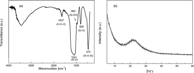
Portland cement conforming to the requirements of type P.I. 52.5R and standard sand were used in this research. The chemical composition of cement and the gradation of sand are listed in Tables 1 and 2, respectively. The chemicals used in this research were graphite (size ≤ 30 μm), concentrated sulfuric acid (H2SO4, 98%), potassium permanganate (KMnO4), sodium nitrate (NaNO3) and hydrogen peroxide (H2O2, 30%). Polycarboxylate superplasticizer (PC) with solid content of 40% was used as the modification agent of GO. Commercially available SiO2 NPs with a mean particle size of 15 nm provided by Aladdin were used in this study. The Fourier transform infrared (FT-IR) spectra and X-ray diffraction (XRD) pattern of SiO2 NPs are shown in Fig. 1(a) and (b), respectively. The characteristic peaks at 470.28 cm−1, 806.47 cm−1 and 1041.26 cm−1 demonstrate the existence of Si–O–Si and Si–O groups. A tiny peak at 960.34 cm−1 referring to the bending vibration of silanol groups (Si–OH) suggests that the SiO2 NPs used in this research take the form of hydrated silica. The broaden peak between 15° and 30° in Fig. 1(b) signifies the amorphous structure of SiO2 NPs.| Composition | Percentage (%) |
|---|---|
| CaO | 64.47 |
| SiO2 | 20.87 |
| Al2O3 | 4.87 |
| Fe2O3 | 3.59 |
| MgO | 2.13 |
| SO3 | 2.52 |
| K2O | 0.65 |
| Na2O | 0.11 |
| Loss on ignition | 0.77 |
| Others | 0.02 |
| Square mesh size (mm) | Remaining on the sieve (%) |
|---|---|
| 2.0 | 0 |
| 1.6 | 7 ± 5 |
| 1.0 | 33 ± 5 |
| 0.5 | 67 ± 5 |
| 0.16 | 87 ± 5 |
| 0.08 | 99 ± 1 |
2.2. Preparation and characterization of PC@GO
GO was produced from the oxidation of graphite based on the modified Hummer's method that involves three steps, i.e. oxidation, purification, and exfoliation. Functional groups containing oxygen were inserted into graphite layers during the oxidation process in a water bath under the action of oxidizing agents (concentrated H2SO4, KMnO4 and H2O2). After oxidation, the bright yellow suspension was filtered and centrifuged with deionized water repeatedly until the product was free of SO42− ions. Ultrasonic treatment was carried out to widen the interlayer space and exfoliate graphite oxide to graphene oxide. The product was finally dried under vacuum at 60 °C for 10 hours.Dispersion of GO is crucial to fulfill its function as nano-filler. However, the dispersion of GO in alkaline cement matrix has proven to be a rather challenge due to the presence of charged ions in cement pore solution. In this study, a new-generation polycarboxylate-based superplasticizer (PC) providing space steric hindrance effect was used as the modification agent. First, the as-prepared GO and PC were dissolved respectively in deionized water with the aid of ultrasonic. Then mix them together by gradually dropping the diluted PC into GO solution. The mixture was kept at 60 °C for 10–20 min under continuous stirring to promote the reaction and then was subjected to ultrasonic vibration for better exfoliation and dispersion of GO nanosheets.
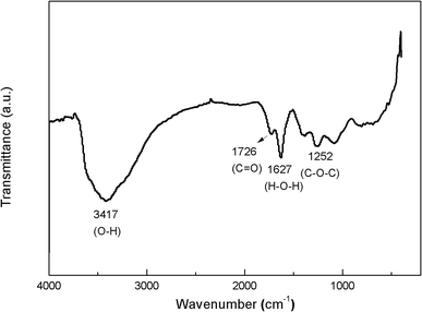
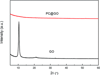
The FT-IR spectra of GO (Fig. 2) clearly show four types of absorption band at 3417.46 cm−1, 1627.41 cm−1, 1726.02 cm−1 and 1252.85 cm−1, corresponding to the existence of O–H, H–O–H, C![[double bond, length as m-dash]](https://www.rsc.org/images/entities/char_e001.gif) O and C–O–C groups, respectively. These results indicate that the oxygen-containing functional groups have been successfully incorporated on GO surface. Fig. 3 shows the XRD patterns of GO and PC@GO. A peak centered at 10.43° in GO pattern corresponds to the interplanar distance of 0.86 nm, which is larger than that of graphite (0.34 nm) due to the incorporation of oxygen-containing functional groups. However, there is no apparent diffraction peak in the pattern of PC@GO, indicating the disorder distribution of exfoliated GO nanosheets after modified by PC.
O and C–O–C groups, respectively. These results indicate that the oxygen-containing functional groups have been successfully incorporated on GO surface. Fig. 3 shows the XRD patterns of GO and PC@GO. A peak centered at 10.43° in GO pattern corresponds to the interplanar distance of 0.86 nm, which is larger than that of graphite (0.34 nm) due to the incorporation of oxygen-containing functional groups. However, there is no apparent diffraction peak in the pattern of PC@GO, indicating the disorder distribution of exfoliated GO nanosheets after modified by PC.
The dispersion of PC@GO in alkaline cement matrix was investigated by means of transmission electron microscopy (TEM). A certain amount of the synthesized PC@GO was dispersed in the simulative cement pore solution (mixed solution of Ca(OH)2, NaOH and KOH, pH = 13.5). After gentle shaking, a drop of solution was dripped onto Cu grids and then dried at room temperature to get rid of the moisture before conducting TEM analysis. It was validated that to keep dispersion in the simulative cement pore solution, the acceptable mass ratio of PC to GO was 10.
2.3. Preparation and characterization of SiO2 NPs suspension and SiO2 NPs/PC@GO hybrid
A certain amount of SiO2 NPs were dispersed in deionized water in the presence of PC using ultrasonic energy for 10 min. To obtain SiO2 NPs/PC@GO hybrid, a certain amount of SiO2 NPs and additional PC (if necessary) were introduced into the synthesized PC@GO solution under electromagnetism stirring. Ultrasonic vibration procedure was carried out for about 10 min to facilitate the dispersion of SiO2 NPs on GO nanosheets. In these suspensions, PC could serve a dual function, dispersing SiO2 NPs as surfactant and reducing water in the subsequent mix procedure as superplasticizer. The two suspensions were diluted 100 times to characterize the dispersion of SiO2 NPs and SiO2 NPs/PC@GO hybrid using TEM images.2.4. Preparation and characterization of cement mortars
![[thin space (1/6-em)]](https://www.rsc.org/images/entities/char_2009.gif) :
:![[thin space (1/6-em)]](https://www.rsc.org/images/entities/char_2009.gif) 3 by mass. Four types of samples were prepared: the reference sample (without any PC@GO or SiO2 NPs) and the samples containing PC@GO and/or SiO2 NPs as SiO2 NPs partial replacement of cement. These samples were labeled as plain-cement sample, GO-cement sample, SiO2-cement sample and hybrid-cement sample, respectively. The concentration levels of nano-additives were varied according to the test scheme. Need of special note was that in SiO2-cement sample and hybrid-cement sample, the dosages of PC were decided on the basis of achieving the required workability. The summarized mix recipes are listed in Table 3.
3 by mass. Four types of samples were prepared: the reference sample (without any PC@GO or SiO2 NPs) and the samples containing PC@GO and/or SiO2 NPs as SiO2 NPs partial replacement of cement. These samples were labeled as plain-cement sample, GO-cement sample, SiO2-cement sample and hybrid-cement sample, respectively. The concentration levels of nano-additives were varied according to the test scheme. Need of special note was that in SiO2-cement sample and hybrid-cement sample, the dosages of PC were decided on the basis of achieving the required workability. The summarized mix recipes are listed in Table 3.
| Cement (g) | Water (g) | Sand (g) | GO (%) | SiO2 (%) | PC (%) | |
|---|---|---|---|---|---|---|
| a The weight percentages of GO, SiO2 NPs and PC are calculated by weight of cement. | ||||||
| Plain-cement | 450 | 202.5 | 1350 | — | — | — |
| GO-cement | 450 | 202.5 | 1350 | 0.01 | — | 0.1 |
| 0.02 | 0.2 | |||||
| 0.04 | 0.4 | |||||
| 0.06 | 0.6 | |||||
| SiO2-cement | 450 | 202.5 | 1350 | — | 0.1 | 0.10 |
| 0.3 | 0.16 | |||||
| 0.5 | 0.30 | |||||
| 1 | 0.50 | |||||
| 1.5 | 0.70 | |||||
| 2 | 0.80 | |||||
| Hybrid-cement | 450 | 202.5 | 1350 | 0.02% | 0.1 | 0.16 |
| 0.3 | 0.24 | |||||
| 0.5 | 0.40 | |||||
| 1 | 0.60 | |||||
| 1.5 | 0.80 | |||||
| 2 | 0.90 | |||||
Ultrasonic pulse velocity measurement was conducted by a pulse meter on hardened cement mortars to characterize air voids. The lightly greased transducers were placed on two sides of the rectangular specimens (40 mm × 40 mm). Three samples were tested for each mix. The pulse velocity was measured at least 3 times for each sample.
Compressive strengths of cement mortars were determined on a compression testing machine with the pressure increasing ratio of 2400 ± 200 N s−1. For each recipe of cement mortar, three samples were tested and the average was taken, the results were evaluated according to the standard deviation.
The microstructure of the hydration products of these cement composites was examined using a field emission scanning electron microscope (SEM) coupled with an energy-dispersive X-ray spectrometer (EDS). The SEM samples were remanet pieces about 5 mm2 from cement mortars which had been tested under compression. They were fixed on a copper stub and coated with a thin layer of Pt before examination.
In order to investigate the degree of cement hydration and pozzolanic reaction in the cement paste by means of thermal gravity analysis (TGA) and differential scanning calorimetry (DSC), four cement pastes (plain-cement sample, GO-cement sample, SiO2-cement sample and hybrid-cement sample) were prepared according to the mix design in Table 3 but without sand. The concentration levels of GO and SiO2 were fixed at 0.02% and 1.0% by weight of cement, respectively. After curing for 3, 7 and 28 days, 40–50 mg fine powders ground from these hardened pastes were heated from room temperature to 1000 °C under nitrogen flow with the heating rate of 10 °C min−1.
XRD analysis was performed to determine the crystalline phase in cement pastes with a scanning rate of 0.02° s−1 in a 2θ range of 5–60° after 28 days curing. The samples were prepared in the same way with those for TGA measurements.
In order to get deeper insights into the effects of nano-additives on cement hydration, heat of hydration measurements were conducted using TAMAIR isothermal conduction calorimeter instrument at a bath temperature of 23 °C, the hydration time was chosen to be 72 h. The test samples were prepared based on the recipe in Table 4. To be weighted accurately, GO was added at the amount of 0.1% by weight of cement (larger than that in cement mortars for mechanical tests) in GO-cement sample and hybrid-cement sample. Since the effects of PC had to be removed from the present analysis, another reference sample containing 1% PC by weight of cement was simultaneously prepared and tested.
| Sample | W/C | GO | SiO2 | PC |
|---|---|---|---|---|
| a The weight percentages are calculated by weight of cement. | ||||
| Reference-1 | 0.45 | — | — | — |
| Reference-2 | 0.45 | — | — | 1.0% |
| GO-cement | 0.45 | 0.1% | 1.0% | |
| SiO2-cement | 0.45 | — | 1.0% | 1.0% |
| Hybrid-cement | 0.45 | 0.1% | 1.0% | 1.0% |
3. Results and discussion
3.1. Dispersion property of PC@GO and SiO2 NPs/PC@GO
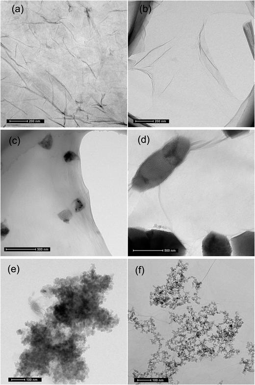
It was found that severe GO agglomeration occurred in simulative cement pore solution (mixed solution of Ca(OH)2, KOH and NaOH, pH = 13.5), due to the interactions between the charged ions (OH−, Ca2+, K+, Na+) and negatively charged GO functional groups that disturb the electrostatic repulsion between GO nanosheets. In this research, chemical alternation of the GO nanosheets surface through creation of covalent bonds with PC was used to exhibit highly dispersed feature in alkaline cement matrix and fulfill effective reinforcement. Experiments have shown that PC@GO can maintain long-term dispersion in the alkaline solution without any discernible precipitation. More information can be found in ref. 8.TEM was used to visualize the morphology and dispersion states of nano-additives. Fig. 4(a) indicates the flaky nature of GO nanosheets. Another striking observation is the crumpled and wrinkled surface texture, implying the overlapped GO layers. While as revealed in Fig. 4(b), PC@GO possesses the smooth surface with curved edges, a feature that is favorable for better interlocking with cement hydration products. The flake-like GO nanosheets instead of agglomerates in Fig. 4(c) and (d) verify the successful dispersion of GO in simulative cement pore solution after modified by PC. The black shadows are inorganic salts in alkaline solution. Fig. 4(e) shows the severe agglomerates of SiO2 NPs although they have been subjected to ultrasonic treatment at the presence of PC. In contrast, the SiO2 NPs tend to distribute uniformly on GO nanosheets with better dispersion, as illustrated in Fig. 4(f).
Fig. 5 shows the dispersion mechanism of PC@GO in alkaline solution. PC is polycarboxylate-based dispersant composed of comb-like copolymers with grafted chains of polyoxyalkylene groups and carboxyl groups.10 The structure of PC is shown in Fig. 5(a). It is deduced that PC macro-molecules have been grafted on GO nanosheets through covalent bonding between PC's carboxyl groups and the oxygen-containing functional groups on GO surface (Fig. 5(b)). This plays a fundamental role in weakening the van der Waals forces between GO layers.8 In the subsequent ultrasonic treatment, GO nanosheets are exfoliated easily and dispersed randomly. Additionally, the strong steric hindrance effects offered by PC lateral chains can mechanically separate the charged ions in cement pore solution away from GO nanosheets. The dispersion mechanism is presented in Fig. 5(c).
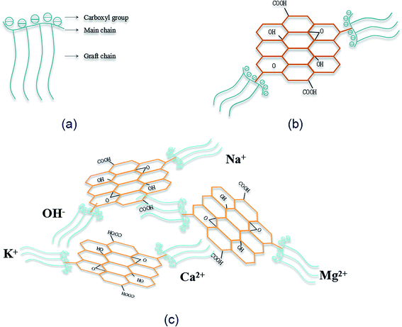 | ||
| Fig. 5 (a) The molecular structure of PC; (b) the structure of PC@GO; (c) the schematic presentation of dispersion mechanism of PC@GO in alkaline solution. | ||
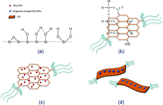
The dispersion mechanism of SiO2 NPs on GO surface is illustrated in Fig. 6. SiO2 NPs tend to attract each other spontaneously to form agglomerates due to the high specific surface energy. As shown in Fig. 6(a), there are a large number of silanol groups on the surface of SiO2 NPs, so the self-condensation of Si–OH groups is another major factor for the aggregation of SiO2 NPs. When SiO2 NPs are introduced into the synthesized PC@GO solution, covalent interactions between Si–OH and functional groups of GO (–COOH, –OH, C–O–C) may take place (Fig. 6(b)).14 As a result, SiO2 NPs are uniformly deposited on GO surface (Fig. 6(c)). The Si–OH groups are expected to ionize in aqueous solution, so the improved dispersion property of SiO2 NPs/PC@GO hybrid is also benefited from the electrostatic repulsion between GO nanosheets covered with negatively charged SiO2 NPs, as depicted in Fig. 6(d).
3.2. Workability
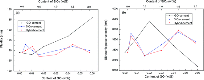
It is generally known that the adequate workability is the prerequisite to ensure the homogeneous of cement-based composites. However, the inclusion of nano-material in cement composites demands available water to wet its large surface and severely degrades the fluidity. This may lead to the increase of viscosity and the remaining of entrapped air in the cement matrix. In this research, mini-slump tests were conducted on fresh cement mortars to investigate the effects of PC@GO and/or SiO2 NPs on the fluidity. Besides, air voids in hardened cement mortars were characterized by ultrasonic pulse velocity measurement. The principle of this test is sending a wave pulse into the cement mortar and measuring the travel time for the pulse to propagate through the mortar, then calculating the velocity of the pulse traveling through the cement mortar.7 When a large air void lies directly in the pulse path, waves will deflect around the void instead of transmitting through it. As a result, the velocity will be lower in the sample with large air voids. The results of mini-slump tests and ultrasonic pulse velocity are listed in Fig. 7.It clearly shows that with the addition of PC@GO, the fluidity diameter increases linearly except the slight decrease for GO-cement sample with 0.01 wt% GO (0.1 wt% PC) by weight of cement. Compared with the fluidity diameter, the ultrasonic velocity of hardened cement mortars containing PC@GO shows very different development tendency. With the addition of PC@GO, the velocity firstly increases, and then sharply decreases after reaching an optimum value.
This creates a very interesting phenomenon: the fluidity of GO-cement sample containing 0.04 wt% GO (0.4 wt% PC) or 0.06 wt% GO (0.6 wt% PC) is relatively high, while the pulse transmission velocity in corresponding sample is much lower than that in GO-cement sample with 0.02 wt% GO, indicating the entrapment of large air voids. This contradiction can be explained in terms of the side-effects of overdosed PC.
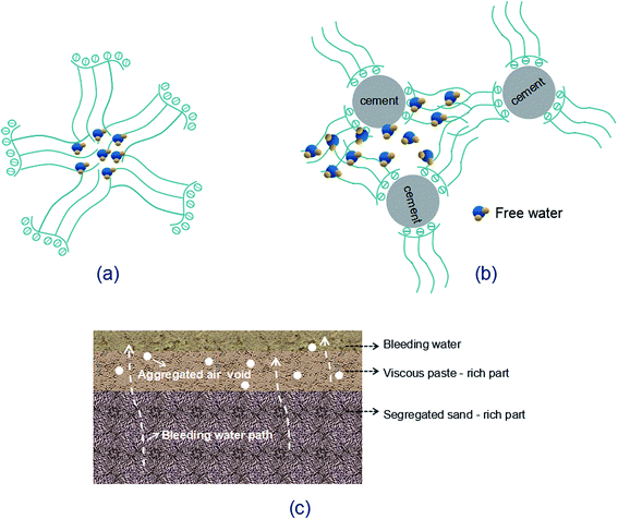
Increasing GO content while the water/cement ratio is held constant may cause difficulty in dispersing GO within alkaline cement matrix. So a large quantity of PC is needed for better dispersion of GO. Although the water/cement ratio used in this research is as large as 0.45, the activity of P.I. 52.5R cement grains is so high that considerable free water is enclosed in the flocculated cement structure. As the PC concentration increases, the redundant graft chains may cause the formation of clusters since the space between either free or the adsorbed PC is not sufficient (Fig. 8(a) and (b)). These clusters will entrap free water, as a result, the inter-particle friction and viscosity significantly increase, leading to the introduction of air voids during the mixing process.12 For GO-cement sample with 0.06 wt% GO (0.6 wt% PC), the side-effects of PC become complicated. A good deal of entrapped water is released from the flocculated cement structure due to the excellent dispersive function of PC. The free water and fine cement particles float to the upper direction, sand particles descend with gravity, resulting in heterogeneous distribution of bleeding water, viscous paste-rich part and segregated sand-rich part, as shown in Fig. 8(c). Moreover, the foam accompanying PC at high dosage may entrain plentiful air in the cement mortar. In the compaction process on a vibration table, the rising air bubbles are embedded in viscous paste-rich part instead of escaping out. These embedded air bubbles gradually aggregate to form large air voids, as presented in Fig. 8(c).
As can be observed, for SiO2-cement samples and hybrid-cement samples, the fluidity diameters are within the range of 170 mm ± 3 mm, the ultrasonic pulse velocities fluctuate from 3780 m s−1 to 3890 m s−1, despite of the concentration levels of SiO2 NPs. The proper workability is accomplished by adjusting the dosage of PC, the released water can well compensate for the water adsorbed by SiO2 NPs without bleeding and segregation.
3.3. Mechanical behavior
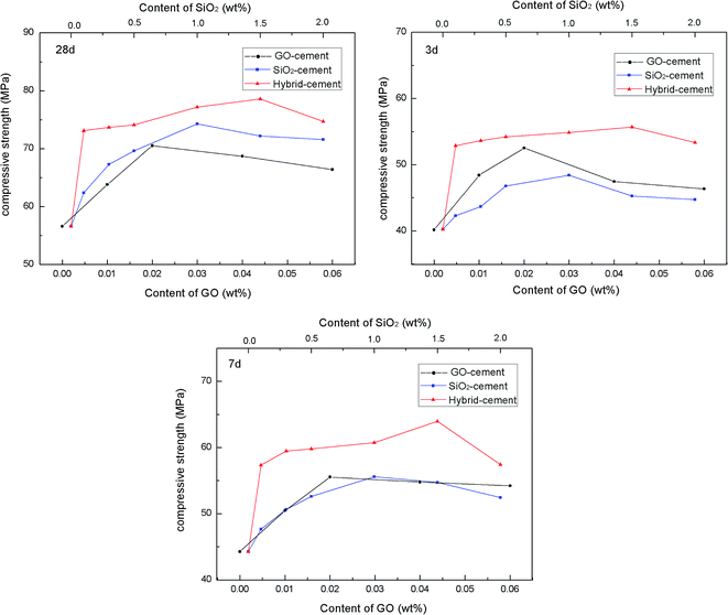
To evaluate the reinforcing effects of PC@GO and/or SiO2 NPs on mechanical behavior of cement composites, the compressive strength tests were performed on these four kinds of cement mortars after curing for 3, 7 and 28 days. The results are presented in Fig. 9. The dosages of nano-additives are calculated by weight of cement.It clearly observes that for GO-cement samples and SiO2-cement samples at all curing ages, the compressive strengths improve progressively as the concentrations of nano-additive increase, but they decrease slightly with higher nano-additive contents. The incorporation of 0.02 wt% GO leads to enhancement factors of 30.68%, 25.43% and 24.58% in compressive strength at 3, 7 and 28 days, respectively. While, up to 1.0 wt% SiO2 NPs shows a similar reinforcement, indicating that GO has better reinforcing effects than SiO2 NPs, especially at early days. The improved mechanical strength of GO-cement samples is attributed to a combination of the accelerated cement hydration, excellent interfacial bonding and refined microstructure.5–8 However, with the addition of 0.04 wt% GO or 0.06 wt% GO, there is a little decrease in compressive strength compared with the maximum value, which may be ascribed to the side-effects of overdosed PC, as described in Section 3.2. The heterogeneous distribution of sand and hydration products, continuous flow paths of bleeding water together with the entrapped large air voids tend to counteract the benefits of GO.11,15 Therefore, too much GO should be avoided in material design.
To further enhance the mechanical behavior of cement composites, SiO2 NPs were introduced to PC@GO aqueous solution to form SiO2 NPs/PC@GO hybrid. The pozzolanic activity of SiO2 coupled with nano-filling effect is in favor of the mechanical enhancement of cement composites.16,17 The effects of SiO2 NPs/PC@GO hybrid on the compressive strength of cement composites have been explored with GO concentration fixed at 0.02 wt% and various SiO2 NPs dosages.
For hybrid-cement samples, it can be clearly observed that with the addition of SiO2 NPs, the compressive strengths are sharply increased from 40.25 MPa to 55.67 MPa at 3 days, after which they decrease with further increasing SiO2 NPs content. The maximum rates of enhancement are 38.31%, 44.47% and 38.89% at 3, 7 and 28 days, respectively, which are much higher than those of cement composites reinforced by a single-promoter (either PC@GO or SiO2 NPs). This result suggests the synergistic effects of SiO2 NPs and PC@GO on cement hydration and microstructure development of hydration products, more in-depth about it will be discussed in the next sections. However, it should be noted that no further increase in compressive strength occurs once the content of SiO2 NPs reaches 2.0 wt%. The aggregates of SiO2 NPs with higher content may create unreacted pockets, leading to stress concentration and giving rise to the decrease trend in mechanical strength.18,19 It is worth while to note that the optimal dosage of SiO2 NPs in hybrid-cement sample is 1.5 wt%, higher than 1.0 wt% in SiO2-cement sample. The elevated threshold of SiO2 concentration is benefited from the better dispersion of SiO2 NPs on GO nanosheets, as evidenced by TEM images in Fig. 4.
3.4. Hydration process
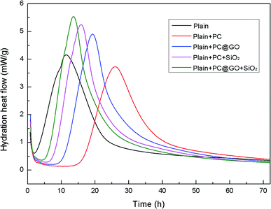
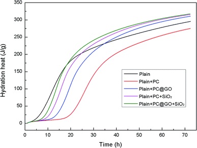
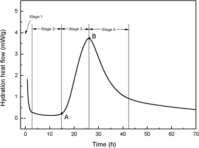
To better understand the effects of PC@GO and/or SiO2 NPs on the hydration process, calorimetry tests were carried out and the results are presented in Fig. 10 and 11. Additionally, the illustration in Fig. 12 is used to analyze the influences of these nano-additives on the hydration kinetics in detail.When cement particles begin to contact with water, there is a burst of heat associated with the initial dissolution of the powder, which is called the pre-induction period (Stage 1). This period is followed by an induction period of low heat out put (Stage 2). At the end of the induction period (Point A), the hydration rate begins to increase and reaches a maximum value (Point B) at the end of the accelerating period (Stage 3). Subsequently, the hydration rate gradually declines (Stage 4).20 The hydration parameters extracted from the heat evolution curves are listed in Table 5, tA and tB indicate the ending point of the induction period and the point of the maximum heat generation rate, respectively. (dQ/dt)A and (dQ/dt)B stand for the heat generation rate at the beginning of the acceleration period and the maximum hydration rate, respectively.21
| Item | tA (h) | tB (h) | (dQ/dt)A (mW g−1) | (dQ/dt)B (mW g−1) |
|---|---|---|---|---|
| Reference-1 | 1.92 | 11.28–11.61 | 0.61 | 4.16 |
| Reference-2 | 16.25 | 25.73–26.22 | 0.39 | 3.73 |
| GO-cement | 11.08 | 19.14–19.42 | 0.62 | 4.90 |
| SiO2-cement | 8.04 | 15.80–15.97 | 0.69 | 5.25 |
| Hybrid-cement | 6.33 | 13.23–13.26 | 0.76 | 5.50 |
In Reference-1 sample, the induction period lasts for only about 1.92 h due to the high activity of fine cement powders. The peak of heat release is found after approximately 11 h. However, in the case of Reference-2 sample, the induction period is prolonged to about 16 h with the presence of PC, the peak is shift to about 26 h and the peak height is decreased compared to Reference-1 sample. Similar results were reported by Zhang Yanrong and Liu Ming.21,22 The polymers covered on cement surface hinder the exchange of water and ions in the system, therefore, the hydration rate is decreased. Besides, the interaction between Ca2+ ions and PC lowers the Ca2+ concentration in the system, preventing the nuclei of hydration products.23,24
Fortunately, the retardation effects of PC can be largely compensated by the addition of nano-additives. It is apparent that the time required to reach the maximum rate is reduced and the peak rate is simultaneously increased in both GO-cement paste and SiO2-cement past with respect to Reference-2. The oxygen functional groups on GO surface can provide preferential nucleation sites during the hydration, which is responsible for the accelerated cement hydration. SiO2 NPs with pozzolanic activity and high specific surface area also promote the cement hydration by nucleus effects. The value of tA is further shortened to about 6 h in hybrid-cement sample, and the maximum heat rate is increased by a factor of 47% compared with Reference-2 paste. These results suggest that the better dispersed SiO2 NPs/PC@GO hybrid can generate more reactive nucleation sites for the growth of hydration products, giving an early and higher heat release peak.
The cumulative heat curves of hydration over a period of 72 h are shown in Fig. 11. The amount of heat released by cement hydration can partially reflect the hydration degree. It is clearly shown that the hydration heat reaches a relative stable state after 60 h. The total heat of hydration in Reference-2 sample containing PC is slightly lower than that in Reference-1 sample due to the retardation effect of PC. In contrast, the samples incorporating nano-additives exhibit higher total heat, indicating the accelerated degree of cement hydration.
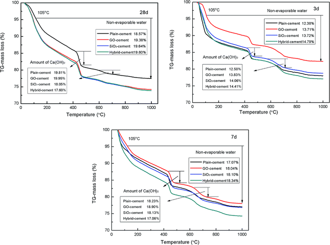
The results of thermal gravity analysis of cement pastes during 3, 7 and 28 days are presented in Fig. 13. According to the TGA curves, the samples begin to lose moisture below 100 °C, which is attributed to the escape of evaporable water and part of bound water. In the range of 120–150 °C the broad peak is observed due to the existence of ettringite and C–S–H gels. The second main mass loss between 400–500 °C is attributed to the dehydration of Ca(OH)2. There is another small mass loss at about 600–700 °C due to the decomposition of CaCO3 resulting from uncontrolled carbonation.
The non-evaporable water content is employed to estimate the degree of cement hydration, which is determined according to the following equation:25
| Mwater = M105°C − M1000°C | (1) |
| MCH = 74/18 × WLCH + 74/44 × WLCaCO3 | (2) |
The contents of non-evaporable water in GO-cement samples and SiO2-cement samples are consistently at a higher proportion than those in plain-cement samples at all ages, which is taken as the evidence pertaining to the role of GO and SiO2 in accelerating cement hydration. Moreover, the degree of cement hydration is further enhanced with the addition of SiO2 NPs/PC@GO hybrid, exhibiting the highest non-evaporable water contents (at 28 days, the value is slightly lower than that in SiO2-cement sample), especially at early days. These results are in good agreement with the conclusions obtained by calorimetry measurement.
With the hydration of alite (C3S) and belite (C2S) phases, the precipitation of calcium hydroxide increases, its quantity can be estimated as the degree of cement hydration. However, CH crystals tend to precipitate as hexagonal plates with different orientations and weak cohesive forces, which impose negative effects on mechanical strength of cement composites. In this research, it is expected to refine the structure or reduce the amount of CH crystals by adding nano-additives. SiO2 NPs are reported to have the ability to consume the non-strength contributing CH crystals to produce stable C–S–H gels.16,17
It is observed that the contents of CH in SiO2-cement sample and hybrid-cement sample are larger than those in plain-cement sample and GO-cement sample at 3 days. A reasonable interpretation is that the nucleus effects of SiO2 NPs are dominant at early ages, few SiO2 NPs participate in pozzolanic reaction. While after curing for 7 and 28 days, in the cases of SiO2-cement samples and hybrid-cement samples, there are less CH crystals with respect to plain-cement samples. Apparently, the hybrid-cement samples exhibit consistently lower proportions of CH than those in SiO2-cement samples at 7 and 28 days, indicating the higher degree of pozzolanic reaction. The limited pozzolanic reaction in SiO2-cement samples should be attributed to the severely agglomerated SiO2 particles (as shown in Fig. 4(e)). While in hybrid-cement samples, the uniformly dispersed SiO2 NPs on GO nanosheets (as illustrated in Fig. 4(f)) are advantageous to give pozzolanic activity in full play. Another factor responsible for the improved degree of pozzolanic reaction is the hybrid structure of SiO2 NPs and GO, which makes the ionic transfer from CH crystals nucleated and developed on GO nanosheets to SiO2 NPs more efficient.
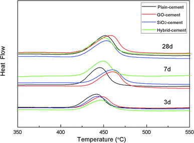
DTA investigation was focused on CH, which is the main product of cement hydration. The results of DTA measurement of cement pastes after curing for 3, 7 and 28 days are given in Fig. 14.
It is reported that the decomposition temperature of CH crystals is proportional to their sizes.22 At 3 days, the decomposition temperatures of CH crystals in cement pastes containing nano-additives are much higher than that in reference sample, indicating the larger CH crystals due to the nucleus effects provided by SiO2 NPs and/or GO. With the increasing of curing time, the decomposition temperature of CH crystals in SiO2-cement sample is lower than that in GO-cement sample, though both samples have the similar degree of cement hydration. Additionally, samples containing SiO2 NPs/PC@GO hybrid present further decreased decomposition temperature of CH. The dispersed SiO2 NPs with high pozzolanic activity consume CH crystals and diminish their size simultaneously. The DSC results are well consistent with those from thermal gravity analysis in the previous discussion.
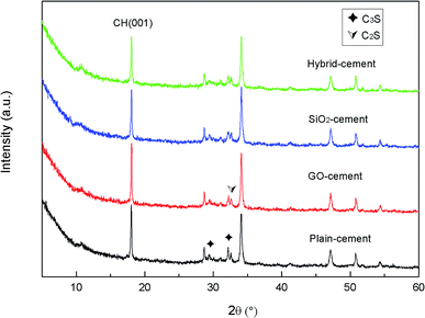
XRD analysis was performed on the powders of cement composites to study the effects of GO nanosheets and/or SiO2 NPs on the qualitative and quantitative of various crystalline phases after curing for 28 days. The XRD patterns are shown in Fig. 15.
Note that the weight fractions of GO and SiO2 NPs are so little, there are no peaks corresponding to them in the XRD patterns. The unhydrated silicates of C2S (2θ = 32.7°) and C3S (2θ = 29.5°, 32.2° θ) are detected in the XRD patterns. The lower intensities of peaks referring to C2S and C3S in samples containing nano-additives with respect to plain-cement sample suggest the quicker consumption of cement components. This can be viewed as the testimony towards the accelerated cement hydration in these samples. Peaks located at 18.3°, 34.2°, 47.1° and 50.1° correspond to calcium hydroxide, the major crystalline phase of cement hydration products. The peak at 18.3° is often used as an indicator of the degree of cement hydration and pozzolanic reaction. The intensities of the peak at 18.3° are found to increase in GO-cement sample, while decrease in SiO2-cement sample and especially decrease in hybrid-cement sample, with respect to the sample without any GO or SiO2 NPs. This partially supports the conclusion derived from thermal gravity analysis that the SiO2 NPs/PC@GO hybrid harbors the ability to promote the pozzolanic reaction. However, the investigation of the main product of cement hydration and pozzolanic reaction, C–S–H, is limited by XRD due to its amorphous structure. In this research, the characterization of C–S–H was carried out with the aids of SEM, which will be discussed in detail in the next section.
3.5. Microstructure
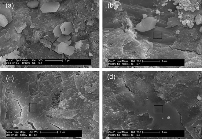
To investigate the effects of GO nanosheets and/or SiO2 NPs on the microstructure of cement hydration products, SEM images were taken from the fracture surfaces of the cement mortars. The results are shown in Fig. 16. In order to obtain more information about the hydration products, the chemical element composites of the areas in black rectangles in corresponding SEM images were determined by EDS and the results are listed in Table 6.| Element percentage (at%) | |||||||||
|---|---|---|---|---|---|---|---|---|---|
| C | O | Ca | Si | Al | S | Na | K | Fe | Mg |
| 0.87 | 30.54 | 48.52 | 7.75 | 4.56 | 1.50 | 2.83 | 2.15 | 1.28 | — |
| — | 62.25 | 35.49 | 1.66 | — | 0.61 | — | — | — | — |
| — | 56.38 | 26.27 | 12.92 | 1.03 | 1.32 | — | — | 0.75 | 0.86 |
| — | 36.84 | 46.61 | 14.43 | 0.65 | — | — | 0.21 | 0.61 | 0.65 |
Hexagonal plates with loose structure are predominant in Fig. 16(a), the element percentage of this flake-like hydration crystal is close to CH. After the evaporation of free water in cement matrix, the liberated CH flakes leach out in the local region with a higher water/cement ratio. These crystals are responsible for the brittleness of cement composites. A great number of merged plates with element components closing to CH are formed with the presence of GO. These crystals are more compact and regular distributed (Fig. 16(b)). The result suggests that the microstructure of hydration products is refined by GO. Further more, the large surface areas of uniformly distributed GO nanosheets demand free water to wet their surface, as a result, the evaporation of free water is inhibited and the precipitation of flake-like CH crystals is prevented. In SiO2-cement sample and hybrid-cement sample, with the addition of pozzolanic SiO2 NPs, the CH crystals are hardly to recognize, the element components of the dense structure in the selected areas in Fig. 16(c) and (d) are close to the semi-crystalline C–S–H gels. The C–S–H gels in hybrid-cement sample are well-developed and have undergone fusion to form the extremely compact microstructure. This is profit from the higher degree of pozzolanic reaction offered by the hybrid structure of GO nanosheets and SiO2 NPs.
3.6. Mechanism analysis of synergistic effects of SiO2 NPs/PC@GO hybrid
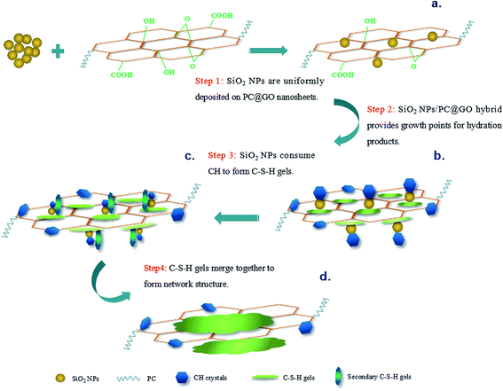
Based on the above results and discussion, possible mechanisms of synergistic effects of SiO2 NPs/PC@GO hybrid are proposed, and a schematic diagram is shown in Fig. 17.GO nanosheets are first modified by PC to ensure better dispersion in alkaline cement matrix. SiO2 NPs used in this research are hydrated silica with silanol groups on their surface. The high surface energy and self-condensation of Si–OH groups make SiO2 NPs attract each other to form aggregates. When SiO2 NPs are introduced into the synthesized PC@GO solution, they are uniformly deposited on GO nanosheets through covalent interaction between Si–OH and functional groups of GO (Fig. 17(a)). In the hydration process, the active SiO2 NPs/PC@GO hybrid provides profitable growth points for hydration products. Then the hydration reactions continue to take place at the growth points, as a result, the hydration products develop on the surface of SiO2 NPs/PC@GO hybrid instead of on the unhydrated cement grains (Fig. 17(b)). This seeding effect of SiO2 NPs/PC@GO hybrid can accelerate the cement hydration to yield compact microstructure. Along with the hydration, SiO2 NPs with pozzolanic activity gradually react with CH crystals to form high density C–S–H gels, the most desirable products of cement hydration and greater contributors to mechanical strength (Fig. 17(c)). The hybrid structure of SiO2 NPs and PC@GO makes the ionic transfer in the hydration system more efficient, as a result, the C–S–H gels developed around GO nanosheets tend to merge together with the secondary C–S–H gels, leading to the formation of the network structure (Fig. 17(d)).
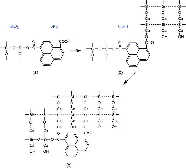
In addition to the higher degree of cement hydration and pozzolanic reaction, the improved chemical bonding among SiO2 NPs/PC@GO hybrid and cement matrix is also achieved. Fig. 18(a) describes the covalent bonding between SiO2 NPs and GO nanosheets (taking Si–OH and –COOH for instance). In the hydration process, the surface functional groups of GO first act as nucleating sites for the hydration products. This is followed by the development of chemical reaction between the functional groups and hydration products (Fig. 18(b)).26,27 As the pozzolanic reaction continues, the secondary C–S–H gels tend to fuse together through covalent bonding with the C–S–H gels around GO nanosheets. Finally, the cross-linking structure of [SiO2–GO–CSH] is formed using GO as the bridge (Fig. 18(c)). This cross-linking structure can alleviate stress concentration and facilitate the load-transfer uniformly throughout cement matrix, which is favorable for the improvement of mechanical strength.
4. Conclusions
In this paper, the co-effects of SiO2 NPs/PC@GO hybrid on the compressive strength of cement composites have been investigated. Additionally, the cement hydration characteristics with the addition of nano-additives (SiO2 NPs and/or PC@GO) are also examined by means of isothermal calorimetry, TGA, DSC, XRD, SEM and EDS.The results show that SiO2 NPs tend to uniformly distribute on the surface of GO nanosheets through covalent interactions between Si–OH groups and GO functional groups. The addition of SiO2 NPs/PC@GO hybrid (1.5% SiO2 and 0.02% GO by weight of cement) results in 38.31%, 44.47% and 38.89% enhancement of cement compressive strength at 3, 7 and 28 days, higher than that of cement composites reinforced by a single-promoter (either PC@GO or SiO2 NPs). Our results demonstrate that the addition of SiO2 NPs/PC@GO hybrid can accelerate the cement hydration, improve the degree of pozzolanic reaction and reduce the slack packed CH crystals. Based on these results, we conclude that the synergistic effects of SiO2 NPs/PC@GO hybrid are considered to be a combination of better dispersed nano-additives, higher degree of pozzolanic reaction and the cross-linking structure of [SiO2–GO–CSH].
This work has shed light on the use of hybrid structure of 0D and 2D nano-materials as reinforcement for cement composites. In the future, the effects of SiO2 NPs/PC@GO hybrid on the microstructure, flexural toughness as well as durability of cement composites will be systematically studied.
Acknowledgements
This work was supported by the Key Program of the National Natural Science Foundation of China [grant numbers 51438003]; and the National Basic Research Program of China [grant numbers 2015CB655105].References
- S. Chuah, Z. Pan, J. G. Sanjayan, C. M. Wang and W. H. Duan, Construct. Build. Mater., 2014, 73, 113–124 CrossRef.
- S. Sharma and N. C. Kothiyal, RSC Adv., 2015, 5, 52642–52657 RSC.
- C. Lu, Z. Y. Lu, Z. J. Li and C. K. Y. Leung, Construct. Build. Mater., 2016, 120, 457–464 CrossRef.
- Y. W. Zhu, S. Murali, W. W. Cai, X. S. Li, J. W. Suk, J. R. Potts and R. S. Ruoff, Adv. Mater., 2010, 22, 3906–3924 CrossRef CAS PubMed.
- K. Gong, Z. Pan, A. H. Korayem, L. Qiu, D. Li, F. Collins, C. M. Wang and W. H. Duan, J. Mater. Civ. Eng., 2015, 27, A4014010 CrossRef.
- S. H. Lv, T. Sun, J. J. Liu and Q. F. Zhou, CrystEngComm, 2014, 16, 8508–8516 RSC.
- Z. Pan, L. He, L. Qiu, A. H. Korayem, G. Li, J. W. Zhu, F. Collins, D. Li, W. H. Duan and M. C. Wang, Cem. Concr. Compos., 2015, 58, 140–147 CrossRef CAS.
- L. Zhao, X. L. Guo, C. Ge, Q. Li, L. P. Guo, X. Shu and J. P. Liu, Construct. Build. Mater., 2016, 113, 470–478 CrossRef.
- F. Collins, J. Lambert and W. H. Duan, Cem. Concr. Compos., 2012, 34, 201–207 CrossRef CAS.
- C. A. Anagnostopoulos, Construct. Build. Mater., 2014, 50, 162–168 CrossRef.
- H. J. Du and S. D. Pang, Cem. Concr. Res., 2015, 76, 10–19 CrossRef CAS.
- A. Yahia, Cem. Concr. Res., 2011, 41, 230–235 CrossRef CAS.
- F. Sanchez and K. Sobolev, Construct. Build. Mater., 2010, 24, 2060–2071 CrossRef.
- B. Ramezanzadeh, Z. Haeri and M. Ramezanzadeh, Chem. Eng. J., 2016, 303, 511–528 CrossRef CAS.
- J. G. Han and K. J. Wang, Construct. Build. Mater., 2016, 115, 240–246 CrossRef.
- Q. Ye, Z. N. Zhang, D. Y. Kong and R. S. Chen, Construct. Build. Mater., 2007, 21, 539–545 CrossRef.
- P. K. Hou, J. S. Qian, X. Cheng and S. P. Shah, Cem. Concr. Compos., 2015, 55, 250–258 CrossRef CAS.
- H. Li, H. G. Xiao, J. Yuan and J. P. Ou, Composites, Part B, 2004, 35, 185–189 CrossRef.
- R. Hosseinpourpia, A. Varshoee, M. Soltani, P. Hosseini and H. Ziaei Tabari, Construct. Build. Mater., 2012, 31, 105–111 CrossRef.
- M. H. Zhang, K. Sisomphon, T. S. Ng and D. J. Sun, Construct. Build. Mater., 2010, 24, 1700–1707 CrossRef.
- Y. R. Zhang, X. M. Kong, Z. B. Lu, Z. C. Lu and S. S. Hou, Cem. Concr. Res., 2015, 67, 184–196 CrossRef CAS.
- M. Liu, J. H. Lei, L. P. Guo, X. D. Du and J. S. Li, Thermochim. Acta, 2015, 613, 54–60 CrossRef CAS.
- D. Jansen, J. Neubauer, F. Goetz-Neunhoeffer, R. Haerzschel and W. D. Hergeth, Cem. Concr. Res., 2012, 42, 327–332 CrossRef CAS.
- H. Uchikawa, S. Hanebara and D. Sawaki, Cem. Concr. Res., 1997, 27, 37–50 CrossRef CAS.
- J. I. Escalante-Garcia, Cem. Concr. Res., 2003, 33, 1883–1888 CrossRef CAS.
- Z. Y. Lu, D. S. Hou, L. S. Meng, G. X. Sun, C. Lu and Z. J. Li, RSC Adv., 2015, 5, 100598–100605 RSC.
- G. Y. Li, P. M. Wang and X. H. Zhao, Carbon, 2005, 43, 1239–1245 CrossRef CAS.
| This journal is © The Royal Society of Chemistry 2017 |

