 Open Access Article
Creative Commons Attribution 3.0 Unported Licence
Preparation of a NbN/graphene nanocomposite by solution impregnation and its application in high-performance Li-ion hybrid capacitors†
Zhen-Kun Chenab,
Jun-Wei Langb,
Ling-Yang Liub and
Ling-Bin Kong *a
*a
aState Key Laboratory of Advanced Processing and Recycling of Non-ferrous Metals, School of Materials Science and Engineering, Lanzhou University of Technology, Lanzhou 730050, PR China. E-mail: konglb@lut.cn; Fax: +86-931-2976578; Tel: +86-931-2976579
bLaboratory of Clean Energy Chemistry and Materials, State Key Laboratory of Solid Lubrication, Lanzhou Institute of Chemical Physics, Chinese Academy of Sciences, Lanzhou 730000, PR China
First published on 5th April 2017
Abstract
Lithium-ion hybrid capacitors (LIHCs) have received a mushrooming amount of attention due to their high power density and energy density. However, the imbalanced dynamics between positive and negative electrodes limit their practical applications. Thus, in order to develop a kind of anode material with high power, we report a simple synthesis technology of a NbN nanoparticles/graphene nanosheets (NbN/GNSs) nanocomposite with fast Li insertion/extraction properties. Through a facile solution impregnation followed by annealing treatment, we get a freestanding layer-stacked structure combining 2D graphene nanosheets and 0D NbN nanoparticles. It shows a high reversible capacity of ≈ 450 mA h g−1 at 0.1 A g−1, moreover, as a result of the fast pseudocapacitive performance, it also shows a remarkable rate capability and cycle stability (90% capacity retention at 5 A g−1 after 10![[thin space (1/6-em)]](https://www.rsc.org/images/entities/char_2009.gif) 000 cycles). Meanwhile, the LIHC with a NbN/GNSs anode and activated polyaniline derived carbon (APDC) cathode delivers the maximum energy density of 136 W h kg−1, and the highest power density of 25 kW kg−1 as well as a stable cycle life in the potential range of 1.0–4.0 V.
000 cycles). Meanwhile, the LIHC with a NbN/GNSs anode and activated polyaniline derived carbon (APDC) cathode delivers the maximum energy density of 136 W h kg−1, and the highest power density of 25 kW kg−1 as well as a stable cycle life in the potential range of 1.0–4.0 V.
1 Introduction
With the increasing of the fossil energy depletion and environmental pollution, it is particularly urgent to find renewable green energy to replace the traditional primary energy. The development of renewable energy (like wind and solar energy) has put forward higher requirements than the traditional energy storage devices. As the most widely applicable energy storage devices, lithium-ion batteries (LIBs) and supercapacitors (SCs) have received wide attention and discussion.1–4 However, obvious defects caused by their different charge storage mechanisms exist in both of them. LIBs commonly can provide energy density as high as 150–200 W h kg−1, but are restricted by their low power density (below 1000 W kg−1) and poor cycle life (usually less than 1000 cycles).5 In contrast, SCs can provide much higher power density (10 kW kg−1), long cycle life (about 1 × 10⁵ cycles) and fast charge–discharge processes (within seconds),6 however suffer from much lower energy density (only 3–6 W h kg−1).7–9 Based on this, a large number of researchers have turned their attention to the lithium ion hybrid capacitors (denoted as LIHCs).LIHC is a new energy storage device which combines the advantages of LIBs and the SCs.10–14 It respectively utilizes the nonfaradaic capacitive material and battery-type material as the cathode and anode electrode in organic electrolytes system.15–18 Different charge storage mechanisms between the sluggish faradaic anode and the rapid capacitive cathode cause the imbalanced kinetics, and due to this, the rate performance and cyclic stability of LIHC are still less than satisfactory. Therefore, in order to improve the two drawbacks of LIHCs, effective ways are developed such as utilizing a capacitive cathode material with high specific capacity and anode material with fast reversible insertion/extraction reaction. Among the possible electrode materials, carbon material can act as an ideal cathode because of its high theoretical specific capacity and excellent cycle performance. However, the rate performance of anode materials is far less than expected due to the limitation of sluggish redox reaction.19,20
In order to improve the kinetics and capacity of anode, some electrode materials with pseudocapacitive behaviors are proposed, such as Nb2O5,13,14,21 V2O5,22 TiO2 7,23 and MoO3.24,25 Those materials can provide intercalation or surface redox pseudocapacitance. However, they usually undergo poor electrical conductivity and the relatively high redox potential (>1.5 V versus Li/Li+) which may reduce the operating voltage window (usually below 3.2 V) of the assembled LIHCs and then result in an unnecessary loss of energy density. Therefore, it is extremely urgent to devise a kind of anode material with high electrical conductivity and rate capability.
Through our previous work,26 we found that NbN anode has a relatively high electronic conductivity (∼9.6 S cm−1) and excellent cyclic stability in LIBs. It also has a wide lithiation potential (0.01–3 V) which may effectively expand the potential window of LIHC. However, the specific capacity of NbN anode is only 300 mA h g−1 at current density of 0.1 A g−1. The low capacity is not satisfactory for the anode of LIHC and it need further improvement in charge storage. In this paper, we prepared the layer-stacked NbN/GNSs structure by solution impregnation method. This special structure was designed based on the following aspects: on one hand, the graphene nanosheets not only prevent NbN nanoparticles from agglomeration during growth, but also help to improve the capacity of the final composite. On the other hand, this stacked layer-by-layer structure can shorten the transport length for both electrons and Li ions, and will further minimize the effect of low ionic diffusivity, and better accommodate the strain during Li ions intercalation/deintercalation in active materials. As a result, the final composites obtained a considerable improvement in specific capacity (450 mA h g−1 at 0.1 A g−1) with a fast pseudocapacitive charge storage process. By using the NbN/GNSs composite as the anode and activated carbon as the cathode, we fabricated a LIHC with a high energy density of 136 W h kg−1 and a high power density of 25 kW kg−1. This high-performance LIHC may be applied in electric vehicles and large-scale energy-storage systems in the future.
2 Results and discussion
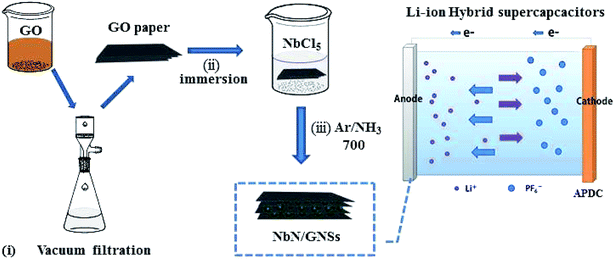
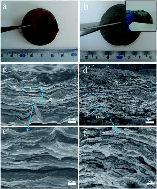
The NbN/GNSs composite paper was prepared through a facile synthesis procedure with three steps, which are illustrated in Fig. 1, (i) a certain amount of graphene oxide powder was added in the deionized water, and after ultrasonic treatment, the stable dispersion solution was obtained. The paper-like GO substrate with a brown surface and ca. 45 mm diameters is fabricated by vacuum filtration of the uniform dispersion (Fig. 2a). (ii) GO paper was immersed in a precursor solution (aqueous solution containing niobium pentachloride and oxalic acid dihydrate) for 24 h, the solution slowly infiltrated into the 2D gaps between GO layers by capillary force due to the hydrophilic nature of GO.27 After being washed with deionized water and dried under 60 °C in vacuum, oxide precursor solid was formed in GO sheets, which formed alternate layer-by-layer structure of GO and oxide precursor solids. (iii) After further ammonification of the as-assembled papers at 700 °C in NH3 and Ar flow, the high crystalline cubic phase of NbN was obtained. From the thermogravimetric analysis (Fig. S1†), the NbN loading in the NbN/GNSs composite papers is 14.5 wt%. It was found that the amount of niobium nitride in the final composite maintains at 14.5% by increasing the impregnation time. In order to better highlight the role of niobium nitride in the composite, we have adopted the maximum niobium nitride load in all of the following samples. The obtained NbN/GNSs can still maintain the complete paper-like structure and exhibit good flexible properties (Fig. 2b).The morphology of the composite paper can be clearly observed by scanning electron microscope (SEM), Fig. 2c and e show the cross-sectional SEM images of the GO paper. It displays a layer-stacked structure with a thickness of ∼4 μm, this special structure provides a large number of tiny 2D gaps. A series of precursor solutions can drive into the gaps and form inorganic nanoparticles. Fig. 2d and f show the SEM images of NbN/GNSs composite paper. It still maintains a layer-stacked structure after solution impregnation and heat-treatment process. Compare with the GO paper, it possesses a relatively loose structure with some open 2D channels and provides transport channels for the electrolyte to spread to the inner active nanoparticles.
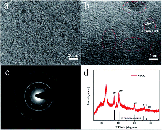
The TEM image (Fig. 3a) shows the uniform distribution of NbN particles in graphene layers. The high-resolution TEM (HR-TEM) image (Fig. 3b) shows that the sizes of NbN nanoparticle are in the range of 5–10 nm, which are highly advantageous for application as a high-power electrode because of the shortened diffusion length for Li ion in the active materials.27 Fig. 3b also exhibits the clear lattice fringes with a spacing of 0.25 nm, which is in good agreement with spacing of (111) plane of cubic crystal NbN. The obvious electron diffraction rings in Fig. 3c also proves that NbN nanoparticles are highly crystalline. The broad peak centered at 2θ ≈ 25° in Fig. 3d corresponds to the graphitic structure from graphene and the remaining peaks at 35, 41, 59, 71, and 74° match well with (111), (200), (220), (311), and (222) lattice plane of the cubic NbN (JCPDS no. 38-1155).
Additionally, the X-ray photoelectron spectroscopy (XPS) further proves the coexistence of niobium, nitrogen, carbon and oxygen elements in NbN/GNSs sample (Fig. S2†). The O signal from the nitrided product is probably due to surface oxidization and the remaining oxygen-containing functional groups after sintering treatment, the O/C ratio in graphene paper is 14.7% by comparing the area of oxygen peak and the carbon peak in XPS spectrum. As shown in Fig. S2b,† the characteristic niobium nitride Nb 3d doublet is observed at 207 eV and 204.9 eV, revealing that the Nb 3d peak is composed of the spin–orbit doublet of Nb 3d3/2 and Nb 3d5/2. Besides, the peak of 210.1 eV can be attributed to Nb–N–O in niobium nitride.28,29 The high-resolution N 1s spectrum (Fig. S2c†) can be divided into to three sub-peaks due to the spin–orbit coupling. The peaks at 400.1 eV and 397.6 eV are attributed to pyrrolic-N and Nb–N, respectively. The high-resolution C 1s spectrum (Fig. S2d†) can be divided into to three sub-peaks. The main peak at 284.6 eV is attributed to sp2-hybridized graphite-like carbon (C–C sp2), and the peaks centered at 286.6 and 289 eV can be ascribed to surface oxygen and nitrogen groups (designated as C–N, O![[double bond, length as m-dash]](https://www.rsc.org/images/entities/char_e001.gif) C–O, respectively).
C–O, respectively).
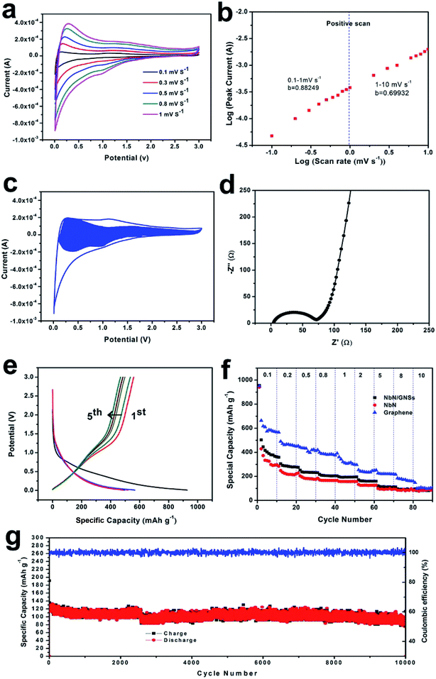
In order to study the electrochemical mechanism of NbN/GNSs composite electrodes, half-cells were prepared using a 2032-type coin cell with lithium metal as the counter and reference electrodes. As shown in Fig. 4a, cyclic voltammetry (CV) tests were performed at various scan rates from 0.1 to 1 mV s−1 to investigate energy storage mechanism of the NbN/GNSs electrode. The broad cathodic and anodic peaks are observed in the potential range between 0.01 and 3.0 V (vs. Li/Li+). The cathodic peaks mainly appear in the potential range of 0.1–0.5 V in the discharging process, while anodic peak appears at 0.1 V in the charging process. This phenomenon is similar to those of pseudocapacitive material (e.g., Nb2O5, RuO2), suggesting a series of insertion and extraction reactions of NbN with Li ions during the discharge–charge process. Referring to the previously reported nitrides,12,30 the reaction mechanism can be expressed as the following equation:
| NbN + xLi+ + 3e = 4LixNbN | (1) |
Because of the unique behavior of pseudocapacitive material, the current in the CV tests are directly proportional to the sweep rates, obeying the power law:
| i = avb | (2) |
Fig. 4b presents a plot of log(i) versus log(v) from 0.1 to 10 mV s−1 for anodic peaks (the corresponding CV curves from 1 to 10 mV s−1 is shown in Fig. S3†). Within the sweep rates ranging from 0.1 to 1 mV s−1, the b-value for the anodic peaks is about 0.88, and this demonstrates that the kinetics of NbN/GNSs is surface-controlled with quite more faster Li+ intercalation process.12,23,31 This faster kinetics also explain why NbN/GNSs composite provide outstanding rate capability and good cycling performance, especially under high current density. With raising of the sweep rates, b-value gradually decreases (1 to 10 mV s−1: b = 0.70), and it might arise from the diffusion constraint/limitation and/or an increase of the ohmic contribution.31
In order to further understand the role of NbN/GNSs in the improved rate capability and specific capacity, we quantitatively separated the current (i) into pseudocapacitive effects (k1v) and diffusion-limited elements (k2v1/2).24,32 The corresponding equation is:
| i(V) = k1v + k2v1/2 | (3) |
| i(V)/v1/2 = k1v1/2 + k2 | (4) |
In order to prove that the NbN/GNSs is mainly controlled by the pseudocapacitive in the lithium ion storage, we have further carried out the electrical impedance spectroscopy (EIS) measurements (Fig. 4d). According to the high frequency semicircle, the as-prepared NbN/GNSs paper present a low charge-transfer resistance (Rct) (about 70 Ω). The low frequency curve corresponding to the Warburg impedance has a slope lager than 1, indicating the Li ion intercalation behaviors of electrodes is not limited by the diffusion process.33 From the galvanostatic charge–discharge (GCD) voltage profiles of NbN/GNSs tested at 0.1 A g−1 in voltage range from 0.01 to 3.0 V (vs. Li/Li+) (Fig. 4e), we can see that the charge/discharge curves have no obvious platform and well matches with the CV curves, this further proves the pseudocapacitive charge storage behavior of the NbN/GNSs. After the first cycle, there exists an obvious irreversible capacity loss, and it could be attributable to (i) the formation of a solid–electrolyte interphase (SEI), (ii) irreversible side reactions inside nanostructured electrodes, and/or with functional groups on graphene.34,35 There is still a reversible capacity of ∼450 mA h g−1 remaining at the second cycle. The rate capability of the NbN/GNSs electrode was evaluated by charge/discharge experiments at various current densities (Fig. 4f). When the discharge current density increased from 1, 2, 5, 8, to 10 A g−1, the reversible discharge capacity of NbN/GNSs electrode varied from 250, 200, 136, 110, to 100 mA h g−1. Moreover, the coulombic efficiencies of the NbN/GNSs composite were close to 100%. Compared with the discharge capacity at 1 A g−1, the NbN/GNSs electrode yield retained 54% capacity at 5 A g−1 and 40% at 10 A g−1. It is worth noted that the NbN/GNSs composite delivers higher capacity than pure NbN at various rates from 0.1 A g−1 to 8 A g−1. Based the comparison of specific capacity of NbN and graphene under different current densities, we infer that the improvement of capacity benefits from the contribution of graphene. We carried out a cyclic test at the current density of 5 A g−1 (Fig. 4g). After 10![[thin space (1/6-em)]](https://www.rsc.org/images/entities/char_2009.gif) 000 cycles, the capacity retention rate is 90%, showing the excellent cycle performance of NbN/GNSs at high current density.
000 cycles, the capacity retention rate is 90%, showing the excellent cycle performance of NbN/GNSs at high current density.
For further verifying the favorable application of NbN/GNSs in the high power LIHC, we have constructed a LIHC by using NbN/GNSs as the anode and APDC (activated polyaniline derived carbon, prepared on the basis of our previous work,36 and its electrochemical properties are shown in Fig. S4†) as the cathode, and LiPF6 in ethylene carbonate (EC)/dimethyl carbonate (DMC)/diethyl carbonate (DEC) as electrolytes. Before fabricating the LIHC, the NbN/GNSs was pre-activated for 10 cycles at 100 mA g−1 in the Li half-cell in order to improve the coulombic efficiency of the anode material. Considering the charge balance between the cathode and anode, the mass ratio between cathode and anode was optimized, and the best ratio between NbN/GNSs and APDC was 1![[thin space (1/6-em)]](https://www.rsc.org/images/entities/char_2009.gif) :
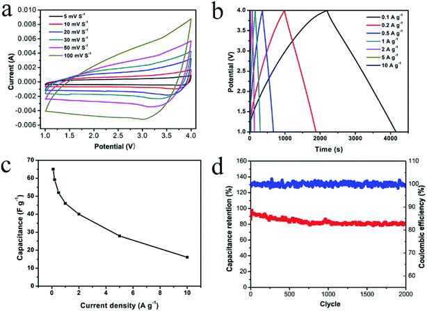
:![[thin space (1/6-em)]](https://www.rsc.org/images/entities/char_2009.gif) 1 (as shown in Fig. S5 and S6†). Due to the low redox potential of the NbN/GNSs anode,19,37 the voltage window of the LIHC can be controlled between 1.0 and 4.0 V and obtain a maximum power and energy densities (the choice detail is shown in Fig. S7†). Fig. 5a shows CV profiles of the LIHC at various scan rates from 5 to 100 mV s−1, and the LIHC exhibits a relatively quasi-rectangular shape, indicating that the fast Li+ intercalation reaction of NbN/GNSs matching the electrolyte ion transport at the APDC-electrolyte interface.13 In Fig. 5b, the GCD curves of the LIHC at current densities from 0.1 to 10 A g−1 (the current densities were based on the total mass of active material in both anode and cathode) also exhibit the symmetric quasi-triangular shape, which is in good agreement with the results of the CV measurements. As shown in Fig. 5c, the specific capacitance of the device could reach 65 F g−1 at a current density of 0.1 A g−1, while it maintains 16 F g−1 at 10 A g−1, confirming the excellent energy and power characters of NbN/GNSs//APDC hybrid device. The LIHC also exhibits the favorable cyclic stability (Fig. 5d) with the capacity retention of ∼84% after 2000 cycles at a high current density of 5 A g−1, while the coulombic efficiency is nearly 100% during the cycles. The Ragone plots of the hybrid device is shown in Fig. 6. The energy densities calculated based on the galvanostatic measurements and eqn (6) (see Electrochemical measurements section), and the power density was calculated using eqn (7). The maximum energy density of 136 W h kg−1 (at a power density of 250 W kg−1) was achieved at 0.1 A g−1 and the maximum power density of 25 kW kg−1 (at an energy density of 33 W h kg−1) was achieved at 10 A g−1.
1 (as shown in Fig. S5 and S6†). Due to the low redox potential of the NbN/GNSs anode,19,37 the voltage window of the LIHC can be controlled between 1.0 and 4.0 V and obtain a maximum power and energy densities (the choice detail is shown in Fig. S7†). Fig. 5a shows CV profiles of the LIHC at various scan rates from 5 to 100 mV s−1, and the LIHC exhibits a relatively quasi-rectangular shape, indicating that the fast Li+ intercalation reaction of NbN/GNSs matching the electrolyte ion transport at the APDC-electrolyte interface.13 In Fig. 5b, the GCD curves of the LIHC at current densities from 0.1 to 10 A g−1 (the current densities were based on the total mass of active material in both anode and cathode) also exhibit the symmetric quasi-triangular shape, which is in good agreement with the results of the CV measurements. As shown in Fig. 5c, the specific capacitance of the device could reach 65 F g−1 at a current density of 0.1 A g−1, while it maintains 16 F g−1 at 10 A g−1, confirming the excellent energy and power characters of NbN/GNSs//APDC hybrid device. The LIHC also exhibits the favorable cyclic stability (Fig. 5d) with the capacity retention of ∼84% after 2000 cycles at a high current density of 5 A g−1, while the coulombic efficiency is nearly 100% during the cycles. The Ragone plots of the hybrid device is shown in Fig. 6. The energy densities calculated based on the galvanostatic measurements and eqn (6) (see Electrochemical measurements section), and the power density was calculated using eqn (7). The maximum energy density of 136 W h kg−1 (at a power density of 250 W kg−1) was achieved at 0.1 A g−1 and the maximum power density of 25 kW kg−1 (at an energy density of 33 W h kg−1) was achieved at 10 A g−1.
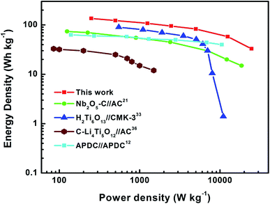 | ||
| Fig. 6 Ragone plots of the NbN/GNSs//APDC LIHC (this work). The energy and power density values are compared with those of other reported LIHCs. | ||
3 Conclusions
In summary, NbN/GNSs composite electrode has been successfully fabricated by combining 2D graphene nanosheets and 0D NbN nanoparticles through solution impregnation. The unique 0D/2D hybrid nanoarchitecture can generate a strong synergistic effect by fully utilizing the highly conductive graphene and the high-cyclical NbN. When used as a freestanding anode for Li-ion batteries, the nanocomposite shows excellent electrochemical properties including a high specific capacity of 450 mA h g−1 at 0.1 A g−1, a high-rate capacity of 100 mA h g−1 at a current density of 10 A g−1, and good cycling stability (10% decay in capacity after 10![[thin space (1/6-em)]](https://www.rsc.org/images/entities/char_2009.gif) 000 cycles). Furthermore, the NbN/GNSs//APDC LIHC shows an maximum energy density of 136 W h kg−1, and a power density of 25 kW kg−1. This special freestanding structure avoid the addition of binders, conductive agent and current collector, providing a reference for the design of next generation electrode materials.
000 cycles). Furthermore, the NbN/GNSs//APDC LIHC shows an maximum energy density of 136 W h kg−1, and a power density of 25 kW kg−1. This special freestanding structure avoid the addition of binders, conductive agent and current collector, providing a reference for the design of next generation electrode materials.
4 Experimental section
Niobium pentachloride was purchased from Sigma Aldrich Co. Ltd. Oxalic acid dihydrate was purchased from Sinopharm Co. and used without further purification. GO was synthesized from natural graphite by a modified Hummers method.38 NbN/GNSs composite papers were prepared by a simple three steps: vacuum filtration, solution impregnation and heat-treatment process.4.1 Vacuum filtration
50 mg GO powder was added into the 50 mL deionized water with ultrasonic treatment for 0.5 h (concentration: 1 mg mL−1), and the GO paper was prepared using PTFE membranes (0.22 μm in pore size) by vacuum filtration.4.2 Solution impregnation
0.218 g NbCl5 and 0.5 g oxalic acid dihydrate was injected into 20 mL deionized water with magnetic stirring, then, the GO papers were directly immersed in above solution. After 24 hours in the atmospheric environment, the wet GO papers were dredged up from this solution and then washed with deionized water to remove the remaining solvent. Subsequently, the GO papers were dried in vacuum at 80 °C.4.3 Heat-treatment process
The above production was put into a tube furnace and subjected to a nitridation treatment at 700 °C for 3 h in a flow of a mixture gas of NH3 and Ar (40 and 40 sccm). After cooled to room temperature spontaneously, the sample was taken out and the NbN/GNSs composite papers were obtained.4.4 Structural characterization
The morphology and microstructure of the samples were observed using SEM (FESEM, JSM 6701F, JEOL, Japan) and TEM (JEOL JEM-2100FEG). The XRD (PANalytical Empyrean) was performed at 40 kV and 20 mA using Cu-Kα radiation (λ = 0.15406 nm) to analyze the crystal structure of the samples. XPS (Perkin-Elmer PHI-5702 photoelectronic spectrometer) was used to analyze the surface elements of the samples. The conductivity of the samples were measured by using a conductivity meter with a four-point probe head (MCP-T610, Mitsubishi). Thermogravimetric analysis was performed using STA449F3 analyzer at a rate of 10 °C min−1 from room temperature to 800 °C in air flow with a rate of 100 mL min−1.4.5 Electrochemical measurements
The electrochemical properties were measured using coin-type (CR2032) half cells. The NbN/GNSs working electrodes were punched directly from the as-fabricated membranes, which were used as freestanding electrodes for cell assembly. The working electrodes were assembled in an argon filled glovebox with metal Li foils as the counter electrode, Celgard 2320 as the separators, and a solution of 1 M LiPF6 in ethylene carbonate (EC)/dimethyl carbonate (DMC)/diethyl carbonate (DEC) (1![[thin space (1/6-em)]](https://www.rsc.org/images/entities/char_2009.gif) :
:![[thin space (1/6-em)]](https://www.rsc.org/images/entities/char_2009.gif) 1
1![[thin space (1/6-em)]](https://www.rsc.org/images/entities/char_2009.gif) :
:![[thin space (1/6-em)]](https://www.rsc.org/images/entities/char_2009.gif) 1 by volume) as the electrolyte. To assemble a full battery, the NbN/GNSs papers (Φ = 12 mm) anode was coupled with a APDC cathode, which was prepared by coating conventional APDC nanoparticle slurry on an Al foil. For the LIHC assembly, the NbN/GNSs anode was first prelithiated by discharging the half cell to 0.001 V, and because the large irreversible capacity loss of the NbN/GNSs anode in the first cycle would lead to a severe capacity loss and degradation in a full cell. Electrochemical workstation (CHI660D, Shanghai, China) was employed to measure cyclic voltammetry (CV) curves in the range of 0.001–3 V at a rate of 0.5 mV s−1 and electrochemical impedance spectra (EIS) in the frequency range from 100 kHz to 50 mHz. The galvanostatic charge/discharge tests were carried out using a Land Battery Testing system (Land, China). To obtain optimized energy and power densities of the LIHC, the weight ratio of the active materials of the anode and cathode varied from 1
1 by volume) as the electrolyte. To assemble a full battery, the NbN/GNSs papers (Φ = 12 mm) anode was coupled with a APDC cathode, which was prepared by coating conventional APDC nanoparticle slurry on an Al foil. For the LIHC assembly, the NbN/GNSs anode was first prelithiated by discharging the half cell to 0.001 V, and because the large irreversible capacity loss of the NbN/GNSs anode in the first cycle would lead to a severe capacity loss and degradation in a full cell. Electrochemical workstation (CHI660D, Shanghai, China) was employed to measure cyclic voltammetry (CV) curves in the range of 0.001–3 V at a rate of 0.5 mV s−1 and electrochemical impedance spectra (EIS) in the frequency range from 100 kHz to 50 mHz. The galvanostatic charge/discharge tests were carried out using a Land Battery Testing system (Land, China). To obtain optimized energy and power densities of the LIHC, the weight ratio of the active materials of the anode and cathode varied from 1![[thin space (1/6-em)]](https://www.rsc.org/images/entities/char_2009.gif) :
:![[thin space (1/6-em)]](https://www.rsc.org/images/entities/char_2009.gif) 3 to 3
3 to 3![[thin space (1/6-em)]](https://www.rsc.org/images/entities/char_2009.gif) :
:![[thin space (1/6-em)]](https://www.rsc.org/images/entities/char_2009.gif) 1 in the potential range of 1.0–4 V. The specific capacitance is calculated according to the following equation based on the galvanostatic charge/discharge tests:
1 in the potential range of 1.0–4 V. The specific capacitance is calculated according to the following equation based on the galvanostatic charge/discharge tests:| C = I/[(dE/dt) × m] ≈ I/[(ΔE/Δt) × m] (F g−1) | (5) |
| E = 1/2 × C × (V22 − V12)/3.6 (W h kg−1) | (6) |
| P = E × 3600/t (W kg−1) | (7) |
Conflict of interest
The authors declare no competing financial interest.Acknowledgements
This work was supported by the National Natural Science Foundation of China (No. 51362018 and 21673263) and the Foundation for Innovation Groups of Basic Research in Gansu Province (No. 1606RJIA322).References
- P. Poizot, S. Laruelle, S. Grugeon, L. Dupont and J. M. Tarascon, Nature, 2000, 407, 496–499 CrossRef CAS PubMed.
- J. Jin, S.-Z. Huang, J. Shu, H.-E. Wang, Y. Li, Y. Yu, L.-H. Chen, B.-J. Wang and B.-L. Su, Nano Energy, 2015, 16, 339–349 CrossRef CAS.
- L.-Q. Mai, F. Yang, Y.-L. Zhao, X. Xu, L. Xu and Y.-Z. Luo, Nat. Commun., 2011, 2, 381 CrossRef PubMed.
- Y. Xu, Y. Tao, X. Zheng, H. Ma, J. Luo, F. Kang and Q. H. Yang, Adv. Mater., 2015, 27, 8082–8087 CrossRef CAS PubMed.
- N. Balke, S. Jesse, A. N. Morozovska, E. Eliseev, D. W. Chung, Y. Kim, L. Adamczyk, R. E. Garcia, N. Dudney and S. V. Kalinin, Nat. Nanotechnol., 2010, 5, 749–754 CrossRef CAS PubMed.
- Y. Zhai, Y. Dou, D. Zhao, P. F. Fulvio, R. T. Mayes and S. Dai, Adv. Mater., 2011, 23, 4828–4850 CrossRef CAS PubMed.
- Q. Wang, Z. H. Wen and J. H. Li, Adv. Funct. Mater., 2006, 16, 2141–2146 CrossRef CAS.
- A. D. Pasquier, I. Plitz, J. Gural, F. Badway and G. G. Amatucci, J. Power Sources, 2004, 136, 160–170 CrossRef.
- J. Han, L. L. Zhang, S. Lee, J. Oh, K.-S. Lee, J. R. Potts, J. Ji, X. Zhao, R. S. Ruoff and S. Park, ACS Nano, 2012, 7, 19–26 CrossRef PubMed.
- V. Aravindan, J. Gnanaraj, Y.-S. Lee and S. Madhavi, Chem. Rev., 2014, 114, 11619–11635 CrossRef CAS PubMed.
- Y. Ma, H. Chang, M. Zhang and Y. Chen, Adv. Mater., 2015, 27, 5296–5308 CrossRef CAS PubMed.
- R. Wang, J. Lang, P. Zhang, Z. Lin and X. Yan, Adv. Funct. Mater., 2015, 25, 2270–2278 CrossRef CAS.
- E. Lim, C. Jo, H. Kim, M.-H. Kim, Y. Mun, J. Chun, Y. Ye, J. Hwang, K.-S. Ha and K. C. Roh, ACS Nano, 2015, 9, 7497–7505 CrossRef CAS PubMed.
- X. Wang, C. Yan, J. Yan, A. Sumboja and P. S. Lee, Nano Energy, 2015, 11, 765–772 CrossRef CAS.
- K. Naoi, S. Ishimoto, J.-i. Miyamoto and W. Naoi, Energy Environ. Sci., 2012, 5, 9363–9373 CAS.
- L. Cheng, H.-J. Liu, J.-J. Zhang, H.-M. Xiong and Y.-Y. Xia, J. Electrochem. Soc., 2006, 153, A1472–A1477 CrossRef CAS.
- Z. Chen, V. Augustyn, J. Wen, Y. Zhang, M. Shen, B. Dunn and Y. Lu, Adv. Mater., 2011, 23, 791–795 CrossRef CAS PubMed.
- K. Naoi, Fuel Cells, 2010, 10, 825–833 CrossRef CAS.
- R. Yi, S. Chen, J. Song, M. L. Gordin, A. Manivannan and D. Wang, Adv. Funct. Mater., 2014, 24, 7433–7439 CrossRef CAS.
- H. Wang, Z. Xu, Z. Li, K. Cui, J. Ding, A. Kohandehghan, X. Tan, B. Zahiri, B. C. Olsen and C. M. Holt, Nano Lett., 2014, 14, 1987–1994 CrossRef CAS PubMed.
- E. Lim, H. Kim, C. Jo, J. Chun, K. Ku, S. Kim, H. I. Lee, I.-S. Nam, S. Yoon and K. Kang, ACS Nano, 2014, 8, 8968–8978 CrossRef CAS PubMed.
- Z. Chen, V. Augustyn, X. Jia, Q. Xiao, B. Dunn and Y. Lu, ACS Nano, 2012, 6, 4319–4327 CrossRef CAS PubMed.
- T. Brezesinski, J. Wang, J. Polleux, B. Dunn and S. H. Tolbert, J. Am. Chem. Soc., 2009, 131, 1802–1809 CrossRef CAS PubMed.
- T. Brezesinski, J. Wang, S. H. Tolbert and B. Dunn, Nat. Mater., 2010, 9, 146–151 CrossRef CAS PubMed.
- P. Han, W. Ma, S. Pang, Q. Kong, J. Yao, C. Bi and G. Cui, J. Am. Chem. Soc., 2013, 1, 5949–5954 CAS.
- P. Wang, R. Wang, J. Lang, X. Zhang, Z. Chen and X. Yan, J. Mater. Chem. A., 2016, 4, 9760–9766 CAS.
- J. Wang, J. Polleux, J. Lim and B. Dunn, J. Phys. Chem. C, 2007, 111, 14925–14931 CAS.
- B. Gao, X. Xiao, J. Su, X. Zhang, X. Peng, J. Fu and P. K. Chu, Appl. Surf. Sci., 2016, 383, 57–63 CrossRef CAS.
- G. Jouve, C. Séverac and S. Cantacuzene, Thin Solid Films, 1996, 287, 146–153 CrossRef CAS.
- X. Lu, M. Yu, T. Zhai, G. Wang, S. Xie, T. Liu, C. Liang, Y. Tong and Y. Li, Nano Lett., 2013, 13, 2628–2633 CrossRef CAS PubMed.
- V. Augustyn, J. Come, M. A. Lowe, J. W. Kim, P.-L. Taberna, S. H. Tolbert, H. D. Abruña, P. Simon and B. Dunn, Nat. Mater., 2013, 12, 518–522 CrossRef CAS PubMed.
- H. Kim, J. Hong, Y. U. Park, J. Kim, I. Hwang and K. Kang, Adv. Funct. Mater., 2015, 25, 534–541 CrossRef CAS.
- Y. Wang, Z. Hong, M. Wei and Y. Xia, Adv. Funct. Mater., 2012, 22, 5185–5193 CrossRef CAS.
- H. Lindström, S. Södergren, A. Solbrand, H. Rensmo, J. Hjelm, A. Hagfeldt and S.-E. Lindquist, J. Phys. Chem. B, 1997, 101, 7717–7722 CrossRef.
- G. Kim, C. Jo, W. Kim, J. Chun, S. Yoon, J. Lee and W. Choi, Energy Environ. Sci., 2013, 6, 2932–2938 CAS.
- R. Wang and X. Yan, Sci. Rep., 2014, 4, 3712 Search PubMed.
- H.-G. Jung, N. Venugopal, B. Scrosati and Y.-K. Sun, J. Power Sources, 2013, 221, 266–271 CrossRef CAS.
- L. Kong, C. Zhang, S. Zhang, J. Wang, R. Cai, C. Lv, W. Qiao, L. Ling and D. Long, J. Mater. Chem. A, 2014, 2, 17962–17970 CAS.
Footnote |
| † Electronic supplementary information (ESI) available. See DOI: 10.1039/c7ra01671a |
| This journal is © The Royal Society of Chemistry 2017 |

