DOI:
10.1039/C7RA01608E
(Paper)
RSC Adv., 2017,
7, 18821-18829
An investigation of mass transfer-reaction kinetics of NO absorption by wet scrubbing using an electrolyzed seawater solution
Received
8th February 2017
, Accepted 22nd March 2017
First published on 28th March 2017
Abstract
The mass transfer-reaction kinetics of NO absorption by wet scrubbing using electrolyzed seawater was studied in a bench-scale bubbling reactor. The effects of active chlorine concentration, solution pH, absorbent temperature, NO and SO2 inlet concentrations on NO absorption rate were investigated. The results showed that the NO absorption rate significantly increased from 0.41 × 10⁻⁵ to 1.91 × 10⁻⁵ mol m−2 s−1 with the active chlorine concentration increasing from 500 to 3100 mg L−1 [Cl2]. The NO absorption rate greatly increased from 0.25 × 10⁻⁵ to 1.58 × 10⁻⁵ mol m−2 s−1 with NO concentration increasing from 250 to 1250 ppm. When SO2 inlet concentration increased from 250 to 1250 ppm, the NO absorption rate slightly increased from 1.09 × 10⁻⁵ to 1.17 × 10⁻⁵ mol m−2 s−1. When the solution pH was in the range of 4–6, the NO absorption rate was about 1.5 × 10⁻⁵ mol m−2 s−1. The change of the NO absorption rate was insignificant with the absorbent temperature increasing from 20 to 50 °C. The influential mechanism of the NO absorption rate was also discussed preliminarily. Furthermore, the NO absorption process by electrolyzed seawater was pseudo-first-order reaction with respect to NO concentration. A simplified equation of NO absorption rate was also obtained. The comparison results indicated that the calculated values agreed well with the experimental values.
1. Introduction
The emission of NOx from stationary and mobile sources is a major environmental concern due to their detrimental effects (e.g., acid rain, photochemical smog, tropospheric ozone layer depletion and even global warming) on human health and ecosystems.1 With the implementation of stringent regulations on NOx emission, there are eager demands for developing new technologies and improving the currently used methods for NOx removal from exhaust gas.
Apart from the combustion control methods aimed at reducing the formation of NOx during the combustion process, there are a lot of post-combustion treatment technologies that can be further divided into two categories: oxidation and reduction methods. The reduction methods mainly include selective catalytic reduction (SCR) and selective non-catalytic reduction (SNCR).2,3 SCR can reduce NOx into N2 in the presence of catalysts and reductants, and its NOx removal efficiency is very high. However, it usually requires a high catalyst activation temperature, and a large installation space. SCR system is very complex, and its capital and operating cost are very high. For SNCR, a very high reaction temperature of 850–1100 °C is required to facilitate the reduction reaction between NOx and reductants. Moreover, an elaborate temperature control is critical for avoiding ammonia slip.
The oxidation methods for NOx abatement aim at oxidizing NO into higher order nitrogen oxides that can be easily removed by chemical absorption. Recently, numerous chemical oxidants, such as non-thermal plasma,4,5 O3,6 KMnO4,7 H2O2,8–11 Na2S2O8,12,13 oxone,14,15 NaClO2,16–18 ClO2,19 Ca(ClO)2,20 and NaClO,21,22 have been investigated in order to improve the NO removal efficiency of the oxidation methods. Among these oxidants, NaClO are very attractive for practical applications because it has some obvious advantages such as low cost, strong oxidability, and easy storage and transportation. During the past few decades, the denitration performance and the reaction mechanism of NO removal by NaClO oxidation have been explored in detail.23–26 Guo R. T. et al. studied the absorption kinetics of NO into weakly acidic NaClO solution in a stirred tank reactor.27 Deshwal B. R. et al. studied the reaction kinetics of oxidative absorption of NO into NaClO solution in a bubbling reactor.28 Recently, Sukheon A. N. et al. proposed the application of electrolyzed seawater to remove NO from marine exhaust gas, which was of great potential in industrial applications such as onshore power plants and ocean-going vessels.29
It is well known that, the oxidative components in electrolyzed seawater are active chlorine species, which are the same with commercial NaClO solution. Yang S. L. et al. conducted the experiments of seawater electrolysis in an undivided cell, and studied the NOx removal by wet scrubbing electro-generated chlorine in a spray reactor.30 However, the mass transfer-reaction kinetics of NO removal by electrolyzed seawater has not been reported yet. The purpose of this study is to investigate the mass transfer-reaction kinetics of NO removal by wet scrubbing using electrolyzed seawater process. The effects of several operating parameters (e.g., such as active chlorine concentration, solution pH, absorbent temperature, NO and SO2 inlet concentrations) on NO absorption rate are evaluated. A simple NO absorption rate equation is also established. The results will provide a theoretical basis for the numerical simulation of NO absorption by electrolyzed seawater process, and the industrial application of this technology.
2. Materials and methods
2.1 Experimental apparatus
Fig. 1 shows the schematic diagram of the experimental system, including simulated flue gas unit, bubble column reactor and flue gas analysis system. The bubble column reactor consists of constant temperature water bath, bubble column, thermometer and gas distributor. The height and inner diameter of the bubble column are 600 and 50 mm, respectively. The gas distributor (ISO 4793 P4, pore size 10–15 μm) used to uniformly distribute the simulated flue gas, is located at the bottom of the bubble column. The constant temperature water bath (Julabo F34-ED Refrigerated/Heating Circulator, Germany) is used to adjust the absorbent temperature to the desired values. A gas analyzer (MRU MGA5, Germany) is used to measure the concentrations of multi pollutants such as NO, NO2, and SO2. In order to effectively remove moisture from the flue gas before it enters the gas analyzer, an additional electric condenser is used as a drier.
 |
| | Fig. 1 Schematic diagram of the experimental system. | |
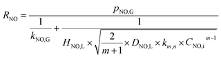
2.2 Experimental procedures
The simulated flue gas was prepared continuously by mixing three kinds of gases, N2 pure gas (99.999%), NO span gas (10.04% NO with N2 as balance gas), and SO2 span gas (10.1% SO2 with N2 as balance gas). The flow rate of each gas from the separate air bottles was metered through mass flow controllers (MFCs, Beijing Sevenstar Electronics Co., Ltd). The inlet concentrations of gas pollutants were measured using the gas analyzer through gas bypass B.
The electro-generated chlorine was produced by artificial seawater electrolysis in an undivided cell as described previously.30 The artificial seawater (pH 8.2, salinity 23.3 ppt) was prepared according to the ASTM D1141 standard.1 To reduce the deterioration of electro-generated chlorine during the experiments, the electrolyte was stored in a water bath (20 °C) and was shielded from light. For each gas absorption experiment, the absorbent solution was prepared by diluting the electrolyzed seawater with fresh artificial seawater. The initial pH values of bubbling solution were adjusted to the desired values by adding HCl solution (1 mol L−1) or NaOH solution (1 mol L−1), and were measured by a pH meter (Mettler-Toledo S210, Switzerland). The active chlorine concentrations (ACCs) in absorbent solution were determined by N,N-diethyl-p-phenylenediamine (DPD) colorimetric method (ASTM 4500 G), using a spectrophotometer (Shimadzu UV1800, Japan) at 515 nm. The temperature of bubbling liquid was adjusted to the set value by the water bath. After the inlet concentrations of gas pollutants and solution temperature reached the required values and kept stable, the simulated flue gas was introduced into the bubble column reactor by switching the gas valves of V1 and V2. The gas–liquid reaction occurred under atmospheric pressure. The outlet concentrations of gas pollutants were monitored using the gas analyzer at 10 s interval. Each experiment was replicated for 3 times and the duration of each test was kept for 15 min. For each experiment, the average concentrations of targeted pollutants measured for the last 10 min were used as outlet concentrations of pollutants.
To verify NO absorption by wet scrubbing using electrolyzed seawater, the anions of NO3− and NO2− in the scrubbing solution were measured via ion chromatography (Dionex ICS-1500).
2.3 NO absorption rate
According to the material balance and the ideal gas equation, the NO absorption rate (RNO, mol m−2 s−1) can be calculated using the following equation:| |
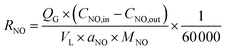 | (1) |
where QG is the volumetric flue gas flow rate, L min−1; CNO,in and CNO,out are the inlet and outlet concentrations of NO, respectively, mg m−3; VL is the volume of solution, L; aNO is the interfacial area between gas and liquid per unit volume of the system, m2 m−3; MNO is the molecular weight of NO, 30 g mol−1.
2.4 Physical parameters
The solubility coefficients of NO in liquid phase (HNO,L) are calculated using the solubility coefficients of NO in water (HNO,w) and the Van Krevelen & Hoftizer empirical equation. The diffusion coefficients of NO in liquid phase (DNO,L) are calculated using the diffusion coefficients of NO in water (DNO,w) and the Wilke–Chang empirical equation. The HNO,w and DNO,w can be obtained by consulting references.14,31 The diffusion coefficients of NO in gas phase (DNO,G) are estimated by the Chapman–Enskog semi-empirical equation.32
2.5 Mass transfer parameters
It is difficult to directly measure the mass transfer coefficients of NO in gas–liquid reaction. For instead, the mass transfer parameters of the CO2 absorption system can be determined. Then they can be used to calculate the mass transfer coefficients of NO in gas–liquid reaction according to the following equations.| |
 | (2) |
| |
 | (3) |
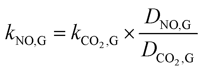
where kNO,L and kCO2,L are the liquid phase mass transfer coefficients of NO and CO2, respectively, m s−1; DNO,L and DCO2,L are the liquid phase diffusion coefficients of NO and CO2, respectively, m2 s−1; kNO,G and kCO2,G are the gas phase mass transfer coefficients of NO and CO2, respectively, mol m−2 s−1 Pa−1; DNO,G and DCO2,G are the gas phase diffusion coefficients of NO and CO2, respectively, m2 s−1; aNO and aCO2 are the gas–liquid specific interfacial areas of NO and CO2, respectively, m2 m−3.
The gas–liquid mass transfer parameters (kCO2,L and aCO2) of a CO2 absorption system are determined by the classical chemical methods, including the absorption of CO2 in NaClO–Na2CO2/NaHCO3 solution and the absorption of CO2 in NaOH solution, and Danckwerts plot theory. Then kNO,L and aNO are obtained as follows:
| |
 | (5) |
| |
 | (6) |
where
T is the gas temperature, °C. Similarly, the gas–liquid mass transfer parameter (
kNO,G) of NO absorption can be obtained by the following relation:
| |
 | (7) |
The physical and mass transfer parameters of our NO absorption system are summarized in Table 1. The related parameters for NO absorption are under conditions of solution temperature 20 °C and gas flow rate of 1.25 L min−1.
Table 1 Physical and mass transfer parameters of the NO absorption system
| HNO,L × 107 (mol Pa−1 L−1) |
DNO,L × 109 (m−2 s−1) |
kNO,L × 105 (m s−1) |
kNO,G × 107 (mol m−2 s−1 Pa−1) |
aNO × 10 (m2 m−3) |
| 1.98 |
1.97 |
2.04 |
5.52 |
4.12 |
3. Results and discussion
3.1 Effects of process parameters on NO absorption rate
3.1.1 Effects of active chlorine concentration. The effects of active chlorine concentration in electrolyzed seawater solution on the absorption rate of NO were evaluated, and the results are shown in Fig. 2. When the active chlorine concentration was increased from 500 to 3100 mg L−1 [Cl2], the NO absorption rate significantly increased from 0.41 × 10⁻⁵ to 1.91 × 10⁻⁵ mol m−2 s−1. This can be explained by the theory of chemical reaction kinetics. The increase of reactant concentration will increase the reaction rate between active chlorine species and NO, thereby increasing the NO absorption rate. But it seems that the increase of the NO absorption rate becomes a little slower with the increasing of active chlorine concentration. That is because the NO absorption reaction is a gas–liquid heterogeneous reaction, which is simultaneously controlled by chemical reaction and mass transfer. So it is possible that the increase of NO absorption rate will become insignificant when the active chlorine concentration is relatively high.
 |
| | Fig. 2 Effects of active chlorine concentration on NO absorption rate (conditions: NO inlet concentration, 1000 ppm; SO2 inlet concentration, 0 ppm; solution pH, 7; absorbent temperature, 20 °C). | |
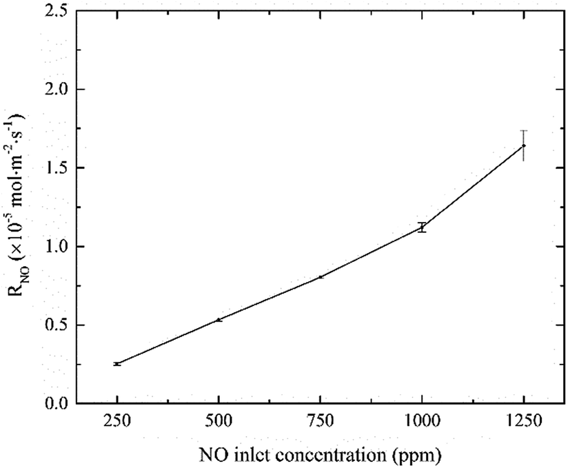
3.1.2 Effects of NO inlet concentration. The effects of NO inlet concentration on NO absorption rate were studied, and the results are shown in Fig. 3. It can be seen that, NO absorption rate greatly increased from 0.25 × 10⁻⁵ to 1.58 × 10⁻⁵ mol m−2 s−1 with NO concentration increasing from 250 to 1250 ppm. According to the two-film theory, an increase in NO concentration will increase the mass transfer driving force of NO in the gas-phase side, thereby increasing the reaction rate of active chlorine species with NO at the gas–liquid interface. That is the main reason for the increasing of NO absorption rate. In addition, the curve showed almost linear relationship between the NO absorption rate and the NO inlet concentration as the other parameters remained constant. The results indicated that NO absorption by active chlorine in electrolyzed seawater was a first-order reaction with respect to NO concentration.
 |
| | Fig. 3 Effects of NO inlet concentration on NO absorption rate (conditions: active chlorine concentration, 1500 mg L−1 [Cl2]; SO2 inlet concentration, 0 ppm; solution pH, 7; absorbent temperature, 20 °C). | |
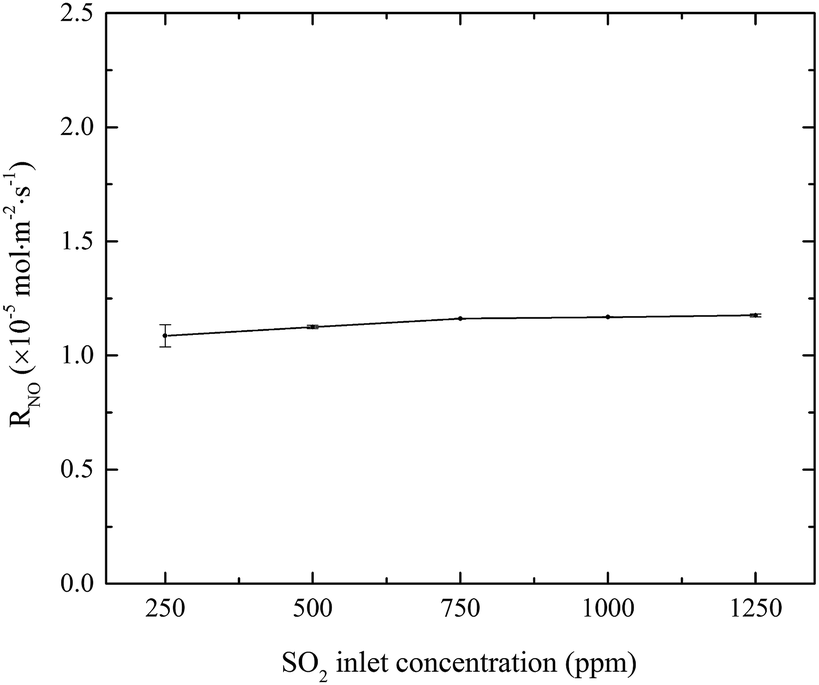
3.1.3 Effects of SO2 inlet concentration. The effects of SO2 concentration on NO absorption rate were investigated, and the results are shown in Fig. 4. When SO2 inlet concentration increased from 250 to 1250 ppm, SO2 was removed completely and NO absorption rate slightly increased from 1.07 × 10⁻⁵ to 1.17 × 10⁻⁵ mol m−2 s−1. Since SO2 is very soluble in water, it will be quickly absorbed and hydrolyzed into HSO3− and SO32− by eqn (8)–(10). These hydrolysis products will react with active chlorine in the electrolyzed seawater, competing with NO.22 At the same time, the absorption of SO2 will lead to the decrease of solution pH. It is known that the fractional compositions of active chlorine species in NaClO solution greatly changed with the solution pH. With the decrease of solution pH from 7 to a lower value (>5.3), the fractional concentration of HClO will increase.20 Since HClO plays the key role in oxidizing NO into NO2, so the generation of H+ might be favorable to increasing the NO absorption rate for electro-chlorine system.23| | |
H2SO3 ↔ HSO3− + H+ ↔ SO32− + 2H+
| (10) |
| | |
HSO3− + HClO/ClO− → SO4− + H+ + Cl−/H+ + Cl−
| (11) |
| | |
SO32− + HClO/ClO− → SO4− + Cl−/H+ + Cl−
| (12) |
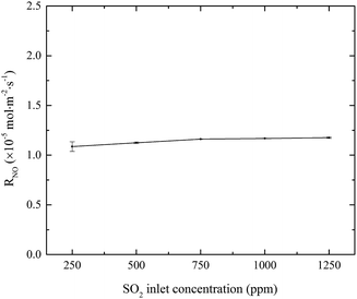 |
| | Fig. 4 Effects of SO2 concentration on NO absorption rate (conditions: active chlorine concentration, 1500 mg L−1 [Cl2]; NO inlet concentration, 1000 ppm; solution pH, 7; absorbent temperature, 20 °C). | |
Some previous studies also showed that the presence of low to moderate concentrations of SO2 (990–2520 ppm) could enhance NO removal.14,19,33–39 These could be due to the fact that, in the presence of SO2, there are also important side reactions between the bisulfite ion (HSO3−) and NO2(l), nitrite (NO2−) or nitrous acid (HNO2) by eqn (13)–(15) to produce N–S intermediates such as hydroxylamine disulfonate (HON(SO3)22−) and nitrososulfonic acid (ONSO3− or NSS), which have been identified by a number of investigators.14,33,40–48
| | |
2NO2(l) + HSO3− + H2O → 2NO2− + SO42− + 3H+
| (13) |
| | |
NO2− + H+ + 2HSO3− ↔ HON(SO3)22− + H2O
| (14) |
| | |
NO2− + H+ + HSO3− → ONSO3− + H2O
| (15) |
Which of these reactions predominates will depend on the concentrations of the components, the temperature, and the pH of the solution.41 Furthermore, the stoichiometry and the rates for the reactions between S(IV) ions (HSO3− and SO32−) and NO2 in aqueous solutions have been studied by many researchers.40–42,49,50 The reaction of NO2(l) with sulphite (SO32−) is considered to be significantly more rapid than with bisulfite (HSO3−) with an overall stoichiometry:49–51
| | |
2NO2(l) + SO3− + H2O → 2NO2− + SO42− + 2H+
| (16) |
But Littlejohn et al. thought that the main loss mechanism for nitrite ion was the reaction with bisulfite to form N–S compounds.40
3.1.4 Effects of solution pH. The effects of solution initial pH value on NO absorption rate were evaluated, and the results are shown in Fig. 5. As the fractional compositions of active chlorine species in electro-chlorine system greatly depended on the solution pH, the NO absorption rate changed obviously with the solution pH.20 When solution pH increased from 3 to 4, the fractional concentration of HClO increased largely, resulting in the increase of NO absorption rate. When solution pH was in the range of 4–6, the majority active chlorine species existed in the form of HClO, which could oxidize NO into NO2 effectively. The result indicated that the reaction rate of NO with HClO was independent to the solution pH when the pH was in the range of 4–6. It was possible that the HClO concentration was relatively excessive at that moment. However, when solution pH decreased from 6 to 10, NO absorption rate decreased largely from 1.45 × 10⁻⁵ to 0.02 × 10⁻⁵ mol m−2 s−1. It was mainly ascribed to the decrease of the fractional concentration of HClO in the electro-chlorine system. In alkaline medium, the active chlorine species mainly existed in the form of ClO−. Although the oxidability of ClO− was high, there was no evidence that ClO− could oxidize NO into NO2 effectively.23,24
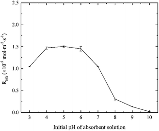 |
| | Fig. 5 Effects of solution pH value on NO absorption rate (conditions: active chlorine concentration, 1500 mg L−1 [Cl2]; NO inlet concentration, 1000 ppm; SO2 inlet concentration, 0 ppm; absorbent temperature, 20 °C). | |
3.1.5 Effects of absorbent temperature. The effects of absorbent temperature on NO absorption rate were studied, and the results are shown in Fig. 6. It can be seen that, the change of NO absorption rate was insignificant with the absorbent temperature increasing from 20 to 50 °C. Generally, according to theories of gas–liquid mass transfer and chemical reaction kinetics, the increase of absorbent temperature will increase the mass transfer driving force of NO and active chlorine species in the gas–liquid two phases. Thus it is possible to obtain an increased NO absorption rate. But it was worthy to note that, the increase of absorbent temperature might decrease the solubility of NOx in water solution. Thus the absorbent temperature imposed little effect on NO absorption rate in this experiment.
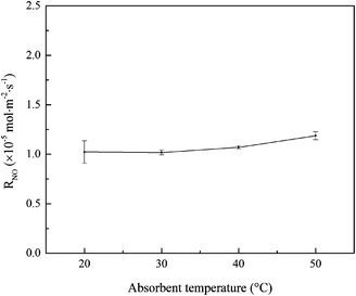 |
| | Fig. 6 Effects of absorbent temperature on NO absorption rate (conditions: active chlorine concentration, 1500 mg L−1 [Cl2]; NO inlet concentration, 1000 ppm; SO2 inlet concentration, 0 ppm; solution pH, 7). | |
3.1.6 Analysis of reaction products. To verify the NO absorption by wet scrubbing using electrolyzed seawater, the anions of NO3− and NO2− in the scrubbing solution were measured via IC. The related experimental conditions were: active chlorine concentration, 1500 mg L−1 [Cl2]; NO inlet concentration, 1000 ppm; SO2 inlet concentration, 0 ppm; initial solution pH, 7; absorbent temperature, 20 °C. The bubbling process lasted for 30 min, and the sample solutions was withdrawn from the bubbling reactor every 10 min. As Cl− concentration in electrolyzed seawater was too high for IC measurement, the sample solutions was diluted 10 times, and then filtered by Ag cartridge and H cartridge, successively, in order to remove the majority of chloride ions. For each sample solution, IC tests were replicated for 3 times. The results showed that there was no NO2− in the sample solutions. It indicated that most of the absorbed NO was turned into NO3−. The measured values and calculated values of NO3− were listed in Table 2. It was thought that, the errors between the measured values and calculated ones mainly resulted from the sampling and processing procedure. With the increase of bubbling duration, the NO3− concentration increased accordingly. Thus the results reflected the NO absorption during the wet scrubbing using electrolyzed seawater properly.
Table 2 The measured values and calculated values of NO3− concentrations in the sample solutions
| Duration (min) |
Measured values (mg L−1) |
Calculated values (mg L−1) |
Errors (%) |
| 10 |
18.04 |
22.30 |
19.10 |
| 20 |
35.43 |
45.72 |
22.51 |
| 30 |
66.75 |
70.26 |
5.00 |
3.2 Kinetics of NO absorption
3.2.1 Theoretical fundamentals. As mentioned above, the effective components for NO absorption in electro-chlorine system was HClO, according to the previous studies of NO removal by wet scrubbing using sodium hypochlorite (NaClO) solution.21,24,30,52 The reaction rate of NO with ClO− was much slower than that of NO with HClO,23 so the oxidation and absorption of NO in electro-chlorine system mainly referred to the reactions between NO and HClO.| | |
2NO + 3HOCl + H2O → 2HNO3 + 3HCl
| (17) |
According to the chemical reaction kinetic theory,31,53 the NO removal by electro-generated chlorine can be regarded as a partial j-order reaction for H2O, a partial m-order reaction for NO and a partial n-order reaction for HOCl, respectively. The chemical reaction rate equation can be expressed as the following equation:
| | |
RNO = kj,m,n × CH2Oi × CNO,im × CHOCln
| (18) |
where
kj,m,n is (
j +
m +
n) order rate constant for the overall reaction
(17);
CH2O is H
2O concentration in liquid phase, mol L
−1;
CNO,i is the NO concentration at gas–liquid interface, mol L
−1;
CHOCl is the electro-generated chlorine concentration in bulk liquid phase, mol L
−1;
j is partial reaction order for H
2O;
m is partial reaction order for NO;
n is partial reaction order for HOCl.
As H2O is the solvent of the bubbling liquid, CH2O is considered to be infinite, so it could be regarded as a constant compared to CNO,i and CHOCl. Thus the chemical reaction of NO absorption can be regarded as a pseudo-m-order reaction for NO and a pseudo-n-order reaction for HOCl. The NO absorption rate equation can be further simplified to the following equation:
| | |
RNO = km,n × CNO,im × CHOCln
| (19) |
where
km,n =
kj,m,n ×
CH2O is pseudo-(
m +
n)-order rate constant for NO and HOCl.
According to two-film theory, the NO absorption rate can be described as:54
| | |
RNO = kNO,G × (pNO,G − pNO,i) = E × kNO,L × (CNO,i − CNO,L)
| (20) |
where
RNO is the NO absorption rate, mol m
−2 s
−1;
pNO,G is the partial pressure of NO in the bulk gas, Pa;
pNO,i is the partial pressure of NO at gas–liquid interface, Pa;
CNO,L is the NO concentration in the bulk liquid phase, mol L
−1;
E is the chemical reaction enhancement factor.
According to the Henry law, the equilibrium relationship at the gas–liquid interface can be obtained as:
| | |
CNO,i = HNO,L × pNO,i
| (21) |
where
HNO,L is solubility coefficient of NO in solution, mol L
−1 Pa
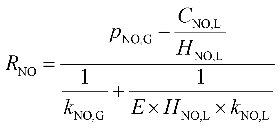
−1. Then the NO absorption rate equation can be rearranged to the following
eqn (22) through solving the above
eqn (20) and
(21).
| |
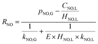 | (22) |
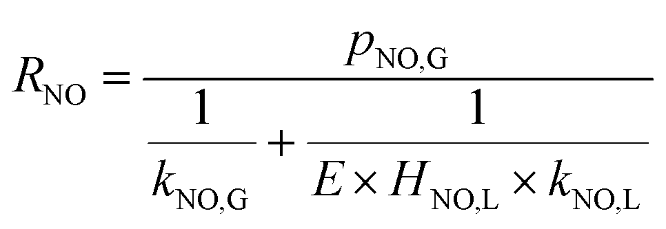
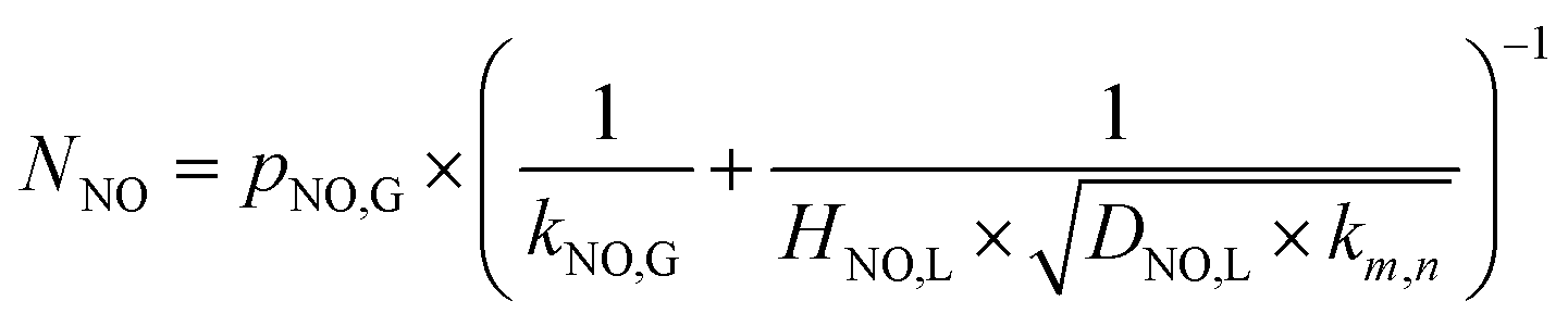
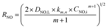
According to the results of Guo R. T. et al.,27 the NO absorption process was a first-order fast reaction with respect to both NO and NaClO concentrations when the experiments on NO absorption kinetics were performed with weakly acidic NaClO solution. In the present study, it was firstly supposed that the NO removal by electro-generated chlorine was a fast reaction. This hypothesis would be validated in the following section. For a fast reaction, NO was completely removed before it entered into the bulk liquid phase, according to the two-film theory, so that CNO,L = 0. Therefore, the NO absorption rate eqn (22) can be further simplified to the following equation:
| |
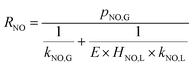 | (23) |
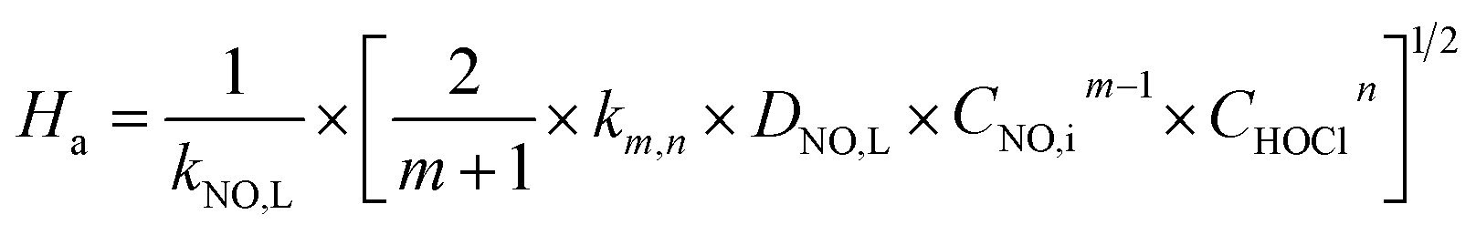
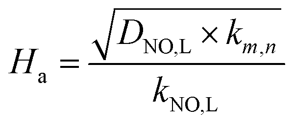
Furthermore, for an irreversible pseudo-m-order reaction, the chemical reaction enhancement factor E can be approximated as:
| |
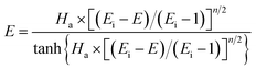 | (24) |
where
Ei is the enhancement factor for the instantaneous reaction;
Ha is defined as the ratio of the maximum possible conversion in the film to the maximum diffusion transport through the film, which is given by:
| |
 | (25) |
When the NO absorption process is a fast reaction, Ha > 3.0, and there is E = Ha. Thus, the NO absorption rate eqn (23) can be further expressed as follows:
| |
 | (26) |
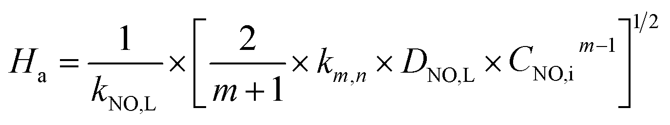
When active chlorine concentration of 1500 mg L−1 [Cl2] and NO inlet concentration of 1000 ppm were taken into consideration, the molar concentration of active chlorine in electro-chlorine system (2.1 × 10⁻² mol L−1) was about 495 times higher than that of NO (4.24 × 10⁻⁵ mol L−1). Thus the active chlorine concentration in electro-chlorine system could be regarded as a constant parameter during each experiment run. So the eqn (25) and (26) could be further simplified as follows:
| |
 | (27) |
| |
 | (28) |
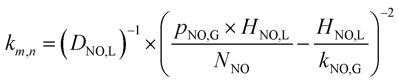
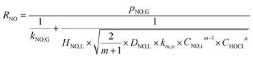
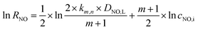
3.2.2 Determination of reaction order for NO. The kinetics of NO concentration could be obtained from the transformation of eqn (28):| |
 | (29) |
NO interface concentration could be expressed as eqn (30) by combining the eqn (20) and (21):
| |
 | (30) |
Through solving the above eqn (29) and (30), NO absorption rate could be expressed as the following equation:
| |
 | (31) |
The following eqn (32) could be obtained by taking a logarithm on both sides of the eqn (31):
| |
 | (32) |
The relationship between ln(RNO) and ln(CNO,i) is presented in Fig. 7. The slope of the fitted line was 1.15. That was (m + 1)/2 = 1.15. Therefore, the reaction order of NO concentration m was 1.3, taking the integer m = 1. It indicated that the NO absorption by wet scrubbing electrolyzed seawater was a pseudo-first-order reaction with respect to the NO concentration. Thus the equation of NO absorption rate could be expressed as follows:
| |
 | (33) |
 |
| | Fig. 7 Plot of log(RNO) versus log(CNO,i) (conditions: active chlorine concentration, 1500 mg L−1 [Cl2]; NO inlet concentration, 1000 ppm; solution pH, 7; gas flow, 1.25 L min−1; absorbent temperature, 20 °C). | |
3.2.3 Reaction rate constant and validation of NO absorption rate equations. The (m + n) order rate constant (km,n) for the reaction (17) could be calculated by eqn (1) and (33), and the results are summarized in Table 3. The related experimental conditions were SO2 inlet concentration of 0 ppm; solution pH of 7; and absorbent temperature of 20 °C.| |
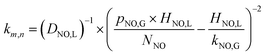 | (34) |
Table 3 Kinetic parameters of NO absorption by wet scrubbing using electrolyzed seawater
| Parameters |
RNOa (10−5 mol m−2 s−1) |
RNOb (10−5 mol m−2 s−1) |
Error (%) |
km,n (10−3 s−1) |
Ha |
| Experimental values. Calculation values. |
| CNO ppm (1500 mg L−1 [Cl2]) |
250 |
0.25 |
0.27 |
7.4% |
0.32 |
3.9 |
| 500 |
0.53 |
0.52 |
−1.9% |
0.36 |
4.2 |
| 750 |
0.80 |
0.81 |
1.2% |
0.37 |
4.2 |
| 1000 |
0.11 |
1.14 |
2.6% |
0.43 |
4.6 |
| 1250 |
1.58 |
1.54 |
−2.6% |
0.56 |
5.2 |
| CNO ppm (2500 mg L−1 [Cl2]) |
250 |
0.42 |
0.41 |
−2.4% |
1.20 |
7.6 |
| 500 |
0.77 |
0.81 |
4.9% |
0.94 |
6.8 |
| 750 |
1.22 |
1.21 |
−0.8% |
1.11 |
7.3 |
| 1000 |
1.68 |
1.66 |
−1.2% |
1.21 |
7.6 |
| 1250 |
2.07 |
2.12 |
2.4% |
1.15 |
7.5 |
| CACC mg L−1 [Cl2] (NO, 1000 ppm) |
500 |
0.40 |
0.42 |
4.8% |
0.04 |
1.4 |
| 1000 |
0.83 |
0.82 |
−1.2% |
0.20 |
3.1 |
| 1500 |
1.17 |
1.14 |
−2.6% |
0.46 |
4.7 |
| 2000 |
1.45 |
1.42 |
−2.1% |
0.80 |
6.2 |
| 2500 |
1.68 |
1.66 |
−1.2% |
1.21 |
7.6 |
| 3100 |
1.91 |
1.90 |
−0.5% |
1.77 |
9.3 |
According to the two-film theory, for a pseudo-first-order reaction with respect to NO concentration, the expression (21) of Ha could be further simplified to the following equation:
| |
 | (35) |
where
DNO,L and
kNO,L can be obtained in
Table 1. From
Table 3, it can be seen that, all of the
Ha are greater than 3.0. It indicates that the NO absorption by wet scrubbing using electrolyzed seawater is a fast chemical reaction under the present conditions.
In order to facilitate the calculation of NO absorption rate in the future industrial applications, the (m + n) order rate constant (km,n) for the reaction (17) are fitted into the following empirical eqn (36) with NO concentration, and active chlorine concentration.
| km,n = −4.32 × 10³ − 2.56 × 10 × CNO + 5.16 × CACC + 2.75 × 10⁻² × CNO2 + 1.68 × 10⁻² × CACC2 |
The calculated values and the experimental values of NO absorption rates under different experimental conditions were compared, and the results are also shown in Table 3. It can be seen that under all the experimental conditions, the calculated values are in good agreement with the experimental values. The average error is 2.49% and the maximal error is less than 7.4% between the calculated values and the experimental values. It is acceptable in the study of the gas–liquid reaction. Thus NO absorption rate equation can be used to simulate the absorption process of NO absorption by wet scrubbing using electrolyzed seawater process, and offers some meaningful guidance for the design and amplification of the reactor to some extent.
4. Conclusions
The mass transfer-reaction kinetics of NO absorption by electrolyzed seawater was studied in a bubbling reactor. The effects of active chlorine concentration, solution pH, absorbent temperature, NO and SO2 inlet concentrations on NO absorption rate were investigated. The results showed that, NO absorption rate significantly increased with the increase of active chlorine concentration and NO inlet concentration. NO absorption rate slightly increased with the increase of SO2 inlet concentration. Since the fractional compositions of active chlorine species in electrolyzed seawater greatly depended on the solution pH, NO absorption rate obviously changed with the solution pH. When solution pH was at 7, NO absorption rate was 1.06 × 10⁻⁵ mol m−2 s−1. The NO absorption process by electrolyzed seawater was pseudo-first-order reaction with respect to NO concentration. It was a fast chemical reaction in the present study. A simplified equation of NO absorption rate was established, and the comparison results indicated that the calculated values agreed well with the experimental values.
Acknowledgements
This paper was supported by the National Natural Science Foundation of China (No. 51402033 and 51479020), the Science and Technology Plan Project of China's Ministry of Transport (2015328225150) and the Fundamental Research Funds for the Central Universities (3132016018), and the Scientific Research Fund of Liaoning Provincial Education Department of China (No. L2014198). Dr Kaiying Liu was appreciated for the help of IC measurement.
Notes and references
- Z. T. Han, S. L. Yang, D. K. Zheng, X. X. Pan and Z. J. Yan, SpringerPlus, 2016, 5, 751 CrossRef PubMed.
- G. Busca, L. Lietti, G. Ramis and F. Berti, Appl. Catal., B, 1998, 18, 1–36 CrossRef CAS.
- M. T. Javed, N. Irfan and B. M. Gibbs, J. Environ. Manage., 2007, 83, 251–289 CrossRef CAS PubMed.
- S. L. Ding, Q. Yu, Y. Z. Zhang, Y. Liu, C. X. Xie and G. Yu, J. Adv. Oxid. Technol., 2015, 18, 114–122 CAS.
- D. Y. Xie, Y. Sun, T. Zhu and L. Ding, Energy Fuels, 2016, 30, 5071–5076 CrossRef CAS.
- S. P. Guo, L. N. Lv, J. Zhang, X. Chen, M. Tong, W. Z. Kang, Y. B. Zhou and J. Lu, Chem. Ind. Chem. Eng. Q., 2015, 21, 305–310 CrossRef CAS.
- P. Fang, C. P. Cen, X. M. Wang, Z. J. Tang, Z. X. Tang and D. S. Chen, Fuel Process. Technol., 2013, 106, 645–653 CrossRef CAS.
- Y. Zhao, R. L. Hao, P. Zhang and S. H. Zhou, Energy Fuels, 2014, 28, 6502–6510 CrossRef CAS.
- Y. X. Liu, J. Zhang, C. D. Sheng, Y. C. Zhang and L. Zhao, Energy Fuels, 2010, 24, 4925–4930 CrossRef CAS.
- Y. X. Liu, J. F. Pan, A. K. Tang and Q. Wang, Fuel, 2013, 108, 254–260 CrossRef CAS.
- Y. X. Liu, J. Zhang and C. D. Sheng, Energy Fuels, 2011, 25, 1547–1552 CrossRef CAS.
- Z. P. Wang and Z. W. Wang, Ind. Eng. Chem. Res., 2015, 54, 9905–9912 CrossRef CAS.
- N. E. Khan and Y. G. Adewuyi, Ind. Eng. Chem. Res., 2010, 49, 8749–8760 CrossRef CAS.
- Y. G. Adewuyi and S. O. Owusu, Ind. Eng. Chem. Res., 2003, 42, 4084–4100 CrossRef CAS.
- Y. G. Adewuyi and S. O. Owusu, J. Phys. Chem. A, 2006, 110, 11098–11107 CrossRef CAS PubMed.
- N. D. Hutson and R. Krzyzynska, Ind. Eng. Chem. Res., 2008, 47, 5825–5831 CrossRef CAS.
- H. K. Lee, B. R. Deshwal and K. S. Yoo, Korean J. Chem. Eng., 2005, 22, 208–213 CrossRef CAS.
- Y. G. Adewuyi, X. He, H. Shaw and W. Lolertpihop, Chem. Eng. Commun., 1999, 174, 21–51 CrossRef CAS.
- B. R. Deshwal, D. S. Jin, S. H. Lee, S. H. Moon, J. H. Jung and H. K. Lee, J. Hazard. Mater., 2008, 150, 649–655 CrossRef CAS PubMed.
- Y. Zhou, C. T. Li, C. Z. Fan, M. F. Fu, L. Tao, M. G. Yu and M. Y. Zhang, Environ. Prog. Sustainable Energy, 2015, 34, 1586–1595 CrossRef CAS.
- M. K. Mondal and V. R. Chelluboyana, Chem. Eng. J., 2013, 217, 48–53 CrossRef CAS.
- Z. T. Han, S. L. Yang, X. X. Pan, D. S. Zhao, J. Q. Yu, Y. T. Zhou, P. F. Xia, D. K. Zheng, Y. H. Song and Z. J. Yan, Energy Fuels, 2017, 31, 3047–3054 CrossRef CAS.
- E. Ghibaudi, J. R. Barker and S. W. Benson, Int.
J. Chem. Kinet., 1979, 11, 843–851 CrossRef CAS.
- L. Chen, C. H. Hsu and C. L. Yang, Environ. Prog., 2005, 24, 279–288 CrossRef CAS.
- C. V. Raghunath and M. K. Mondal, Chem. Eng. J., 2016, 314, 537–547 CrossRef.
- S. L. Yang, Z. T. Han, J. M. Dong, Z. S. Zheng and X. X. Pan, J. Chem., 2016, 2016, 6065019 Search PubMed.
- R. T. Guo, W. G. Pan, X. B. Zhang, H. J. Xu, Q. Jin, C. G. Ding and S. Y. Guo, Sep. Sci. Technol., 2013, 48, 2871–2875 CrossRef CAS.
- B. B. Deshwal and N. Kundu, Int. J. Adv. Res. Sci. Technol., 2015, 4, 313–318 Search PubMed.
- A. N. Sukheon and O. Nishida, JSME Int. J., Ser. B, 2003, 46, 206–213 CrossRef.
- S. L. Yang, Z. T. Han, X. X. Pan, Z. J. Yan and J. Q. Yu, RSC Adv., 2016, 6, 114623–114631 RSC.
- C. F. Zhang, Gas–liquid Reaction and Reactors [M], Chemical Industry Press, Beijing, 1985 Search PubMed.
- Q. F. Ye, Gaseous mercury absorption from simulated flue gas [D], Zhejiang University, 2006 Search PubMed.
- Y. G. Adewuyi and N. Sakyi, Ind. Eng. Chem. Res., 2013, 52, 11702–11711 CrossRef CAS.
- T. W. Chien, H. T. Hsueh, B. Y. Chu and H. Chu, Process Saf. Environ. Prot., 2009, 87, 300–306 CrossRef CAS.
- E. B. Myers Jr and T. J. Overcamp, Environ. Eng. Sci., 2002, 321–327 CrossRef.
- Y. Byun, K. B. Ko, M. Cho, W. Namkung, K. Lee, D. N. Shin and D. J. Koh, Environ. Sci. Technol., 2009, 43, 5054–5059 CrossRef CAS PubMed.
- Y. G. Adewuyi and N. E. Khan, AIChE J., 2012, 58, 2397–2411 CrossRef CAS.
- Y. G. Adewuyi and S. Owusu, J. Phys. Chem. A, 2006, 110, 11098–11107 CrossRef CAS PubMed.
- S. Owusu and Y. G. Adewuyi, Ind. Eng. Chem. Res., 2006, 45, 4475–4485 CrossRef CAS.
- D. Littlejohn and S. G. Chang, Energy Fuels, 1991, 5, 249–254 CrossRef CAS.
- M. A. Siddiqi, J. Petersen and K. Lucas, Ind. Eng. Chem. Res., 2001, 40, 2116–2127 CrossRef CAS.
- S. M. Petrissans and A. Zoulalian, Ind. Eng. Chem. Res., 2001, 40, 6068–6072 CrossRef.
- M. A. Siddiqi, J. Petersen and K. Lucas, Ind. Eng. Chem. Res., 2003, 42, 1406–1413 CrossRef CAS.
- S. B. Oblath, S. S. Markowitz, T. Novakov and S. G. Chang, J. Phys. Chem., 1981, 85, 1017–1021 CrossRef CAS.
- S. B. Oblath, S. S. Markowitz, T. Novakov and S. G. Chang, J. Phys. Chem., 1982, 86, 4853–4857 CrossRef CAS.
- D. Littlejohn, K. Y. Hu and S. G. Chang, Inorg. Chem., 1986, 25, 3131–3135 CrossRef CAS.
- D. Littlejohn, Y. Wang and S. G. Chang, Environ. Sci. Technol., 1993, 27, 2162–2167 CrossRef CAS.
- S. G. Chang, D. Littlejohn and N. H. Lin, Kinetics of Reactions in a Wet Flue Gas Simultaneous Desulfurization and Denitrification System, American Chemical Society (ACS), Washington, DC, 1982, vol. 188, pp. 127–152 Search PubMed.
- C. H. Shen and G. T. Rochelle, Environ. Sci. Technol., 1998, 32, 1994–2003 CrossRef CAS.
- C. L. Clifton, N. Altstein and R. E. Huie, Environ. Sci. Technol., 1988, 22, 586–589 CrossRef CAS PubMed.
- C. H. Nelli and G. T. Rochelle, J. Air Waste Manage. Assoc., 1998, 48, 819–828 CAS.
- Y. Li, W. Q. Zhong, J. Ju, T. C. Wang and F. Liu, Int. J. Chem. React. Eng., 2014, 12, 539–547 Search PubMed.
- Y. Xu, Chemical reaction kinetics [M], Chemical Industry Press, Beijing, 2004 Search PubMed.
- P. V. Danckwerts, Gas–Liquid Reactions [M], McGraw-Hill Book Company, 1970 Search PubMed.
|
| This journal is © The Royal Society of Chemistry 2017 |
Click here to see how this site uses Cookies. View our privacy policy here. 
 Open Access Article
 This Open Access Article is licensed under a
  ,
Shaolong Yang
,
Shaolong Yang