 Open Access Article
Creative Commons Attribution 3.0 Unported Licence
Fine-diameter microwave-absorbing SiC-based fiber†
Bowei Wang,
Huimin Li,
Limin Xu,
Jiangxi Chen and
Guomei He
 *
*
Key Laboratory of High Performance Ceramic Fibers of Ministry of Education, Department of Materials Science and Engineering, College of Materials, Xiamen University, 361005, China. E-mail: gmhe@xmu.edu.cn
First published on 20th February 2017
Abstract
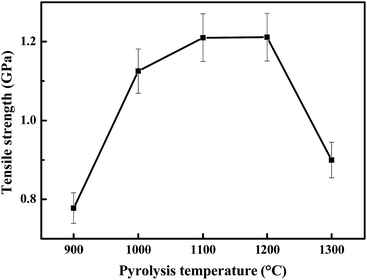
A fine-diameter silicon carbide (SiC) fiber is a promising reinforcing fiber for ceramic matrix composites with high temperature applications because of its high tensile strength and oxidation resistance. However, functional SiC fibers with microwave-absorbing properties are rarely reported. In this work, we report a new microwave-absorbing SiC-based fiber made from a new polymer containing titanium and boron (Si–C–Ti–B polymer) using a polymer precursor route. The evolution in morphology, microstructure and phase are studied by FT-IR, XRD, SEM, and TEM during the conversion of the polymer fiber into a ceramic fiber. The results show that the polymer fibers covert into inorganic fibers above 900 °C and maintain an amorphous state up to 1300 °C. The effect of pyrolysis-temperature (900–1300 °C) on the tensile strength, dielectric properties and microwave-absorption are also studied. The highest tensile strength of the obtained fiber is 1.2 GPa when produced at 1200 °C. The calculated reflection coefficient of the SiC-based fiber pyrolysed at 1200 °C with a thickness of 3.48 mm is less than −10 dB at the X band (8.2–12.4 GHz), which reveals that the obtained ceramic fiber has the potential to be a microwave-absorbing material. This study not only offers a new polymer precursor for new SiC-based fibers, but also provides a functional thermo-structural material.
Introduction
Silicon carbide (SiC) is an excellent thermo-structural material, because of its low density, high strength, high elastic modulus, excellent thermal shock resistance, and superior chemical inertness.1 An outstanding example of SiC as a thermo-structural material applied at high temperature was the fine-diameter continuous SiC fiber that was produced using a polymer precursor route.2,3 Furthermore, SiC was also recognized as a semiconductor material due to its large bandgap (2.3–3.3 eV)4 and it possesses very good microwave-absorbing properties. For example, polymer-derived SiC5,6 and SiC powder doped by other elements7,8 have been shown to have good microwave-absorbing capabilities. One can expect that the combination of these two properties will make SiC a unique functional thermo-structural material. However, the preparation of fine-diameter SiC fibers9 with microwave-absorbing properties still lacks study. As selected examples, Liu and her co-workers10 reported that a cobalt containing SiC fiber possessed microwave-absorbing properties with a calculated reflection coefficient (RC) lower than −3 dB at a thickness of 5.0 mm at the X-band (8.2–12.4 GHz); and Yin and his co-workers11 reported that the microwave-absorbing properties of a SiC fiber coated with boron nitride made using chemical vapour infiltration (CVI) were also excellent at the X-band.Fine-diameter SiC fibers are commonly used to prepare fiber-reinforced SiC matrix composites (SiCf/SiC), which can circumvent the brittle nature of monolithic SiC ceramic. Unlike monolithic SiC, the microwave-absorbing properties of SiCf/SiC were determined by the n-D architectural surface/structure,12 the chemical composition of the matrix,13 the interface,14 and its reinforced fiber. Obviously, the reinforced SiC fiber should also play an important role in the all-over microwave-absorbing properties of SiCf/SiC. Therefore, a fine-diameter SiC fiber with microwave-absorbing properties is desired for SiCf/SiC or other composites to be applied at high temperatures. Herein, we report a new fine-diameter SiC-based fiber as an excellent electromagnetic wave absorbing material at the X-band (8.2–12.4 GHz) made from a new polymer precursor. The obtained SiC-based fibers can serve as potential functional thermo-structural materials when applied at high temperatures.
Experimental
Materials
All manipulations were carried out under an argon atmosphere using standard Schlenk techniques unless otherwise stated. Polycarbosilane was synthesized following the work described in the literature15 with a softening temperature of ca. 198 °C. The liquid polysilane was prepared as in the previously reported procedure16 with a number average molecular weight (Mn) of ca. 300–600 (D = 1.08). Ti(OBu)4 was further purified by distillation under vacuum prior to use. Hexane was distilled under nitrogen from sodium benzophenone before use. Other commercially available reagents were used as received.Polymer syntheses
12.2 g of liquid polysilane was introduced into a 50 mL Schlenk flask under an argon atmosphere, then 4.1 g of Ti(OBu)4 and 5.1 g of B(OBu)3 were introduced into the Schlenk flask with stirring at room temperature for 10 min to give a pale yellow solution. Subsequently, the reaction mixture was heated up to 292 °C for 2 h under an argon flow to give a dark-blue viscous product, which was then mixed with 37.8 g of polycarbosilane in hexane at room temperature. Finally, the solvent was removed under vacuum at room temperature, and the resultant blue polymer (Si–C–Ti–B polymer) was further dried at 80 °C for at least 12 h under vacuum. Yield: 53.0 g, 89.5%. IR (KBr): 2950 cm−1 (νas(C–H)), 2902 (νs(C–H)), 2100 (ν(Si–H)). 1H NMR (300.13 MHz, CDCl3): δ 3.5–5.4 (br, SiH), −1 to 1.5 (br, CH). 29Si{1H} NMR (59.63 MHz, CDCl3): δ −0.2 (br, SiC4), −17.5 (br, HSiC3). Mn = 1276 (D = 2.95). Elemental analysis: C, 39.4%; Si, 50.3%; H, 3.7%; O, 4.1%; Ti, 1.6%; B, 1.0%.Preparation of polymer fiber
The obtained polymer was placed into the reservoir of a laboratory piston-type melt-spinning machine (MMCH05, Chemat, Northridge, CA). It was then heated up to 258 °C under the protection of an argon atmosphere for 4 h. Then, the molten polymer was extruded from the single capillary (0.2 mm) as a filament, which was collected continuously on a bobbin at a winding speed of 450 m min−1.Curing and pyrolysis
The as-spun fibers were cut into ca. 75 mm lengths and placed into a tube furnace. Then they were cured in air at 210 °C for 90 min. The pyrolysis of the cured fibers was carried out at a set temperature (900–1300 °C) in N2 gas flowing at 400 cm3 min−1. The heating rate from room temperature to 800 °C and from 800 °C to the set temperature was 5 °C min−1 and 3 °C min−1, respectively.Characterization
Fourier transform infrared (FT-IR) spectra were recorded on a Nicolet Avatar 360 apparatus (Nicolet, USA) using the potassium bromide (KBr) pressed-disk technique in the 4000–400 cm−1 frequency range. Raman spectra were recorded on a LabRam I (Dilor, France) spectrometer employing a semiconductor laser (λ = 532 nm) for characterization of the various carbon states. Gel permeation chromatography (GPC) (Agilent 1100 system, Agilent, USA) measurements were performed at 30 °C with tetrahydrofuran as the eluent (1.0 mL min−1). NMR experiments were carried out on a Bruker Advance II-300 spectrometer (300 MHz, Bruker, Germany) for 1H and 29Si{1H} spectra. The 1H and 29Si chemical shifts are relative to tetramethylsilane (TMS) (assigned to 0 ppm). The chemical composition (Si, Ti and B) was determined using inductively coupled plasma optical emission spectroscopy using an ICP-OES (IRIS Intrepid XSP, Thermo fisher, USA) spectrometer. The oxygen and carbon content was ascertained using an oxygen nitrogen analyzer (EMGA-620W, Horiba, Japan) and a carbon sulfur analyzer (EMIA-320V, Horiba), respectively. The tensile strength and elastic modulus of the monofilament were ascertained using a universal testing machine (AG-X plus, Shimadzu, Japan). The gauge length was 25 mm and the crosshead speed was 1 mm min−1. At least 20 effective measurements were conducted and the average value was used. Scanning electron microscopy (SEM, SU-70, Hitachi, Japan) was used to observe the fracture and surface morphology. Transmission electron microscopy (TEM, JEM-2100, Jeol, Japan) was performed to reveal the microstructure. The crystallization behavior of the pyrolysis SiC-based fiber was monitored using X-ray powder diffraction (XRD, D8 Advance, Bruker, Germany). The relative complex permittivity was recorded using a vector network analyzer (N5222A, Agilent Technologies, USA) at a frequency ranging from 8.2 to 12.4 GHz (X-band). The samples were prepared by dispersing a short fiber into 65 wt% wax paraffin uniformly, and pressing it into coaxial rings with an outer diameter of 7.0 mm and an inner diameter of 3.04 mm. The material measurement software used was Agilent 85071E and the measurement route was the transmission line method.Results and discussion
Preparation of SiC-based fiber
The obtained blue polymer (Si–C–Ti–B polymer) has a molecular weight (Mn) of 1276 (D = 2.95) measured by gel permeation chromatography (GPC). The 29Si{1H} NMR spectrum (see the ESI†) shows two broad signals at ca. −0.2 and −17.5 ppm, which are assigned to SiC4 and HSiC3 groups,21 respectively. The FT-IR spectrum (see the ESI†) also shows a characteristic Si–H stretch at ca. 2100 cm−1, which is similar to that of polytitanocarbosilane.21 The content of boron and titanium, detected using an inductively coupled plasma optical emission spectrometer (ICP-OES), in the resultant polymer was 1.6% and 1.0%, respectively. These results indicated that the obtained polymer (Si–C–Ti–B polymer) had a similar structure to the reported polytitanocarbosilane,21 except that it contained boron.
Melting-spin and its conversion to a ceramic fiber
The obtained polymer with very good spinnability was then spun into a continuous preceramic polymer fiber (Fig. 1B, also called the “Si–C–Ti–B polymer fiber”) using the melting-spin technique at 244 °C. And then, it was cut into short fibers with lengths of ca. 75 mm and crosslinked in air at 210 °C. The resultant infusible fiber was then further pyrolysed in N2 at 900–1300 °C (no tension was applied) to give SiC-based ceramic fibers (Fig. 1C, shrunk to ca. 60 mm).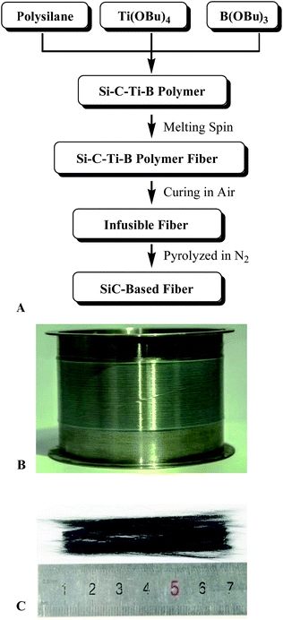 | ||
| Fig. 1 (A) The flowchart of preparation of the SiC-based fiber, (B) Si–C–Ti–B polymer fiber, and (C) SiC-based ceramic fiber. | ||
To understand the conversion of the organic polymer into the inorganic fiber,22 we monitored the resultant fibers at different treatment temperatures using FT-IR analysis. As shown in Fig. 2A, the absorption peaks of the polymer fiber at 2100 cm−1, 1020 cm−1 and 2850–2980 cm−1 are attributed to the stretches of Si–H, Si–C, and C–H in the HSiC3, Si–CH2–Si and CHn (n = 1, 2 or 3) groups, respectively. The absorption peak at 1250 cm−1 is assigned to the bending of C–H in the Si–CH3 group. These results show that there is no significant difference between the as-synthesised polymer and the polymer fiber after melting-spin.
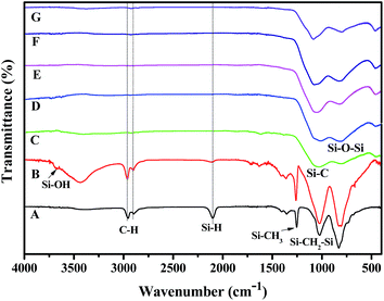 | ||
| Fig. 2 The FT-IR spectra of (A) the polymer fiber, (B) the infusible preceramic fiber and the ceramic fiber obtained at (C) 900 °C, (D) 1000 °C, (E) 1100 °C, (F) 1200 °C, and (G) 1300 °C. | ||
Major changes can be found between the polymer fiber (Fig. 2A), the infusible polymer fiber (Fig. 2B) and the ceramic fiber (Fig. 2C). After air curing, the absorption intensity at 2100 cm−1 (Si–H stretch) decreased, while the absorption intensity around 3500 cm−1 (broad, O–H stretch) increased. The decrease in intensity at 2100 cm−1 (Si–H stretch) indicated the consumption of the Si–H group during the curing process. And the appearance of a broad peak around 3500 cm−1 (O–H stretch) indicated the formation of OH groups after oxidative curing. In agreement with the air curing of polytitanocarbosilane,21 the purpose of the crosslinking of the polymer fiber was achieved by the oxidative reaction of Si–H with air to form a Si–O–Si substructure via the dehydration of the Si–OH groups. When the infusible fibers were pyrolysed at 900 °C or above, the absorptions around 2850–2980 cm−1 (C–H stretch), 2100 cm−1 (Si–H stretch), and 1250 cm−1 (C–H bending in the Si–CH3 group) disappeared. This indicated the conversion of the organic polymer into a ceramic fiber was almost complete at this or a higher temperature, since the SiC ceramic did not contain any C–H or Si–H groups. The formation of the SiC-based ceramic species can be confirmed by the broad absorption peaks at 780 cm−1, 1100 cm−1 and 800–1030 cm−1 (Fig. 2C–G), which are attributed to the stretches of Si–C and Si–O in the amorphous SiC framework and the Si–O–Si substructure, respectively. Thus, our titanium and boron containing polymer (Si–C–Ti–B polymer) with low cost and good spinnability represents a new polymer precursor for new ceramic fibers.
Characterization of the SiC-based fiber
As shown in Fig. 4, the surfaces of the obtained ceramic fibers are smooth when the fiber is pyrolysed at 900–1200 °C. When the pyrolysis-temperature is 1300 °C, the ceramic fiber appears to have a rough surface, and there are a few tiny pores (with a diameter of ca. 120 nm) present in the fiber. This result indicates that the decrease in the tensile strength at 1300 °C could be caused by the formation of these tiny pores, which may be generated during the decomposition of the meta-stable Si–C–O phase.24
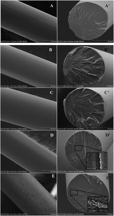 | ||
| Fig. 4 SEM photos of the obtained ceramic fibers pyrolysed at (A & A′) 900 °C, (B & B′) 1000 °C, (C & C′) 1100 °C, (D & D′) 1200 °C, and (E & E′) 1300 °C. | ||
To further understand the aforementioned results, we next studied the obtained ceramic fibers by XRD characterization. The results showed (Fig. S5, see the ESI†) that no diffraction peaks were found when the treatment temperature was 1300 °C or lower, which indicated that there is no visible crystallization of β-SiC at these pyrolysis-temperatures. The TEM studies also revealed the amorphous structures (no obvious lattice fingers or diffraction rings) of the ceramic fibers prepared from 1000 to 1300 °C (Fig. S6, see the ESI†), which were consistent with the XRD analysis.
It is well-known that a Si–C–O fiber prepared from polycarbosilane would decompose and generate a β-SiC nano-crystal, pyrolytic carbon and gas species at 1100 °C or higher.25 The crystallization of β-SiC has also been found in Si–C–Ti–O fibers at 1100 °C or higher.26 Therefore, the best strength of these two fibers could not be found above 1100 °C. In contrast, our fiber can reach a maximum strength at 1200 °C due to its amorphous structure. The crystallization of β-SiC can be retarded, and the obtained ceramic fibers remained in their amorphous form after doping with boron, which may be incorporated into the Si–C–O skeleton as a BO3 substructure (the presence of boron and titanium in the ceramic fiber can be identified using the ICP-OES data as shown in Table S1, see the ESI†). After curing in air, more oxygen was introduced into the Si–C–O meta-stable phase by forming Si–O bonds. Thus, the high content of oxygen could be responsible for the low crystallization degree of β-SiC in the ceramic fiber.
For our SiC-based fibers, their relationship between the permittivity and frequency is shown in Fig. 5. The real part of the permittivity has a tendency to increase when the pyrolysis-temperature is lower than 1200 °C. For example, when the frequency is 10.2 GHz, the real part ε′ is equal to 3.0, 3.9, 5.5, and 5.8 at 900, 1000, 1100, and 1200 °C, respectively. However, the real part of the permittivity decreases to 2.7 (frequency is 10.2 GHz) when annealed at 1300 °C. As shown in Fig. 5B, the loss tangent increases when the annealing-temperature rises, and reaches a maximum at 1200 °C.
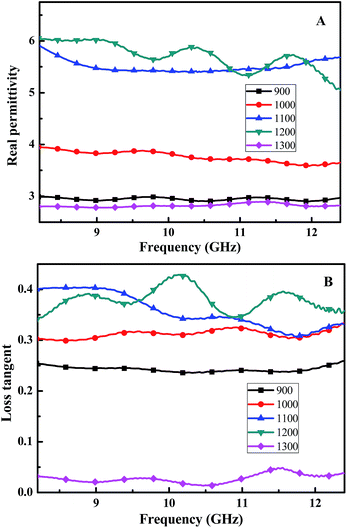 | ||
| Fig. 5 (A) Real part of the relative complex permittivity, and (B) the loss tangent of the Si–C–Ti–B fibers pyrolysis from 900 to 1300 °C. | ||
In general, the change in the dielectric properties of the SiC-based materials is mainly caused by variation in the conductivity,13a which is governed by the content and degree of order of pyrolytic carbon in the polymer-derived SiC-based ceramic.12b The carbon structure of the fiber was, therefore, studied using Raman analysis. As shown in Fig. 6, all the spectra of the samples show the presence of free carbon detected as D (ca. 1350 cm−1, amorphous carbon) and G bands (ca. 1600 cm−1, ordered carbon).28 Both signals (D and G bands) are slightly increased when the pyrolysis-temperature rises up to 1200 °C, which indicates the generation of free carbon and an enhancement in the degree of order.
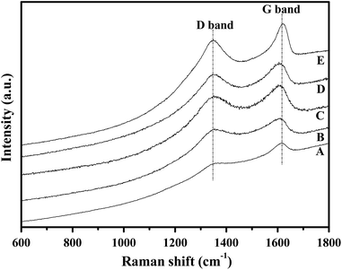 | ||
| Fig. 6 Raman spectra of the obtained ceramic fibers pyrolysed at (A) 900 °C, (B) 1000 °C, (C) 1100 °C, (D) 1200 °C, and (E) 1300 °C. | ||
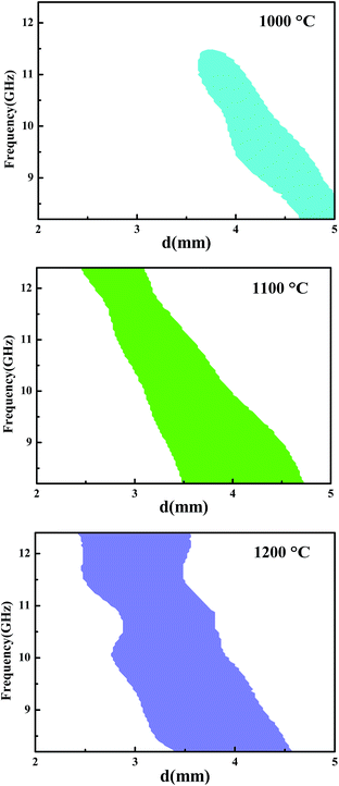
To determine the microwave-absorbing capacity of our fibers, we tried to calculate the frequency as a function of the sample thickness corresponding to a calculated RC ≤ −10 dB (Fig. 7) based on transmission line theory. In the selected thickness range from 2 to 5 mm, no regions corresponding to a RC ≤ −10 dB could be found after the fiber was annealed at 900 °C and 1300 °C. Interestingly, regions with different areas appeared when the fiber was annealed at 1000, 1100, or 1200 °C. For example, when the fibers were annealed at 1200 °C and reached a layered thickness of 3.48 mm, the RC would be lower than −10 dB in the whole X band (Fig. 7C). This result indicated that our SiC-based fiber annealed at 1200 °C had the strongest capacity for electromagnetic wave absorption among all of the annealed fibers.
Conclusions
A new SiC-based fiber containing titanium and boron was prepared in the present study from a new polymer precursor. The fiber is amorphous and its tensile strength and microwave-absorbing capacity at the X band are best when it was pyrolysed at 1200 °C. The obtained ceramic fiber has the potential to serve as a microwave-absorbing thermo-structural material.Acknowledgements
This work was supported by the National Natural Science Foundation of China (Grant No: 21302158).References
- (a) G. L. Harris, Properties of Silicon Carbide, Institution of Electrical Engineering and Technology, London, UK, 1995 Search PubMed; (b) H. O. Pierson, Handbook of Refractory Carbides and Nitrides, Noyes Publications, Westwood, NJ, USA, 1996 Search PubMed.
- (a) S. Yajima, J. Hayashi and M. Omori, Chem. Lett., 1975, 4, 931–934 CrossRef; (b) S. Yajima, J. Hayashi, M. Omori and K. Okamura, Nature, 1976, 261, 683–685 CrossRef CAS; (c) S. Yajima, Philos. Trans. R. Soc., A, 1980, 294, 419–426 CrossRef CAS.
- A. R. Bunsell and A. Piant, J. Mater. Sci., 2006, 41, 823–839 CrossRef CAS.
- (a) S. E. Saddow and A. Agarwal, Advances in Silicon Carbide Processing and Applications, Artech House, Boston, MA, USA, 2004 Search PubMed; (b) H. Morkoc, S. Strite, G. B. Gao, M. E. Lin, B. Sverdlov and M. Burns, J. Appl. Phys., 1994, 76, 1363–1398 CrossRef CAS.
- W. Duan, X. Yin, Q. Li, L. Schlier, P. Greil and N. Travitzky, J. Eur. Ceram. Soc., 2016, 36, 3681–3689 CrossRef CAS.
- (a) Q. Li, X. Yin, W. Duan, L. Kong, B. Hao and F. Ye, J. Alloys Compd., 2013, 565, 66–72 CrossRef CAS; (b) Y. Shi, F. Luo, D. Ding, F. Wan, W. Zhou and D. Zhu, Int. J. Appl. Ceram. Technol., 2016, 13, 17–22 CrossRef CAS; (c) D. Ding, W. Zhou, X. Zhou, F. Luo and D. Zhu, Trans. Nonferrous Met. Soc. China, 2012, 22, 2726–2729 CrossRef CAS; (d) X. Yuan, L. Cheng, Y. Zhang, S. Guo and L. Zhang, Mater. Des., 2016, 92, 563–570 CAS; (e) D. Zhao, F. Luo and W. Zhou, J. Alloys Compd., 2010, 490, 190–194 CrossRef CAS.
- (a) Z. Li, W. Zhou, X. Su, F. Luo, Y. Huang and C. Wang, J. Alloys Compd., 2011, 509, 973–976 CrossRef CAS; (b) S. Agathopoulos, Ceram. Int., 2012, 38, 3309–3315 CrossRef CAS; (c) X. Su, W. Zhou, Z. Li, F. Luo, H. Du and D. Zhu, Mater. Res. Bull., 2009, 44, 880–883 CrossRef CAS.
- (a) J. Yuan, H. Yang, Z. Hou, W. Song, H. Xu, Y. Kang, H. Jin, X. Fang and M. Cao, Powder Technol., 2013, 237, 309–313 CrossRef CAS; (b) Z. Li, W. Zhou, X. Su, Y. Huang, G. Li and Y. Wang, J. Am. Ceram. Soc., 2009, 92, 2116–2118 CrossRef CASD. Li, H. Jin, M. Cao, T. Chen, Y. Dou, B. Wen and S. Agathopoulos, J. Am. Ceram. Soc., 2011, 94, 1523–1527 CrossRef CAS; (c) Z. Li, W. Zhou, F. Luo, Y. Huang, G. Li and X. Su, Mater. Sci. Eng. B, 2011, 176, 942–944 CrossRef CAS; (d) B. Zhang, J. Li, J. Sun, S. Zhang, H. Zhai and Z. Du, J. Eur. Ceram. Soc., 2002, 22, 93–99 CrossRef CAS; (e) X. Su, W. Zhou, J. Xu, Z. Li, F. Luo and D. Zhu, J. Alloys Compd., 2010, 492, L16–L19 CrossRef CAS; (f) F. Luo, X. Liu, D. Zhu and W. Zhou, J. Am. Ceram. Soc., 2008, 91, 4151–4153 CrossRef CAS.
- (a) Y. Kagawa, K. Matsumura, H. Iba and Y. Imahashi, J. Mater. Sci., 2007, 42, 1116–1121 CrossRef CAS; (b) E. Tan, Y. Kagawa and A. F. Dericioglu, J. Mater. Sci., 2009, 44, 1172–1179 CrossRef CAS; (c) F. Ye, L. Zhang, X. Yin, Y. Liu and L. Cheng, J. Mater. Sci. Technol., 2013, 29, 55–58 CrossRef CASX. G. Liu, Y. D. Wang, L. Wang, J. G. Xue and X. Y. Lan, Int. J. Inorg. Mater., 2010, 25, 1–4 Search PubMed.
- A. Liu, J. Chen, S. Ding, Y. Yao, L. Liu, F. Li and L. Chen, J. Mater. Chem. C, 2014, 2, 4980–4988 RSC.
- F. Ye, L. Zhang, X. Yin, Y. Liu and L. Cheng, Appl. Surf. Sci., 2013, 270, 611–616 CrossRef CAS.
- (a) D. Ding, Advances in ceramic matrix composites, ed. I. M. Low, Woodhead Publishing Limited, Oxford, 2014, pp. 9–26 Search PubMed; (b) H. Tian, H. Liu and H. Cheng, Compos. Sci. Technol., 2014, 90, 202–208 CrossRef CAS; (c) D. Ding, W. Zhou, B. Zhang, F. Luo and D. Zhu, J. Mater. Sci., 2011, 46, 2709–2714 CrossRef CAS; (d) H. Liu, H. Tian and H. Cheng, J. Nucl. Mater., 2013, 432, 57–60 CrossRef CAS; (e) Z. Chu, H. Cheng, Y. Zhou, Q. Wang and J. Wang, Mater. Des., 2010, 31, 3140–3145 CrossRef CAS.
- (a) Q. Li, X. Yin, W. Duan, L. Kong, X. Liu, L. Cheng and L. Zhang, J. Eur. Ceram. Soc., 2014, 34, 2187–2201 CrossRef CAS; (b) X. Yu, W. Zhou, F. Luo, W. Zheng and D. Zhu, J. Alloys Compd., 2009, 479, L1–L3 CrossRef CAS; (c) L. Chen, X. Yin, X. Fan, M. Chen, X. Ma, L. Cheng and L. Zhang, Carbon, 2015, 95, 10–19 CrossRef CAS; (d) Y. Mu, W. Zhou, Y. Hu, D. Ding, F. Luo and Y. Qing, J. Alloys Compd., 2015, 637, 261–266 CrossRef CAS.
- (a) H. Liu and H. Tian, J. Eur. Ceram. Soc., 2012, 32, 2505–2512 CrossRef CAS; (b) H. Song, W. Zhou, F. Luo, Z. Huang, Y. Qing, M. Chen and Y. Mu, Mater. Sci. Eng. B, 2015, 195, 12–19 CrossRef CAS; (c) Y. Shi, F. Luo, D. Ding, Y. Mu, W. Zhou and D. Zhu, Trans. Nonferrous Met. Soc. China, 2015, 25, 1484–1489 CrossRef CAS.
- M. Birot, E. Bacque, J. P. Pillot and J. Dunogues, J. Organomet. Chem., 1987, 319, 41–44 CrossRef.
- Z. Xie, X. Cheng and Q. Gao, J. Mater. Eng., 2006, S1, 370–373 Search PubMed.
- (a) S. Yajima, M. Omori, J. Hayashi and K. Okamura, Chem. Lett., 1976, 5, 551–554 CrossRef; (b) S. Yajima, Y. Hasegawa, J. Hayashi and M. Limura, J. Mater. Sci., 1978, 13, 2569–2576 CAS; (c) Y. Hasegwa, M. Iimura and S. Yajima, J. Mater. Sci., 1980, 15, 720–728 CrossRef.
- (a) R. M. Laine and F. Babonneau, Chem. Mater., 1993, 5, 260–279 CrossRef CAS; (b) M. Birot, J. P. Pillot and J. Dunogues, Chem. Rev., 1995, 95, 1443–1477 CrossRef CAS.
- (a) K. Okamura, Composites, 1987, 18, 107–120 CrossRef CAS; (b) H. Ichikawa and T. Ishikawa, Comprehensive Composite Materials, ed. A. Kelly, C. Zweben and T. W. Chou, Elsevier, Amsterdam, 2000, vol. 1 Search PubMed.
- (a) G. M. He, PhD thesis, Xiamen University, Xiamen, China, Nov, 2011; (b) Y.-C. Song, C.-X. Feng, Y.-L. Liu, Y. Lu and Z.-L. Tan, J. Mater. Sci. Lett., 1992, 11, 899–902 CrossRef.
- S. Yajima, T. Iwai, T. Yamamura, K. Okamura and Y. Hasegawa, J. Mater. Sci., 1981, 16, 1349–1355 CrossRef CAS.
- K. Okamura, T. Shimoo, K. Suzuya and K. Suzuki, J. Ceram. Soc. Jpn., 2006, 114, 445–454 CrossRef CAS.
- (a) Z. Chu, C. Feng, Y. Song, J. Wang, Y. Wang and X. Li, Sci. Eng. Compos. Mater., 2002, 10, 131–140 CAS; (b) C. Zheng, X. Li, Z. Chu and C. Feng, J. Chin. Ceram. Soc., 2005, 33, 687–692 Search PubMed.
- (a) L. Porte and A. Sartre, J. Mater. Sci., 1989, 24, 271–275 CrossRef CAS; (b) C. Laffon, A. M. Flank, P. Lagarde, M. Laridjani, R. Hagege, R. Olry, J. Cotteret, J. Dixmier, J. L. Miquel, H. Hommel and A. P. Legrand, J. Mater. Sci., 1989, 24, 1503–1512 CrossRef CAS.
- (a) Y. Hasegawa and K. Okamura, J. Mater. Sci., 1983, 18, 3633–3648 CrossRef CAS; (b) G. Simon and A. R. Bunsell, J. Mater. Sci., 1984, 19, 3658–3670 CrossRef CAS.
- (a) T. Yamamura, T. Ishikawa, M. Shibuya, T. Hisayuki and K. Okamura, J. Mater. Sci., 1988, 23, 2589–2594 CrossRef CAS; (b) M. Narisawa, Y. Itoi and K. Okamura, J. Mater. Sci., 1995, 30, 3401–3406 CrossRef CAS; (c) Y. Yu, Y. Guo, X. Cheng and Y. Zhang, J. Inorg. Organomet. Polym., 2010, 20, 714–719 CrossRef CAS.
- P. A. Miles, W. B. Westphal and A. Von Hippel, Rev. Mod. Phys., 1957, 29, 279–307 CrossRef CAS.
- (a) Y. Sasaki, Y. Nishina, M. Sato and K. Okamura, J. Mater. Sci., 1987, 22, 443–448 CrossRef CAS; (b) S. Kaur, G. Mera, R. Riedel and E. Ionescu, J. Eur. Ceram. Soc., 2016, 36, 967–977 CrossRef CAS.
Footnote |
| † Electronic supplementary information (ESI) available. See DOI: 10.1039/c7ra00175d |
| This journal is © The Royal Society of Chemistry 2017 |

