
 Open Access Article
 This Open Access Article is licensed under a Creative Commons Attribution-Non Commercial 3.0 Unported Licence
The degradation of azo dye with different cathode and anode structures in biofilm electrode reactors
Xian Cao,
Feng Gu,
Hui Wang,
Zhou Fang and
Xian-ning Li *
*
School of Energy and Environment, Southeast University, Nanjing 210096, China. E-mail: loveveolkswagen@163.com; 504629959@qq.com; lwcq306@163.com; shaka-fz@163.com; lxnseu@163.com; Fax: +86 25 83795618; Tel: +86 137 76650963
First published on 20th March 2017
Abstract
In this study, biofilm electrode reactors (BERs) were constructed to degrade the azo dye Reactive Brilliant Red (RBR) X-3B. Three different BERs, namely, cathodes with differently structured reactors, cathodes filled with a granular activated carbon (GAC) reactor, and a dimensionally stable anode (DSA) electrode anode reactor, were individually studied to investigate their influence on the removal of both X-3B and chemical oxygen demand (COD). Experimental results showed that it was the internal resistance rather than the total surface area of the cathode that influenced the X-3B removal efficiency in the different cathode reactors. The smaller the internal resistance, the larger the current in the reactor. The larger the current in the whole system, the more electrons that could be utilized for the reduction of X-3B, resulting in higher removal efficiency. The cathode filled with a GAC-BER did not improve the COD removal efficiency, while the X-3B removal efficiency actually declined. Using the DSA electrode as an anode increased the current in the system and improved the removal efficiency. Scanning electron microscopy results showed that the DSA electrode anode had a longer service life than a graphite anode. UV-vis spectral analysis determined that the conjugate system in X-3B was destroyed.
1. Introduction
Azo dyes, which are aromatic compounds with one or more –N![[double bond, length as m-dash]](https://www.rsc.org/images/entities/char_e001.gif) N– groups,1 are widely used in the textile, cosmetic, and paper industries.2 The discharge of azo dye wastewater to surface water without appropriate treatment could lead to a series of environmental problems, such as poor appearance of the water, deterioration of receiving water quality, and restriction in light penetration.3,4 Several remedial techniques have been developed to remove azo dyes from wastewater. These include physico-chemical technologies, such as adsorption, coagulation, and flocculation advanced oxidation,5 as well as biological treatment processes, such as the use of bacteria and fungi.6,7 However, the application of these methods has limitations, such as complex operational requirements, high operating and maintenance costs, and low treatment efficiency.7,8
N– groups,1 are widely used in the textile, cosmetic, and paper industries.2 The discharge of azo dye wastewater to surface water without appropriate treatment could lead to a series of environmental problems, such as poor appearance of the water, deterioration of receiving water quality, and restriction in light penetration.3,4 Several remedial techniques have been developed to remove azo dyes from wastewater. These include physico-chemical technologies, such as adsorption, coagulation, and flocculation advanced oxidation,5 as well as biological treatment processes, such as the use of bacteria and fungi.6,7 However, the application of these methods has limitations, such as complex operational requirements, high operating and maintenance costs, and low treatment efficiency.7,8
In recent years, bioelectrochemical systems have been explored to reduce refractory substances including nitro aromatics,9 antibiotics,10 heavy metals11,12 and azo dyes13 into biodegradable and less toxic products.4 A moderate electrical current supply on an anode can provide electrons for the cathodic reduction of refractory substances. The energy consumption would be lower and the operational requirements would be much less complex than those for conventional physico-chemical technologies or biological treatment processes,14,15 while the treatment efficiency would be increased at the same time. In recent years, the biofilm electrode reactors (BERs) have been investigated for reduction of nitrate,16 hydrocarbon pollutant,17 chlorinated organic compound,18 perchlorate,19 azo dye20 and antibiotics.21 Previous studies demonstrated that some operational parameters can affect the removal of refractory substances BERs, such as the voltage applied, different reactor materials, and co-substrates. Mu14 et al. reported that the decolorization efficiency of azo dye, AO7, was increased from 70.9% to 98.7% by controlling the cathodic electrode potential in the range of −350 to −550 mV vs. a standard hydrogen electrode (SHE). Kong22 et al. reported that 4-chlorophenol dechlorination could be improved with composite materials rather than carbon-based materials. Sun23 et al. reported that a BER supplied with glucose had higher removal efficiency of Alizarin Yellow R than a BER supplied with acetate. In addition, different electrode materials were used in BERs. Zhou24 et al. reported a 6-times higher maximum biocurrent density was obtained by using a carbon-coated hematite electrode. Zhou25 et al. used a third electrode of graphite in three-dimensional BER which made the 24% higher Fe(III) EDTA reduction efficiency.
However, few studies have reported the removal efficiency could be affected by the use of different cathodes and anodes in BER. In this study, the treatment efficiency of cathodes with different structures, including a cathode filled with granular activated carbon (GAC), and anodes composed of different materials, was thoroughly evaluated in BER. Reactive Brilliant Red (RBR) X-3B was used as a model azo dye because it is often present in dyeing wastewater. The removal of RBR X-3B was investigated under different conditions in BERs. Scanning electron microscopy (SEM) was used to examine the anodes composed of different materials.
2. Materials and methods
2.1 Reactor configuration
Fig. 1 shows a schematic diagram of the reactor used in this study. It was made of polycarbonate plastic, with dimensions of 15 cm (diameter) and 25 cm (height). The effective working volume of the reactor was 3.3 L. It had a water inlet at the bottom and a water outlet at the top. An electric mixer with variable timing was used for intermittent stirring. The frequency was 15 min of stirring every 6 h. The X-3B artificial wastewater was continuously pumped into the reactors from the water intake at the bottom of the reactors by a peristaltic pump (BT-100; Baoding Longer Precision Pump Co., Ltd, Baoding, China). The hydraulic retention time was 3.8 days. A DC power supply (IT6322; ITECH Electronic Co., Ltd, Nanjing, China) provided the current for each reactor.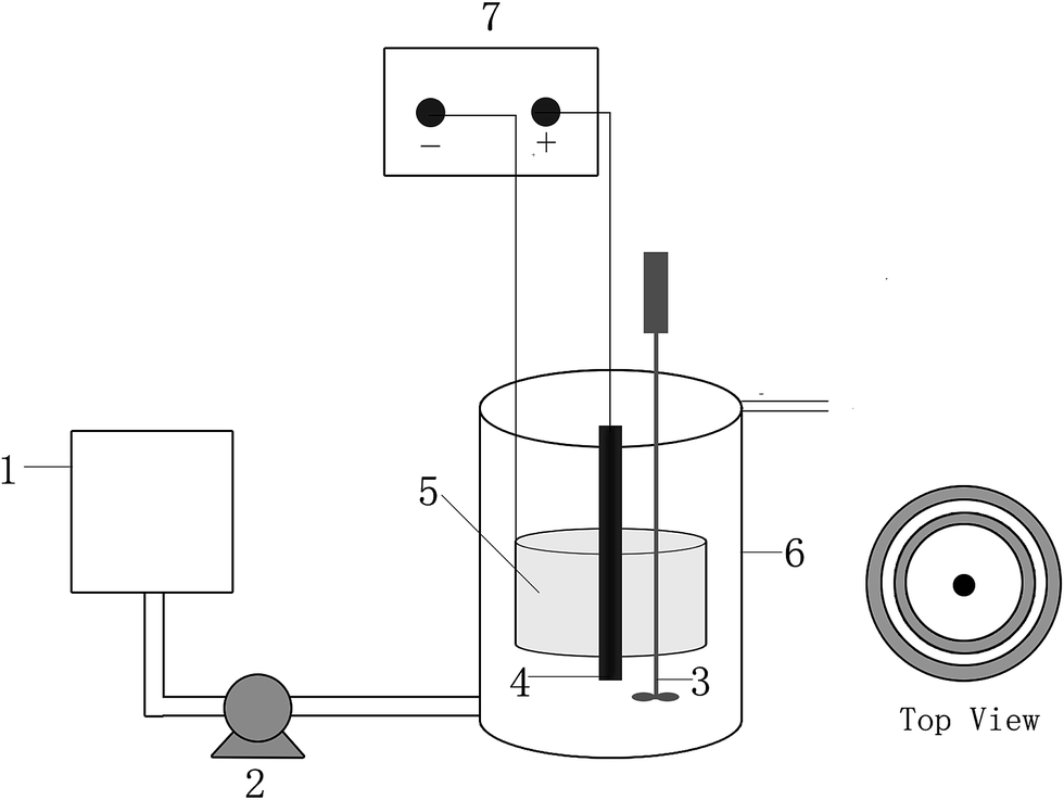 | ||
| Fig. 1 Schematic diagram of the reactor: (1) inlet tank; (2) peristaltic pump; (3) stirrer; (4) the anode; (5) the cathode; (6) the reactor; (7) DC regulated power supply. | ||
2.2 System operation
All of the reactors were red with nutrient solution with the following composition (per liter): 400 mg of glucose, 330 mg of NaCl, 134 mg of NH4Cl, 33 mg of NaH2PO4, 18 mg of Na2HPO4, 340 mg of NaHCO3, 15 mg of MgSO4·7H2O, 2 mg of ZnSO4·7H2O, 2.2 mg of MnSO4·H2O, 1 mg of FeSO4, 0.24 mg of CoCl2·6H2O, 15 mg of CaCl2, and 1.17 mg of (NH4)6Mo7O24·4H2O. Five hundred milliliters of anaerobic sludge (mixed liquor suspended solids: 50 g L−1, chemical oxygen demand (COD): 5–10 g L−1, total carbohydrate: 0.3–2 g L−1) sampled from the East City Municipal Wastewater Treatment Plant of Nanjing, China, was introduced into all of the reactors for microbial inoculation. Analytical grade RBR X-3B was used without further purification (Jiaying Chemical Co., Ltd., Shanghai, China). In the whole experiment, the influent pH values were about 7.6 and the effluent pH values were maintained at 7.75–8.05 which fluctuated weakly due to the presence of NaHCO3 as a chemical buffer in all reactors. All experiments were conducted at 25 ± 1 °C in a controlled-climate room. All of the data shown in this study are the average of three measurements.The experiment consisted of three stages. In the first stage, to investigate the impact of the different surface areas and structures of the cathode reactors on X-3B removal efficiency, four types of BER, with two types of different single cathode and two types of different double cathode (inner cathode and outer cathode) were constructed. The structural parameters of these cathodes are listed in Table 1. The cathode was composed of a stainless steel (1 mm thickness) ring and activated carbon fiber (ACF). The ACF (1.0 mm in thickness) was attached to both the inner and the outer surfaces of the stainless steel ring using conductive adhesive (Nanjing Xilite Adhesive Co., Ltd., Nanjing, China). A graphite rod (18 cm in length and 2 cm in diameter) was installed in the center of each type of reactor as an anode, with the cathode surrounding it. A single cathode and anode were connected by titanium wire (1 mm in diameter) to a DC power supply (1 V DC) to create a loop circuit, while the double cathode, with a parallel connection, was connected to the anode and by titanium wire to the DC power supply. 5# BER had the same setup with 1# BER except the cathode and anode were not connected DC power supply. The concentration of X-3B was 100 mg L−1 at the beginning of the experiment, and reached 150 and 200 mg L−1 on days 46 and 60, respectively.
| Number | 1# | 2# | 3# | 4# | 5# | ||
|---|---|---|---|---|---|---|---|
| Inner cathode | Outer cathode | Inner cathode | Outer cathode | ||||
| Height (mm) | 90 | 135 | 40 | 40 | 60 | 60 | 90 |
| Diameter (mm) | 80 | 80 | 70 | 110 | 70 | 110 | 80 |
| Superficial area (m2) | 0.045 | 0.068 | 0.045 | 0.068 | 0.045 | ||
In the second stage, to investigate the X-3B removal efficiency in a cathode filled with a GAC (3–5 mm in diameter with a specific area of 500–900 m2 g−1) reactor, GAC-BERs were constructed. In these reactors, the cathode was the same as in the 3# BER; GAC was used to fill the space between the inner and outer cathodes and then wrapped with gauze. The double cathode was connected to the graphite rod anode and by titanium wire to a DC power supply (1 V DC). The concentration of X-3B was 100 mg L−1 at the beginning of the experiment, and reached 150 and 200 mg L−1 on days 46 and 60, respectively.
In the third stage, to investigate the influence of the X-3B removal efficiency in different anode material reactors, Ti/IrO2–Ta2O5-coated dimensionally stable anode (DSA; Baoji Ruicheng Co., Ltd., China; 18 cm in length and 2 cm in diameter) BERs were built. The structure of a DSA-BER was the same as that of the 3# BER, except for the anode. The concentration of X-3B was 200 mg L−1.
2.3 Analytics and calculations
UV-vis spectrophotometer (UV9100, Lab Tech Ltd, Beijing, China) was used to investigate the influent of BERs over ranging from 190 to 600 nm. Meanwhile, to determine the X-3B removal efficiency, influent absorbance values (A1) and effluent absorbance values (A2) were measured, and the X-3B removal efficiency (E) was calculated as shown in eqn (1)| E = (A1 − A2)/A1 × 100% | (1) |
The influent chemical oxygen demand (COD) concentrations (C1) and effluent COD concentrations (C2) were measured according to standard methods. The COD removal efficiency (C) was calculated as shown in eqn (2)
| C = (C1 − C2)/C1 × 100% | (2) |
All samples were filtered through a 0.45 lm syringe filter to remove suspended solids from the liquid media prior to the measurements.1,26
The internal resistance was calculated by the linear region of polarization curve.27
For scanning electron microscopy (SEM) observation, the electrode was immobilized in a solution of glutaraldehyde for 24 h at 4 °C, then processed through an ethanol dehydration series (i.e., 30, 50, 70, 85, 95 and 100%, v/v, ethanol, 0.5 h each treatment), dried with the critical point drying method and evaluated using scanning electron microscopy (HIMADZU SSX-550, Shimadzu, Japan).20
3. Results and discussion
3.1 X-3B removal efficiencies in reactors with cathodes with different surface areas and structures
The influence of reactors with cathodes with different surface areas and structures on X-3B removal efficiency and domestication times was studied. The concentration of X-3B was 100 mg L−1 at the beginning of the experiment, and reached 150 and 200 mg L−1 on days 46 and 60, respectively. The average X-3B removal efficiencies in four reactors with different cathode structures from days 1 to 96 are shown in Fig. 2A. It can be seen that there were large fluctuations in the average X-3B removal efficiencies during days 1 to 27. The stability of the removal efficiencies was not high because the microorganisms were in the adjustment period. Thereafter, the microorganisms reached a relatively stable state, and therefore the removal efficiencies varied little from days 27 to 45. There was a sudden decline and recovery in X-3B removal efficiencies from days 46 to 54 when the concentration of X-3B increased from 100 to 150 mg L−1. This was because the microbial activity in BERs was affected by the increase in the X-3B concentration in the influent.20 A similar phenomenon also appeared from days 60 to 78, when the concentration of X-3B increased from 150 to 200 mg L−1. However, X-3B removal efficiencies took longer to return to a relatively stable state compared with the first time the concentration of X-3B increased. In addition, the overall X-3B removal efficiencies fell slightly.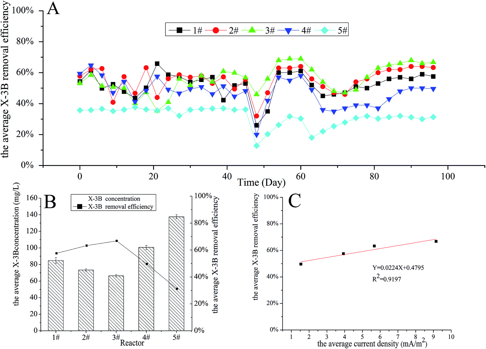 | ||
| Fig. 2 The removal efficiencies in four reactors with different cathode structures: (A) the average X-3B removal efficiencies from days 1 to 96; (B) the average X-3B removal efficiencies when the concentration of X-3B was 200 mg L−1; (C) the relationship between the average X-3B removal efficiency and the average current density. | ||
Fig. 2B shows that the average X-3B removal efficiency in the four different reactors was relatively stable when the concentration of X-3B was 200 mg L−1. It can be seen that the average concentrations of X-3B in the four different reactors were 84.90, 73.37, 66.42, and 100.72 mg L−1, respectively. The average X-3B removal efficiencies were 57.55%, 63.31%, 66.79%, and 49.64%, respectively. Liu20 et al. constructed a BER and found that the decolorization efficiency increased from 39.30 to 76.23% when the initial dye concentration decreased from 200 to 25 mg L−1. Zhang28 et al. also constructed a BER which got a 35.8% higher X-3B decolorization efficiency than the control group. Rahmani29 et al. constructed another BER with C.I. Acid Red 18 decolorization efficiency of 73.5% when the optimized current density was 8.6 mA cm−2. It can be concluded that the BER constructed in this study achieved the similar level of decolorization efficiency. Meanwhile, it was found that the average X-3B removal efficiency did not change with the total surface area of the cathode in the four reactors with different cathode structures. It is generally believed that the removal efficiency increases as the total surface area of a cathode increases; however, there was no direct link between the removal efficiency and the total surface area of the cathode in this experiment.
The currents in the four different reactors were measured over time. The average current densities were 3.93, 5.67, 9.16, and 1.54 mA m−2, respectively. As shown in Fig. 2C, there was a positive correlation (R2 = 0.9197) between the average X-3B removal efficiency and the average current density, with the removal efficiency rising as the current in the reactor increased. The internal resistances of the four different reactors were 839.56, 437.33, 381.90, and 1035.63 Ω, respectively, with these values obtained via polarization curves. It can be seen that the removal efficiency decreased with increasing internal resistance. In bioelectrochemical systems, the internal resistance composes by ohm internal resistance, mass transfer internal resistance and activation polarization internal resistance. Ohm resistance mainly comes from the electrode materials; mass transfer resistance mainly comes from transmission of reactants and products to the electrode surface and internal resistance due to activation polarization mainly comes from the activation energy which the electrochemical reactions require in cathode and anode. In our experiment, because the resistance of cathode and anode materials were small, ohm internal resistance was not the major influence factor which led to different internal resistance. Meanwhile, Wang30 et al. reported that higher current always accompanied by lower mass transfer resistance in microbial electrolysis cell. The current (less than 0.1 mA) in our study was low, so the mass transfer resistance was relatively high which had a relatively large impact on internal resistance. Moreover, Elmekawy31 et al. reported the internal resistance due to activation polarization could be change by changing the projected surface area of anodic and cathodic electrodes. The projected cathodic surface areas of the four reactors in our study were different, so were the activation polarization internal resistances. Thus, the different on mass transfer and the polarization resistance between four kinds of cathode construction led to different internal resistance. The removal of X-3B was a process that required electrons to be gained to reduce the action of microorganisms under anaerobic conditions. The increase in current density in the whole system meant that more electrons could be utilized for the reduction of X-3B, and the X-3B removal efficiency then increased. Therefore, the main factor influencing the X-3B removal efficiency in the reactors with different cathode structures was the different internal resistances caused by the different cathode constructions.
3.2 The removal efficiencies in the cathode filled with GAC-BERs
The influence of a cathode filled with GAC-BERs on the X-3B removal efficiency was studied. The concentration of X-3B was 100 mg L−1 at the beginning of the experiment, and reached 150 and 200 mg L−1 on days 46 and 60, respectively. As shown in Fig. 3A, the X-3B removal efficiency in a GAC-BER stabilized from days 30 to 96, while the removal efficiency in a BER was affected by the concentration of the influent from days 46 to 60. This was because, compared with ACF, the porous surface of GAC could provide more favorable conditions for microbial growth, which enables microorganisms to withstand the impact of changes in influent concentrations.32 | ||
| Fig. 3 The removal efficiencies in BER and the cathode filled with GAC-BER: (A) the average X-3B removal efficiencies from days 1 to 96; (B) the average COD and X-3B removal efficiencies when the concentration of X-3B was 200 mg L−1. | ||
Fig. 3B shows the average COD and X-3B removal efficiencies in BER and GAC-BER when the concentration of X-3B was 200 mg L−1. The COD removal efficiencies were 78.60% and 72.37%, and the X-3B removal efficiencies were 64.68% and 46.93%. The cathode filled with GAC-BER did not improve the COD removal efficiency, while the X-3B removal efficiency actually declined. When the cathode was filled with electrode material GAC, it was easy for short circuits in the current to reduce the current efficiency in the reactor, which led to fewer electrons being available for the reduction of X-3B and decreased the removal efficiencies as a consequence. The average maximum current densities in the two reactors were 9.16 and 1.02 mA m−2. It was clear that the current in the BER was higher than in the GAC-BER, and the removal efficiencies were also better.
3.3 The removal efficiencies in reactors with anodes composed of different materials and SEM results
The X-3B removal efficiency in reactors with anodes composed of different materials was investigated. The average COD and X-3B removal efficiencies in BER and DSA-BER are shown in Fig. 4A. It can be seen that the COD removal efficiencies were 78.60% and 86.54%, and the X-3B removal efficiencies were 64.68% and 75.70%. The COD and X-3B removal efficiencies were noticeably better in the DSA-BER than in the BER (P < 0.01). This may have been caused by the strong catalysis of the DSA electrode, prompted by strong oxidizing substances, such as hydroxyl radicals,33 which were formed at the anode and oxidized the X-3B. Alternatively, it may have been due to the DSA electrode, which would increase the current in the system and improve the removal efficiency.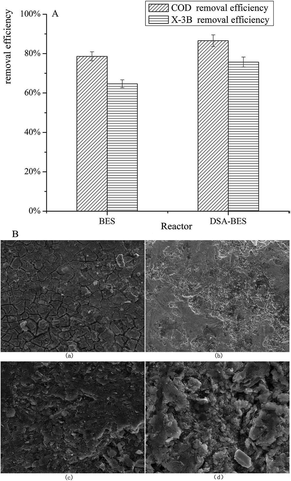 | ||
| Fig. 4 (A) The average COD and X-3B removal efficiencies in reactors with anodes composed of different materials; (B) SEM images of two different anodes before and after 120 days. | ||
The components of the influent were analyzed, with the strong oxidizing substances formed at the anode including ClO− and OH˙. The Cl− in NaCl and NH4Cl were first converted to Cl2 and then to ClO−. The standard oxidation potential for the conversion of Cl− to Cl2 was 1.358 V (vs. SHE), and the standard oxidation potential for the conversion of H2O to OH˙ was 2.8 V (vs. SHE). In this experiment, the DC power supply (1 V). The anode potential was 0.27 V measured by calomel electrode, and was 0.51 V when converted to hydrogen electrode reference (vs. SHE) which was much lower than the oxidation potential for ClO− and OH˙. Therefore, the strong oxidizing substances ClO− and OH˙ would not be formed.
The internal resistances of the two different anode reactors were 318.9 and 142.46 Ω, respectively, with the values obtained via polarization curves. The current in the BER was 0.412 mA, while in the DSA-BER it was 0.715 mA. The lower internal resistance of the DSA-BER resulted in a higher current density for the same DC power supply, which we considered to be the reason that the removal efficiencies were improved.
Fig. 4B shows SEM images of the two different anodes. Fig. 4B(a) and (b) are characterizations of the DSA anode before and after 120 days, and Fig. 4B(c) and (d) are characterizations of the graphite anode. By comparing (a) and (b) with (c) and (d), it was found that the surface of the DSA anode changed little, and was still smooth with good stability. We speculate that this may result in the DSA anode having a longer service life. Marshall et al.34 also reported a similar phenomenon. In contrast, the surface of the graphite anode was loose, broken, and uneven. Owing to long-term soaking, solution had penetrated into the center of the graphite rod, which may have been the cause of the increase in internal resistance.
3.4 UV-vis spectral analysis
Analysis by UV-vis spectroscopy was conducted to investigate the removal of X-3B. The UV-vis spectrum of the influent (X-3B 200 mg L−1) is shown in Fig. 5A. It shows six absorbance features, including 513 and 538 nm in the visible region, 235, 285, and 285 nm in the near UV region, and 198 nm in the far ultraviolet region. The wide absorbance feature that appeared at 513–540 nm was caused by the conjugate system n–π, which was formed by benzene, a naphthalene ring, and –NN–. The conjugate system makes X-3B present its unique red color. The absorbance feature at 198 nm was an oxygen peak, the absorbance feature at 235 nm represented a benzene ring, the absorbance feature at 285 nm corresponded to a naphthalene ring, and the peak at 332 nm represented triazinyl.35,36
 | ||
| Fig. 5 The UV-vis spectrum of (A) the influent (X-3B 200 mg L−1); (B) the influent and the effluent from the BER, GAC-BER, and DSA-BER. | ||
Fig. 5B shows the UV-vis spectrum of the effluent from the BER, GAC-BER, and DSA-BER as well as the influent. As shown in this figure, the conjugate system in the effluent of the three types of reactors was destroyed. There were no new absorbance features in the visible region (380–780 nm). The extent of the removal of the conjugate system in the DSA-BER and BER was better than in the GAC-BER, which was explained by the DSA-BER and BER having higher X-3B removal efficiency. The four absorbance features (198, 235, 285, and 332 nm) all disappeared at the same time. However, there were some new absorbance features between 240 and 265 nm, which implies that the azo dye degraded into lower-molecular-weight products. A continual treatment process is needed to degrade these breakdown substances.
4. Conclusions
A set of conditions for constructing a BER for azo dye degradation were obtained. The average X-3B removal efficiency reached 63.31% in the best cathode structural BER of the four reactors investigated here. The COD and X-3B removal efficiencies in the GAC-BER were 72.37% and 46.93%, which were both lower than in the BER. The cathode filled with the GAC-BER did not improve the COD removal efficiency, while the X-3B removal efficiency actually declined. The COD and X-3B removal efficiencies in the DSA-BER were 86.54% and 75.70%, which was a noticeable improvement compared with the BER. The DSA anode had a longer service life than the graphite anode. UV-vis spectral analysis revealed that the conjugate system in X-3B was destroyed. Furthermore, the optimization of the operating conditions (e.g., the voltage of the DC power supply, ionic strength, and temperature) are needed to increase the removal efficiency of azo dye.Acknowledgements
This work was supported by the National Natural Science Foundation of China (21277024); the Fundamental Research Funds for the Central Universities and Scientific Research Foundation of Graduate School of Southeast University.References
- Z. Fang, H. L. Song, C. Ning and X. N. Li, Bioresour. Technol., 2013, 144, 165–171 CrossRef CAS PubMed.
- A. Moutaouakkil, Y. Zeroual, F. Z. Dzayri, M. Talbi, K. Lee and M. Blaghen, Curr. Microbiol., 2004, 48, 124–129 CrossRef CAS PubMed.
- Z. B. Chen, M. H. Cui, N. Q. Ren, Z. Q. Chen, H. C. Wang and S. K. Nie, Bioresour. Technol., 2011, 102, 8839–8847 CrossRef CAS PubMed.
- M. H. Cui, C. Dan, H. S. Lee, B. Liang, A. J. Wang and H. Y. Cheng, Sci. Rep., 2016, 6, 25223 CrossRef CAS PubMed.
- Z. Li, X. Zhang, J. Lin, S. Han and L. Lei, Bioresour. Technol., 2010, 101, 4440–4445 CrossRef CAS PubMed.
- M. H. Vijaykumar, Y. Veeranagouda, K. Neelakanteshwar and T. B. Karegoudar, World J. Microbiol. Biotechnol., 2006, 22, 157–162 CrossRef CAS.
- D. Cui, Y. Q. Guo, H. S. Lee, H. Y. Cheng, B. Liang, F. Y. Kong, Y. Z. Wang, L. P. Huang, M. Y. Xu and A. J. Wang, Chem. Eng. J., 2014, 243, 355–363 CrossRef CAS.
- H. Y. Yang, C. S. He, L. Li, J. Zhang, J. Y. Shen, Y. Mu and H. Q. Yu, Sci. Rep., 2016, 6, 27243 CrossRef CAS PubMed.
- B. Liang, H.-Y. Cheng, D.-Y. Kong, S.-H. Gao, F. Sun, D. Cui, F.-Y. Kong, A.-J. Zhou, W.-Z. Liu and N.-Q. Ren, Environ. Sci. Technol., 2013, 47, 5353–5361 CrossRef CAS PubMed.
- D. Kong, B. Liang, H. Yun, H. Cheng, J. Ma, M. Cui, A. Wang and N. Ren, Water Res., 2015, 72, 281–292 CrossRef CAS PubMed.
- L. Huang, L. Jiang, Q. Wang, X. Quan, J. Yang and L. Chen, Chem. Eng. J., 2014, 253, 281–290 CrossRef CAS.
- H. Luo, G. Liu, R. Zhang, Y. Bai, S. Fu and Y. Hou, J. Hazard. Mater., 2014, 270, 153–159 CrossRef CAS PubMed.
- M. H. Cui, D. Cui, L. Gao, A. J. Wang and H. Y. Cheng, Water Res., 2016, 105, 520 CrossRef CAS PubMed.
- Y. Mu, K. Rabaey, R. A. Rozendal, Z. Yuan and J. Keller, Environ. Sci. Technol., 2009, 43, 5137–5143 CrossRef CAS PubMed.
- D. Cui, Y.-Q. Guo, H.-Y. Cheng, B. Liang, F.-Y. Kong, H.-S. Lee and A.-J. Wang, J. Hazard. Mater., 2012, 239, 257–264 CrossRef PubMed.
- M. Zhou, W. Wang and M. Chi, Bioresour. Technol., 2009, 100, 4662 CrossRef CAS PubMed.
- A. J. Wang, H. Y. Cheng, B. Liang, N. Q. Ren, D. Cui, N. Lin, B. H. Kim and K. Rabaey, Environ. Sci. Technol., 2017, 45, 10186–10193 CrossRef PubMed.
- F. Aulenta, A. Canosa, M. Majone, S. Panero, P. Reale and S. Rossetti, Tree Genet. Genomes, 2008, 4, 343–358 CrossRef.
- J. C. Thrash, J. I. Van Trump, K. A. Weber, E. Miller, L. A. Achenbach and J. D. Coates, Environ. Sci. Technol., 2007, 41, 1740–1746 CrossRef CAS PubMed.
- S. Liu, H. Song, S. Wei, Q. Liu, X. Li and X. Qian, Biochem. Eng. J., 2015, 93, 294–302 CrossRef CAS.
- S. Zhang, H. L. Song, X. L. Yang, K. Y. Yang and X. Y. Wang, Chemosphere, 2016, 164, 113 CrossRef CAS PubMed.
- F. Kong, A. Wang and H.-Y. Ren, Bioresour. Technol., 2014, 166, 252–258 CrossRef CAS PubMed.
- Q. Sun, Z.-L. Li, Y.-Z. Wang, C.-X. Yang, J. S. Chung and A.-J. Wang, Bioresour. Technol., 2016, 208, 64–72 CrossRef CAS PubMed.
- S. Zhou, J. Tang and Y. Yuan, Bioelectrochemistry, 2015, 102, 29–34 CrossRef CAS PubMed.
- Y. Zhou, Y.-F. Xia, W. Li and L. Gao, Environ. Sci. Technol., 2013, 47, 657 CrossRef CAS.
- X. Cao, H. Wang, X. Q. Li, Z. Fang and X. N. Li, Bioresour. Technol., 2016, 227, 273–278 CrossRef PubMed.
- S. Puig, M. Coma, J. Desloover, N. Boon, J. S. Colprim and M. D. Balaguer, Environ. Sci. Technol., 2012, 46, 2309–2315 CrossRef CAS PubMed.
- J. Zhang, Y. Zhang, X. Quan, S. Chen and S. Afzal, Bioresour. Technol., 2013, 136, 273–280 CrossRef CAS PubMed.
- A. R. Rahmani, K. Godini, D. Nematollahi, G. Azarian and S. Maleki, Korean J. Chem. Eng., 2016, 33, 532–538 CrossRef CAS.
- Q. Wang, H. Dong, H. Yu, H. Yu and M. Liu, RSC Adv., 2015, 5, 10346–10351 RSC.
- A. Elmekawy, H. M. Hegab, X. Dominguezbenetton and D. Pant, Bioresour. Technol., 2013, 142, 672–682 CrossRef CAS PubMed.
- A. Cardenas-Robles, E. Martinez, I. Rendon-Alcantar, C. Frontana and L. Gonzalez-Gutierrez, Bioresour. Technol., 2013, 127, 37–43 CrossRef CAS PubMed.
- E. Chatzisymeon, A. Dimou, D. Mantzavinos and A. Katsaounis, J. Hazard. Mater., 2009, 167, 268–274 CrossRef CAS PubMed.
- A. T. Marshall and R. G. Haverkamp, J. Mater. Sci., 2012, 47, 1135–1141 CrossRef CAS.
- X. Zhang, G. Li and Y. Wang, Dyes Pigm., 2007, 74, 536–544 CrossRef CAS.
- F. Wu, N. Deng and H. Hua, Chemosphere, 2000, 41, 1233–1238 CrossRef CAS.
| This journal is © The Royal Society of Chemistry 2017 |