DOI:
10.1039/C7RA00094D
(Paper)
RSC Adv., 2017,
7, 14678-14687
CO2 separation membranes with high permeability and CO2/N2 selectivity prepared by electrostatic self-assembly of polyethylenimine on reverse osmosis membranes†
Received
4th January 2017
, Accepted 27th February 2017
First published on 6th March 2017
Abstract
CO2 separation membranes prepared by green, simple, and efficient methods have faced great challenges. In this work, a facilitated transport membrane with high CO2 permeance and CO2/N2 selectivity was prepared by an aqueous self-assembly method using commercially available polyethylenimine (PEI) and reverse osmosis (RO) membranes as the assembled molecule and substrate, respectively. When the PEI concentration was 50 mg L−1, the prepared membranes showed excellent permeability and selectivity. The effects of PEI concentration, pH of electrostatic-assembly and operating conditions on the membrane performance were systemically studied. The prepared membrane was also analyzed by scanning electron microscopy (SEM), X-ray photoelectron spectroscopy (XPS) and contact angle measurements to determine the adsorption and assembly kinetics of PEI. For CO2, the facilitated transport mechanism was dominant because of the presence of amine groups from PEI molecules, while N2 transport was accomplished by a simple solution-diffusion mechanism.
1. Introduction
Separation and recycling of CO2 from post-combustion, pre-combustion and oxy-fuel combustion1,2 are vitally important for society. Combustion of fossil fuel can satisfy the increasing demands of energy that accompany rapid economic growth, but this process releases a significant amount of CO2, an important greenhouse gas responsible for approximately 60% of global warming.3 Worldwide CO2 emissions have nearly doubled since 1971.4 However, CO2 should be removed from fuel gases like methane, syngas and natural gas,5,6 thus enhancing their calorific value and reducing pipeline corrosion during transport. Recycled CO2 can be reused to produce ammonia, urea, refrigerants, and fire extinguishing gases, as well as to enhance the recovery of oil in oil/gas reservoirs and coal bed methane.7,8 Commercial CO2 separation technologies mainly include absorption, adsorption, cryogenic separation, and membrane separation. Among these technologies, membrane separation has received the most interest because this process is clean, simple, energy efficient, and low in cost.9–12
Types of CO2 separation membranes include polymeric membranes, sol–gel membranes and facilitated transport membranes. Traditional polymeric membranes have been widely used in commercial applications,13 but they are limited by their permeability–selectivity trade-off, known as Robeson's upper bound.14,15 Although sol–gel membranes have high permeability and high selectivity, they are difficult to apply in practice because of the instability and expense of ionic liquid,16 as well as solvent pollution. Facilitated transport membranes of the type described in this work could surpass the upper boundary for permeability and selectivity via reversible reactions of reactive carriers in the membranes and target gases,17 such as CO2. Carriers in facilitated transport membranes may be mobile or fixed; the former type may be subject to degradation of membrane permeance because of evaporation of the membrane solution or removal of the carriers by washing,6,18 while the latter type does not suffer from this limitation.
Generally, CO2 is an unreactive molecule, but it can react rapidly with amines at normal temperature and pressure to form carbamates. The reaction is essentially an acid–base equilibrium.19 When a fixed carrier membrane containing amine groups (primary amine or secondary amine) is swollen by a solvent (e.g. water) acting as a reaction medium, the facilitated transport mechanism of CO2 in the membrane is described by the following formula:20,21
| | |
2CO2 + 2RNH2 + H2O ⇄ RNHCOOH + RNH3+ + HCO3−
| (1) |
| | |
2CO2 + 2R2NH + H2O ⇄ R2NCOOH + R2NH2+ + HCO3−
| (2) |
Thus, CO2 in membranes is transported from one carrier site to another by free diffusion and carrier diffusion simultaneously. As a result of the reversible reactions described above, CO2 and its carriers are released at the lower pressure side.5
Several carriers with amino groups have been developed, including polyetherimide/polyvinylpyrrolidone (PVP),22 carboxymethyl chitosan/polyethylenimine (CMCS/PEI),17 polyethylenimine/poly(vinylalcohol) (PEI/PVA),18 amino-agarose derivative/polyethersulfone (AAG/PES),23 amine-containing polymer/zeolite Y/polyethersulfone (PES),24 high-molecular-weight polyvinylamine/piperazine glycinate (PVAm/PG),25 diethanolamine-impregnated poly(vinyl alcohol) (DEA/PVA).26 Most of these membranes were prepared by solution casting on supported layers, which results in mass solvent pollution. Moreover, each of these preparation methods required post-treatments, such as heat treatment or peeling the membranes from glass plates, making the preparation process very lengthy.
In this study, we used a polyelectrolyte self-assembly technique that was dependent on the electrostatic force between polycations and polyanions to form an ultrathin charged skin layer on the surface of commercial polyamide reverse osmosis membrane substrates. Using this relatively simple method, we successfully adjusted membrane thickness, charge density, and CO2 transport speed.27,28 The substrate membranes were prepared by interfacial polymerization of m-phenylenediamine with trimesoyl chloride on polysulfone porous substrates. The membranes were negatively charged under typical operating conditions (pH > 4) because of the presence of carboxyl groups on the membrane surface.29–32 Polyethylenimine (PEI) was chosen as the polycation in the membrane preparation process because it had the highest positive charge density among the materials available at the time of the study, as well as its abundant primary and secondary amino groups. The positive charge of PEI allows it to bond tightly to the negative membrane by electrostatic attraction, and its amino groups facilitate CO2 transport. The method described in this study, which utilizes electrostatic self-assembly of an ultra-low concentration of PEI in aqueous solution on polyamide membranes, is inexpensive, environmentally friendly, easy to perform, and rapid. In this work, we describe the effects of varying the PEI concentration, pH of the PEI solution, and preparation conditions (feed pressure and pump pressure) on the structure and performance of the facilitated transport membrane to determine the applicable self-assembly rules and appropriate conditions for membrane preparation.
2. Experimental
2.1. Materials
Commercial polyamide reverse osmosis composite membranes were obtained from the Development Center of Water Treatment Technology (Hangzhou, China). The membrane surface contained abundant carboxyl groups, as shown in Fig. 1(a). Branched PEI was purchased from Sigma-Aldrich (average molecular weight = 750![[thin space (1/6-em)]](https://www.rsc.org/images/entities/char_2009.gif) 000). The chemical structure of PEI is shown in Fig. 1(b). High purity nitrogen and CO2 feed gases were produced by Jingong Specialty Gases Inc. (Hangzhou, China). Hydrochloric acid (HCl, AR) was purchased from Huadong Medicine Inc. (Hangzhou, China). Deionized water with conductivity <3 μs cm−1 was used in this study. All chemicals were used without any further purification.
000). The chemical structure of PEI is shown in Fig. 1(b). High purity nitrogen and CO2 feed gases were produced by Jingong Specialty Gases Inc. (Hangzhou, China). Hydrochloric acid (HCl, AR) was purchased from Huadong Medicine Inc. (Hangzhou, China). Deionized water with conductivity <3 μs cm−1 was used in this study. All chemicals were used without any further purification.
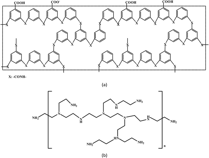 |
| | Fig. 1 Schematic diagrams of the chemical structures of the membrane surface (a) and polyethylenimine (b). | |
2.2. Membrane preparation
The immersion solutions were prepared by dissolving PEI in deionized water at predetermined concentrations (1–1000 mg L−1). The pH of each solution was adjusted to 5–11 by titration with dilute hydrochloric acid. The polyamide reverse osmosis membranes were cut into round shapes matching the test cell and supported by a porous, sintered, stainless steel plate fixed in the permeation cell. The effective permeation area of the membrane was 25 cm2. Before preparation, the membranes were tested under different pressures using high purity nitrogen and CO2 feed gases, thus obtaining the permeance and selectivity of the as-delivered membranes. Afterwards, the PEI solution was poured into a tank and circulated past the membrane surface by a pump for 1 hour. The pump provided transport pressure ranging from 0.1 to 1.1 MPa. Simultaneously, polycations were deposited on the negatively charged polyamide membrane surface. This preparation was carried out in situ (the membrane remained in the cell during the entire process), as a result the differences in the performances of the original and prepared membranes were clear. The prepared membranes were used for further permeation experiments.
2.3. Membrane characterization
The surface and cross section view of the membranes were examined by scanning electron microscopy (SEM) using a HitachiS-4700 instrument. The chemical composition of the prepared membranes near the membrane surface was characterized by X-ray photoelectron spectroscopy (XPS) using a Kratos AXIS Ultra DLD instrument. Contact angle measurements were carried out using a Dataphysics OCA 30 instrument to assess membrane surface wettability. A water drop was allowed to sit on the surface of the original and prepared membranes for 5 s to achieve complete wetting. Each sample was tested at five different points to reduce the chance of experimental error.
2.4. Permeation experiments
The original and prepared membranes were tested under feed gas pressures ranging from 0.1 to 0.5 MPa. Pure nitrogen was used first, followed by CO2. The flow rates of the permeation gases were measured by a soap bubble flowmeter. The pressure on the permeation side was atmospheric pressure. A schematic diagram of the permeation unit for CO2 and N2 separation is shown in Fig. 2(a). The feed gases were humidified with water vapor generated from a buffer tank, thus avoiding dehydration and maintaining the separation performance of the membrane in the test cell. The measured temperature (25 °C) was kept constant by a water-bath. The humidified feed gas and permeation gas go across the membrane in a countercurrent flow. The membrane preparation process is shown in Fig. 2(b). After preparation, the membrane was placed in the setup described above to test its performance (Fig. 2(a)).
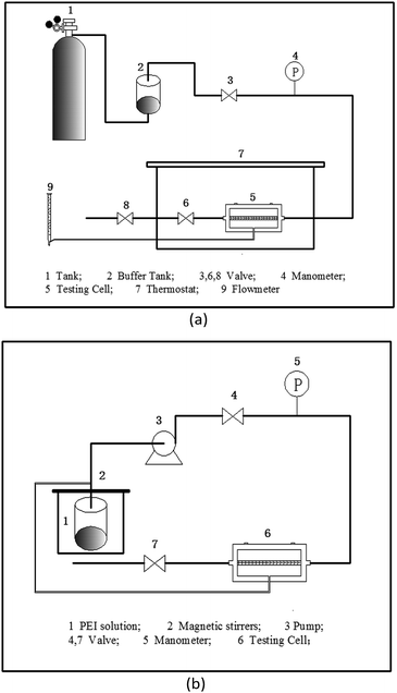 |
| | Fig. 2 Schematic diagram of the experimental setup for (a) CO2 and N2 permeation testing; (b) membrane preparation. | |
The separation performance of CO2 membranes is determined by solute permeability, solute permeance, and selectivity for the target species relative to other components in the feed stream.33,34 The permeability of species i (Pi) is represented by the following expression:
| |
 | (3) |
in this expression,
Pi is expressed in Barrer, which is equivalent to 10
−10 cm
3 (STP) cm (cm
2 s cmHg)
−1.
Pi/
l is the permeance of the membrane and is expressed in gas permeation units (GPU), which are equivalent to 10
−6 cm
3 (STP) (cm
2 s cmHg)
−1.
JTi is the total flux of species i, Δ
pi is the pressure difference of species i across the membrane, and
l is the effective thickness of the membrane. For asymmetric membranes,
l cannot be measured accurately; therefore, in these cases,
Pi/
l is generally taken into consideration rather than
Pi; as
l is reduced,
Pi increases. The selectivity of species i with the respect to species j (
αij) is defined as:
| |
 | (4) |
where
x and
y are the mole fraction of the gas on the feed and penetration side respectively. But if the penetration pressure is negligible compared to the feed pressure, the ideal selectivity can be represented as:
| |
 | (5) |
3. Results and discussion
3.1. SEM images
SEM was used to examine the surface and cross section morphologies of the membranes. As shown in Fig. 3, the images of membranes prepared at different PEI concentrations and pH values were studied. From the surface images of original and prepared membranes, it could be seen evidently that PEI molecules were self-assembled onto the membranes surface. But because the self-assembly layer was ultrathin, the thickness of the PEI coated layer on the membrane surface couldn't be measured by the cross section point of view (see Fig. 3(c)).
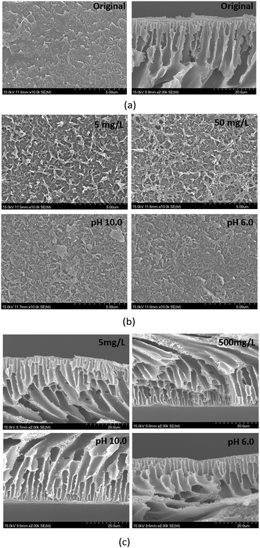 |
| | Fig. 3 SEM images of surface and cross section for membranes prepared by different PEI concentrations (pH = 8.0) and pH values (50 mg L−1) (a) original membranes; (b) surface morphologies; (c) cross section views. | |
3.2. XPS analysis
The thickness of the interfacially polymerized skin layer was approximately 100 nm. Fourier transform infrared (FT-IR) spectra of membranes was measured firstly, but due to the small number of PEI molecules self-assembled, the results couldn't be proved the functional groups on the skin layer of membranes (see FT-IR spectra in ESI†). The sample surface was probed to a depth of 1–10 nm by XPS, as a result the XPS analysis only considered the top layer near the membrane surface. The results of the analysis of C, O, and N are shown in Table 1. O was found in the basement membrane, where it was the result of hydrolysis of acyl chloride on the polyamide membrane surface. PEI contains only C and N, as a result the O/N ratio represents the amount of –COOH on the membrane surface. The theoretical O/N ratio of a fully crosslinked polyamide is 1;35 when the O/N ratio exceeds 1, the membrane surface is negatively charged. When the O/N ratio is less than 1, excessive PEI absorption occurs. In this study, when the PEI concentration was less than 400 mg L−1, the O/N ratio was greater than 1 (Table 1). When the PEI concentration was greater than 400 mg L−1, the O/N ratio was less than 1. In addition, the O/N ratio at a PEI concentration of 50 mg L−1 (pH 8.0) was slightly greater than 1, while the O/N ratio at a PEI concentration of 500 mg L−1 (pH 8.0) was slightly less than 1. At PEI concentrations of 50 mg L−1 and 500 mg L−1, the O/N ratio at pH 6 was greater than 1, while the O/N ratio at pH 10 was less than 1.
Table 1 XPS results for CO2 separation membranes prepared under different conditions
| PEI concentration/pH |
O/% |
N/% |
C/% |
O/N |
| PA RO membrane |
13.65 |
13.14 |
73.21 |
1.04 |
| 5 mg L−1 PEI, pH 8.0 |
14.56 |
13.05 |
72.39 |
1.12 |
| 50 mg L−1 PEI, pH 8.0 |
14.87 |
14.85 |
70.27 |
1.00 |
| 70 mg L−1 PEI, pH 8.0 |
14.98 |
13.89 |
71.13 |
1.08 |
| 100 mg L−1 PEI, pH 8.0 |
14.3 |
13.22 |
72.47 |
1.08 |
| 150 mg L−1 PEI, pH 8.0 |
14.16 |
13.95 |
71.89 |
1.02 |
| 400 mg L−1 PEI, pH 8.0 |
14.05 |
14.2 |
71.75 |
0.99 |
| 500 mg L−1 PEI, pH 8.0 |
15.14 |
15.15 |
69.71 |
1.00 |
| 700 mg L−1 PEI, pH 8.0 |
14.34 |
15.37 |
70.29 |
0.93 |
| 1000 mg L−1 PEI, pH 8.0 |
14.52 |
16.15 |
69.33 |
0.90 |
| 50 mg L−1 PEI, pH 6.0 |
14.43 |
12.54 |
73.03 |
1.15 |
| 50 mg L−1 PEI, pH 10.0 |
14.1 |
14.73 |
71.17 |
0.96 |
| 500 mg L−1 PEI, pH 6.0 |
14.42 |
14.15 |
71.43 |
1.02 |
| 500 mg L−1 PEI, pH 10.0 |
15.21 |
15.45 |
69.34 |
0.98 |
3.3. Contact angle measurements
For facilitated transport membranes, saturated water vapor molecules in feed gases can increase the reaction rate of CO2 with carriers (working like weak base catalysts, as shown in eqn (1) and (2)) and the water vapor molecules can also increase the driving force for CO2 transport to determine the permselective properties.5,36,37 Thus, hydrophilicity is a significant influence on the performance of facilitated transport membranes. The water drop contact angles for the membranes assessed in this study under different concentrations and pH levels are shown in Table 2. Even if the membrane is prepared with a very low concentration of PEI, the contact angle was sharply decreased in comparison with that of a PA RO membrane. That meant PEI molecules were self-assembled onto the membranes, thus increasing the membrane hydrophilicity. That was consistent with the results of SEM. In addition, the contact angle did not vary significantly (approximately 30° to 45°) across the range of PEI concentrations tested in this study. The contact angles for membranes with 50 mg L−1 PEI (pH 8.0) and 500 mg L−1 (pH 10.0) were less than 30°; therefore, these membranes had excellent hydrophilicity. The contact angles of the membranes decreased sharply as pH was increased. Taken together, these results showed that the hydrophilicity of the prepared membranes surpassed the hydrophilicity of the original membranes, while alkaline conditions favored membrane hydrophilicity in comparison with acidic conditions.
Table 2 Effects of PEI concentration and pH on membrane contact angle (0.4 MPa pump pressure and 25 °C operating temperature)
| PEI concentration/pH level |
Contact angle (°) |
| PA RO membrane |
61.7 ± 0.5 |
| 5 mg L−1 PEI, pH 8.0 |
47.0 ± 2.0 |
| 50 mg L−1 PEI, pH 8.0 |
24.4 ± 1.8 |
| 70 mg L−1 PEI, pH 8.0 |
38.2 ± 1.9 |
| 100 mg L−1 PEI, pH 8.0 |
41.7 ± 1.9 |
| 150 mg L−1 PEI, pH 8.0 |
34.3 ± 2.5 |
| 400 mg L−1 PEI, pH 8.0 |
31.1 ± 0.9 |
| 500 mg L−1 PEI, pH 8.0 |
47.4 ± 2.4 |
| 700 mg L−1 PEI, pH 8.0 |
43.4 ± 1.6 |
| 1000 mg L−1 PEI, pH 8.0 |
42.7 ± 1.0 |
| 50 mg L−1 PEI, pH 6.0 |
44.4 ± 3.3 |
| 50 mg L−1 PEI, pH 10.0 |
31.7 ± 7.0 |
| 500 mg L−1 PEI, pH 6.0 |
43.5 ± 2.6 |
| 500 mg L−1 PEI, pH 10.0 |
24.4 ± 0.8 |
3.4. Effect of feed pressure on membrane separation performance
The effect of gas feed pressure on membrane performance was studied at different PEI concentrations and pH levels. The feed pressure ranged from 0.1 MPa to 0.5 MPa. As shown in Fig. 4, the N2 and CO2 permeance of the original and prepared membranes increased as the feed pressure was increased. This change is contradictory to the commonly accepted idea that CO2 permeance decreases as feed pressure increases for normal facilitated transport membranes. In previous studies, decreased CO2 permeance was the result of carrier saturation on the feed side of the membrane under low pressure.5,18,38,39 Therefore, in this study, membrane carriers did not reach saturation at lower feed pressures, as a result transport was accomplished by solution-diffusion and facilitated transport mechanisms. In addition, the N2 and CO2 permeance of the prepared membranes was reduced in comparison with that of the original membranes, likely because additional PEI hydrogel layers on the membrane surface increased transport resistance. However, the CO2/N2 selectivity of the original membranes decreased as the feed pressure was increased, while that of the prepared membranes first increased and then plateaued at a constant level.
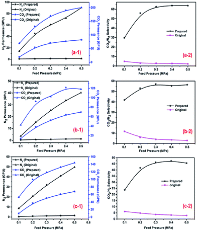 |
| | Fig. 4 Effect of feed pressure on CO2, N2 permeance and CO2/N2 selectivity (a-1), (a-2): 50 mg L−1, pH = 10.0; (b-1), (b-2): 30 mg L−1, pH = 8.0; (c-1), (c-2) 250 mg L−1, pH = 8.0. The operating temperature was 25 °C; the pump pressure was 0.4 MPa. (1 GPU = 1 × 10⁻⁶ cm3 (STP) cm2 s cmHg). | |
N2 did not react with the membrane carriers, and its flux changed in an approximately linear manner for the original and prepared membranes as the feed pressure was increased; however, the change in N2 permeance was insignificant for the prepared membranes, which indicated that N2 permeance was the result of solution-diffusion only. For humidified CO2, facilitated transport by PEI (and H2O) played a dominant role, as a result CO2 permeance and CO2/N2 selectivity increased as the feed pressure was increased from 0.1 to 0.3 MPa. However, when the feed pressure was greater than 0.3 MPa, the membranes carriers reached saturation, while the complexation reaction rate stabilized,38 thus decreasing CO2 permeance accordingly. Under these conditions, increasing feed pressure increased the driving force of transport and gas solubility, favoring the process of solution-diffusion. As a result of this change, CO2 permeance and CO2/N2 selectivity tended to plateau at constant levels.
3.5. Effect of PEI solution concentration on membrane separation performance
The effect of the PEI concentration on membrane performance was investigated (0.4 MPa pump pressure, 25 °C operating temperature, and pH 8). The feed pressure ranged from 0.1 MPa to 0.5 MPa. Feed pressures of 0.2 and 0.3 MPa were taken as examples. The PEI concentration ranged from 1 mg L−1 to 1000 mg L−1. In order to allow an explicit comparison of the performance of the prepared and original membranes, the values of gas permeance and CO2/N2 selectivity were normalized. In terms of self-assembly layers increasing transport resistance, the gas permeance of the prepared membranes was reduced in comparison with that of the original membranes, as a result the normalization values were less than 1. As shown in Fig. 5, N2 and CO2 permeance decreased first, after which it increased. At PEI concentrations of 150 mg L−1 or greater, CO2 permeance remained almost constant as the concentration was increased, while N2 permeance continued to increase. As a result, CO2/N2 selectivity increased first, after which it decreased.
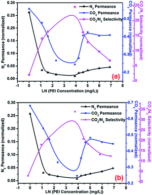 |
| | Fig. 5 Effect of PEI concentration on membrane performance under feed pressures of (a) 0.2 MPa; (b) 0.3 MPa. The permeance and CO2/N2 selectivity values of the prepared membranes were normalized to those of the original membranes. Operating conditions: pump pressure = 0.4 MPa, temperature = 25 °C. | |
In water-swollen polymer membranes, increased permeance of N2 and CO2 can be ascribed to the increased free volume between swollen polymer chains. Meanwhile, water molecules in the membrane act as an N2 barrier and facilitate CO2 transport.36 Therefore, increased free volume between polymer chains and facilitated transport by PEI and H2O are two important factors resulting in the performance changes observed in this study following membrane wetting. Under these conditions, the number of PEI molecules that assemble onto the membrane increases as the PEI concentration is increased. This change was illustrated by the results of XPS and contact angle analysis. Facilitated transport of CO2 by PEI and H2O was gradually enhanced as the PEI concentration was increased; consequently, the permeance rate of CO2 through the membrane was faster than that of N2, and CO2/N2 selectivity was increased. This change was consistent at PEI concentrations lower than 50 mg L−1. However, additional PEI molecules adsorbed onto the membranes at PEI concentrations of 50 mg L−1 and higher increased the free volume between PEI polymer chains, increasing permeance by CO2 and N2. Under these conditions, permeance was strongly influenced by the free volume between polymer chains. In addition, the increase in the free volume between polymer chains decreased the number of water molecules between polymer chains and was unfavourable to facilitated transport of CO2; therefore, N2 and CO2 permeance both increased, while CO2/N2 selectivity decreased. When the PEI concentration was higher than 150 mg L−1, CO2 permeance tended to be constant because of saturation of PEI adsorption, while N2 permeance continued to increase, as a result CO2/N2 selectivity continued to decrease.
3.6. Effect of PEI concentration and pH on membrane performance
The effect of the pH of the PEI solution on membrane separation performance was studied (0.4 MPa pump pressure and 25 °C operating temperature). The feed pressure ranged from 0.1 MPa to 0.5 MPa; a feed pressure of 0.1 MPa was taken as an example. Changes in separation performance at low (50 mg L−1) and high (500 mg L−1) PEI concentrations were assessed. As shown in Fig. 6(a) and (b), as pH was increased, permeance of CO2 and N2 decreased and then increased, while CO2/N2 selectivity increased and then decreased.
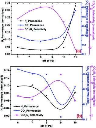 |
| | Fig. 6 Effect of PEI concentration and pH on gas permeance and CO2/N2 selectivity at PEI concentrations of (a) 50 mg L−1 and (b) 500 mg L−1. Operating temperature, 25 °C; feed pressure, 0.1 MPa; pump pressure, 0.4 MPa. | |
For this phenomenon, combined contributions from facilitated transport by PEI/H2O and increased free volume (ascribed to polymer swelling) are responsible for the changes in performance described above. Typically, alkaline solutions lead to deprotonation of carboxyl groups on membranes, creating a more negatively charged surface and favoring adsorption of PEI molecules. As shown by the results of XPS and contact angle analysis (Tables 1 and 2), pH influences to self-assembly of PEI molecules. At pH values lower than 8, the relative permeance rate of CO2 through membranes by PEI-facilitated transport becomes much faster than that of N2 as pH increases, as a result CO2/N2 selectivity increases. However, at pH values of 8 and higher, more PEI molecules self-assemble onto the membranes, increasing the free volume between swollen polymer chains and thus enhancing permeance. Under these conditions, increased free volume is the strongest influence on gas permeance; CO2 and N2 permeance increases, while CO2/N2 selectivity decreases. In addition, damage to the PA skin layer by alkaline solutions may cause gas leakage and decreased CO2/N2 selectivity. At pH values lower than 8, the area between PEI molecules is occupied by water molecules, which also contribute to facilitated transport of CO2.
3.7. Effect of self-assembly temperature on membrane performance
The effects of self-assembly temperature on membrane separation performance were studied at a PEI concentration of 500 mg L−1, a pump pressure of 0.4 MPa and a pH value of 9.0. A feed pressure of 0.1 MPa were taken as an example. The experimental results were shown herein in Table 3. As the self-assembly temperature was increased, the speed of PEI molecules transported to the membrane surface was accelerated. When additional PEI molecules adsorbed onto the membranes, the free volume between swollen polymer chains was increased and played a dominant role resulting in the membranes performance changes, thus enhancing permeance, while CO2/N2 selectivity decreased.
Table 3 Effect of self-assembly temperature on membrane separation performance
| Self-assembly temperature (°C) |
Permeance normalization |
Selectivity normalization |
| N2 |
CO2 |
CO2/N2 |
| 20 |
0.02 |
0.12 |
7.03 |
| 30 |
0.06 |
0.17 |
3.02 |
| 40 |
0.07 |
0.20 |
2.85 |
3.8. Effect of pump pressure on membrane performance
The effects of pump pressure on membrane separation performance were studied at a PEI concentration of 500 mg L−1, an operating temperature of 25 °C, and a pH value of 9.0. Feed pressures of 0.1 MPa and 0.2 MPa were taken as examples. As shown in Fig. 7(a) and (b), gas permeance decreased and then increased, while CO2/N2 selectivity increased and then decreased. As the self-assembly pump pressure was increased, additional PEI molecules were transported to the membrane surface per unit interval; this effect was similar to that caused by increasing the PEI concentration. Under a pump pressure of 0.6 MPa, facilitated transport of CO2 by PEI/H2O was gradually enhanced as additional PEI molecules assembled onto the membrane; as a result, the relative permeance of CO2 through the membrane was faster than that of N2, while CO2/N2 selectivity was increased. However, when the pump pressure was 0.6 MPa or higher, the increased free volume caused by polymer swelling played a dominant role, as a result N2 and CO2 permeance increased, while CO2/N2 selectivity decreased.
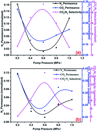 |
| | Fig. 7 Effect of pump pressure on membrane separation performance at feed pressures of (a) 0.1 MPa and (b) 0.2 MPa. Operating temperature, 25 °C; PEI concentration, 500 mg L−1; pH, 9. | |
3.9. Adsorption kinetics and equilibrium curves
The effect of PEI self-assembly time on membrane separation performance was investigated at an operating temperature of 25 °C, a PEI concentration of 50 mg L−1, and a pH value of 8.0. Feed pressures of 0.2 MPa and 0.3 MPa were taken as examples. As shown in Fig. 8(a) and (b), N2 and CO2 permeance both declined, after which they tended to remain unchanged as self-assembly time increased. As a result, CO2/N2 selectivity increased and then stayed constant. It is clear that contact between the membrane and PEI solution for a period of tens of seconds greatly changed the separation performance of the membrane. Under these conditions, additional PEI molecules were adsorbed onto the membrane as self-assembly time increased, which gradually enhanced facilitated transport. As a result of facilitated transport, the rate at which CO2 permeance decreased slowed; in comparison with N2 permeance, a longer time was required for CO2 permeance to plateau at a constant level. CO2 permeance was unchanged after the carrier sites reached saturation. Therefore, CO2/N2 selectivity increased first, after which it was constant.
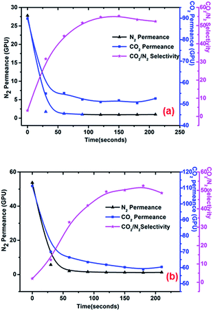 |
| | Fig. 8 Effect of self-assembly time on membrane separation performance under feed pressures of (a) 0.2 MPa and (b) 0.3 MPa. Operating temperature, 25 °C; PEI concentration, 50 mg L−1; pH, 8.0. | |
Although PEI adsorption can reach an equilibrium state in a very short time, reducing the time for PEI molecule self-assembly increases the risk of gas leakage, resulting in a sharp drop in CO2/N2 selectivity, especially under relatively high feed pressure. Therefore, 1 h was selected as the self-assembly time to guarantee complete self-assembly and stable performance.
4. Comparison of separation performance with that of other membranes
Table 4 shows the separation performance of the electrostatic self-assembly membranes obtained in this study and that of other membranes reported elsewhere. Membranes produced by self-assembly did not have distinct advantages over those produced by other methods. However, self-assembly produced membranes with performance similar to that of other membranes reported elsewhere using a very simple method that required a very dilute solution. The production of membranes with higher separation performance should be explored in future investigations.
Table 4 Comparison of the performance of the membranes obtained in this work with that of other membranesa
| Membrane |
Preparation |
Post-treatment |
Feed gas (v/v) |
CO2 permeance (GPU) or permeability |
CO2/N2 selectivity |
Δp(pCO2) (MPa) |
T (°C) |
Ref. |
| Δp, transmembrane pressure (MPa); pCO2, CO2 partial at feed gas side (MPa); T, operating temperature (°C) during permeation; PVA, poly(vinylalcohol); PEG, poly(ethyleneglycol); DNMDAm, 3,3′-diamino-N-methyldipropylamine; TMC, trimesoyl chloride; PS, polysulfone; TETA, triethyelenetetramine; PES, polyethersulfone; AF-MWNTs, amino-functionalized multi-walled carbon nanotubes; POS, polysiloxane; PSF, polysulfone; PVAm, polyvinylamine. |
| PVA/PEG/PEI |
Solution casting and solvent evaporation |
Dried in a vacuum oven at 50 °C for 12 h |
Pure CO2, pure N2 |
250 |
Max: 24 |
0.1 |
25 |
39 |
| DNMDAm-TMC/PS |
Interfacial polymerization |
Washed and heat-treated |
CO2/N2 20/80 |
173, 97 |
70, 56 |
0.1(0.02), 0.5(0.1) |
Room temperature |
42 |
| PVA/TETA |
Solution casting |
Dried at room temperature for at least 24 h |
Pure CO2, pure N2 |
Max: 6.9 |
Max:50 |
7.6 cmHg |
25 |
20 |
| PVAm-EDA/PS |
Solution casting |
Dried at least 24 h before peeling from the substrate |
CO2/N2 20/80 |
239, 169, 109 |
83, 81, 73 |
0.1(0.02), 0.6(0.12), 1.1(0.22) |
Room temperature |
41 |
| PVAm/zeolite Y/PES |
Vacuum-assisted dip-coating |
Dried in a fume hood at room temperature for overnight before testing |
CO2/N2 20/80 |
Max: 1100 |
At least 200 |
1.5 psig |
57 |
24 |
| AF-MWNTs/PVA-POS/PSF |
Solution casting |
Immediately dried by convective air flow at 150 °C for 20 min, followed by thermal curing in a muffle oven at 120 °C for 6 h |
CO2/H2/N2 20/40/40 20/20.2/59.8 |
224 bars, 957 bars |
139, 384 |
28 bar, 15 bar |
107 |
40 |
| PEI/polyamide |
Electrostatic self-assembly |
NO |
Pure CO2, pure N2 |
77 |
63 |
0.2 |
25 |
This work |
5. Conclusions
A CO2 facilitated transport membrane was prepared through electrostatic self-assembly of PEI on a polyamide RO membrane in an aqueous solution. The method was simple, environmentally friendly, and rapid (tens of seconds). The prepared membrane was used in permeation experiments without any post-treatment. The assembly of PEI switched the charge of the membrane surface from negative to positive and led to good CO2 permeance and CO2/N2 selectivity, which was ascribed to the facilitated transport mechanism. Although CO2/N2 permeance was decreased after PEI assembly, the CO2/N2 selectivity of the prepared membrane was increased remarkably. A PEI concentration of 50 mg L−1 achieved optimal permeance and selectivity within a pH range of 8–9, implying that production of such membranes could be scaled up easily. The adsorption kinetics at 25 °C demonstrated that self-assembly of PEI on the polyamide membranes progressed quickly. Electrostatic assembly of PEI onto the membrane substrate at low PEI concentrations was deduced to be a primary reason for the increased performance of the prepared membranes.
Acknowledgements
This work was supported by the National Basic Research Program of China (grant no: 2015CB655303), the National Major Research and Development Program of China (grant no: 2016YFC0401508) and the Open Research Fund Program of Collaborative Innovation Center of Membrane Separation and Water Treatment of Zhejiang Province (2016ZD02, 2016YB08).
Notes and references
- E. Favre, Chem. Eng. J., 2011, 171, 782–793 CrossRef CAS.
- T. C. Merkel, H. Lin, X. Wei and R. Baker, J. Membr. Sci., 2010, 359, 126–139 CrossRef CAS.
- R. Sabouni, H. Kazemian and S. Rohani, Environ. Sci. Pollut. Res. Int., 2014, 21, 5427–5449 CrossRef CAS PubMed.
- K. Oaman, C. Coquelet and D. Ramjugernath, S. Afr. J. Sci., 2014, 110, 12 Search PubMed.
- J. Zou and W. S. W. Ho, J. Membr. Sci., 2006, 286, 310–321 CrossRef CAS.
- Y. Zhang, J. Sunarso, S. Liu and R. Wang, Int. J. Greenhouse Gas Control, 2013, 12, 84–107 CrossRef CAS.
- D. Y. C. Leung, G. Caramanna and M. M. Maroto-Valer, Renewable Sustainable Energy Rev., 2014, 39, 426–443 CrossRef CAS.
- X. Wang, V. Alvarado, N. Swoboda-Colberg and J. P. Kaszuba, Energy Convers. Manage., 2013, 65, 564–573 CrossRef CAS.
- A. Brunetti, F. Scura, G. Barbieri and E. Drioli, J. Membr. Sci., 2010, 359, 115–125 CrossRef CAS.
- J. K. Adewole, A. L. Ahmad, S. Ismail and C. P. Leo, Int. J. Greenhouse Gas Control, 2013, 17, 46–65 CrossRef CAS.
- Z. Dai, R. D. Noble, D. L. Gin, X. Zhang and L. Deng, J. Membr. Sci., 2016, 497, 1–20 CrossRef CAS.
- C. A. Scholes, K. H. Smith, S. E. Kentish and G. W. Stevens, Int. J. Greenhouse Gas Control, 2010, 4, 739–755 CrossRef CAS.
- W. F. Yong, F. Y. Li, Y. C. Xiao, T. S. Chung and Y. W. Tong, J. Membr. Sci., 2013, 443, 156–169 CrossRef CAS.
- K. Friess, J. C. Jansen, F. Bazzarelli, P. Izák, V. Jarmarová, M. Kačírková, J. Schauer, G. Clarizia and P. Bernardo, J. Membr. Sci., 2012, 415–416, 801–809 CrossRef CAS.
- D. Bastani, N. Esmaeili and M. Asadollahi, J. Ind. Eng. Chem., 2013, 19, 375–393 CrossRef CAS.
- M. Hasib-ur-Rahman, M. Siaj and F. Larachi, Chem. Eng. Process., 2010, 49, 313–322 CrossRef CAS.
- J. N. Shen, C. C. Yu, G. N. Zeng and B. van der Bruggen, Int. J. Mol. Sci., 2013, 14, 3621–3638 CrossRef CAS PubMed.
- H. Matsuyama, A. Terada, T. Nakagawara, Y. Kitamura and M. Teramoto, J. Membr. Sci., 1999, 163, 221–227 CrossRef CAS.
- E. M. Hampe and D. M. Rudkevich, Tetrahedron, 2003, 59, 9619–9625 CrossRef CAS.
- A. Uma Maheswari and K. Palanivelu, Can. J. Chem., 2017, 95, 57–67 CrossRef.
- Y. Wang, Y. Shang, X. Li, T. Tian, L. Gao and L. Jiang, Polymers, 2014, 6, 1403–1413 CrossRef CAS.
- W. N. W. Salleh and A. F. Ismail, AIChE J., 2012, 58, 3167–3175 CrossRef CAS.
- F. Seidi, M. B. Salarabadi, S. Saedi, L. Modadi, A. A. Shamsabadi and B. Nikravesh, Greenhouse Gases: Sci. Technol., 2015, 5, 701–713 CrossRef CAS.
- Y. Chen, L. Zhao, B. Wang, P. Dutta and W. S. Winston Ho, J. Membr. Sci., 2016, 497, 21–28 CrossRef CAS.
- Y. Chen and W. S. W. Ho, J. Membr. Sci., 2016, 514, 376–384 CrossRef CAS.
- G. J. Francisco, A. Chakma and X. Feng, Sep. Purif. Technol., 2010, 71, 205–213 CrossRef CAS.
- J. Xu, X. Feng and C. Gao, J. Membr. Sci., 2011, 370, 116–123 CrossRef CAS.
- Z. Zhu, X. Feng and A. Penlidis, Mater. Sci. Eng., C, 2007, 27, 612–619 CrossRef CAS.
- Y. Zhou, S. Yu, C. Gao and X. Feng, Sep. Purif. Technol., 2009, 66, 287–294 CrossRef CAS.
- Q. Li, Z. Xu and I. Pinnau, J. Membr. Sci., 2007, 290, 173–181 CrossRef CAS.
- D. Saeki, T. Tanimoto and H. Matsuyama, Colloids Surf., A, 2014, 443, 171–176 CrossRef CAS.
- S. S. Shenvi, A. M. Isloor and A. F. Ismail, Desalination, 2015, 368, 10–26 CrossRef CAS.
- L. A. El-Azzami and E. A. Grulke, J. Membr. Sci., 2008, 323, 225–234 CrossRef CAS.
- D. F. Sanders, Z. P. Smith, R. Guo, L. M. Robeson, J. E. McGrath, D. R. Paul and B. D. Freeman, Polymer, 2013, 54, 4729–4761 CrossRef CAS.
- Y. Zhou, Z. Dai, D. Zhai and C. Gao, Chin. J. Chem. Eng., 2015, 23, 912–918 CrossRef CAS.
- Y. Li, Q. Xin, S. Wang, Z. Tian, H. Wu, Y. Liu and Z. Jiang, Chem. Commun., 2015, 51, 1901–1904 RSC.
- Y. Li, Q. Xin, H. Wu, R. Guo, Z. Tian, Y. Liu, S. Wang, G. He, F. Pan and Z. Jiang, Energy Environ. Sci., 2014, 7, 1489 CAS.
- S. Andrew Lee, G. W. Stevens and S. E. Kentish, J. Membr. Sci., 2013, 429, 349–354 CrossRef CAS.
- S. Ben Hamouda, Q. T. Nguyen, D. Langevin and S. Roudesli, C. R. Chim., 2010, 13, 372–379 CrossRef CAS.
- L. Ansaloni, Y. Zhao, B. T. Jung, K. Ramasubramanian, M. G. Baschetti and W. S. W. Ho, J. Membr. Sci., 2015, 490, 18–28 CrossRef CAS.
- S. Yuan, Z. Wang, Z. Qiao, M. Wang, J. Wang and S. Wang, J. Membr. Sci., 2011, 378, 425–437 CrossRef CAS.
- X. Yu, Z. Wang, Z. Wei, S. Yuan, J. Zhao, J. Wang and S. Wang, J. Membr. Sci., 2010, 362, 265–278 CrossRef CAS.
Footnote |
| † Electronic supplementary information (ESI) available. See DOI: 10.1039/c7ra00094d |
|
| This journal is © The Royal Society of Chemistry 2017 |
Click here to see how this site uses Cookies. View our privacy policy here.  Open Access Article
 a,
Xueting Zhaoa,
Yong Zhou*a and
Congjie Gaoab
![[thin space (1/6-em)]](https://www.rsc.org/images/entities/char_2009.gif) 000). The chemical structure of PEI is shown in Fig. 1(b). High purity nitrogen and CO2 feed gases were produced by Jingong Specialty Gases Inc. (Hangzhou, China). Hydrochloric acid (HCl, AR) was purchased from Huadong Medicine Inc. (Hangzhou, China). Deionized water with conductivity <3 μs cm−1 was used in this study. All chemicals were used without any further purification.
000). The chemical structure of PEI is shown in Fig. 1(b). High purity nitrogen and CO2 feed gases were produced by Jingong Specialty Gases Inc. (Hangzhou, China). Hydrochloric acid (HCl, AR) was purchased from Huadong Medicine Inc. (Hangzhou, China). Deionized water with conductivity <3 μs cm−1 was used in this study. All chemicals were used without any further purification.


