 Open Access Article
Manganese dioxide nanowires on carbon nanofiber frameworks for efficient electrochemical device electrodes†
Y. Saito a,
M. Meguroa,
M. Ashizawaa,
K. Wakib,
R. Yukselc,
H. E. Unaland and
H. Matsumoto
 *a
*a
aDepartment of Materials Science and Engineering, Tokyo Institute of Technology, 2-12-1 Ookayama, Meguro-ku, Tokyo 152-8552, Japan. E-mail: matsumoto.h.ac@m.titech.ac.jp
bDepartment of Chemical Science and Engineering, Tokyo Institute of Technology, 4259, Nagatsuta-cho, Midori-ku, Yokohama-shi 226-8502, Japan
cDepartment of Micro and Nanotechnology, Middle East Technical University, Ankara 06800, Turkey
dDepartment of Metallurgical and Materials Engineering, Middle East Technical University, 06800 Ankara, Turkey
First published on 21st February 2017
Abstract
Hierarchically nanostructured composite electrodes were prepared by the electrodeposition of manganese dioxide nanowires (MnO2 NWs) with 5–20 nm diameters on electrospun carbon nanofiber (CNF) webs with diameters of 250 and 650 nm. The effects of CNF diameters and mass loading of MnO2 NWs on the hierarchical nanostructure formation and the performance of the composite electrodes were investigated. The internal structure of the composite electrode depended on CNF diameter and mass loading of MnO2 NW. The electrodes based on thinner CNFs and higher mass loadings of MnO2 NWs showed higher values of gravimetric and volumetric capacitances. This would be due to MnO2 NWs forming a dense network in the thinner three-dimensional CNF framework. In addition, asymmetric supercapacitors with the MnO2 NW/CNF composite electrode as the positive electrode and activated carbon as the negative electrode showed high energy and power densities of 8.9 W h kg−1 and 4.9 kW kg−1, respectively. These results clearly indicate that the hierarchical network nanostructure composed of an active material and a charge collector can be considered a promising electrode for various electrochemical devices.
Introduction
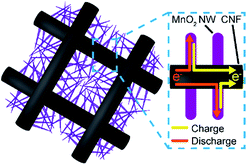
To improve the capacity of electrochemical supercapacitors, a wide range of metal oxides such as ruthenium oxide (RuO2),1,2 manganese dioxide (MnO2),3 vanadium oxide (V2O5),4 and nickel oxide (NiO)5 have been investigated as the active electrode materials and show promising characteristics. Among them, MnO2 with its high theoretical specific capacitance (1370 F g−1), natural abundance and environmental friendliness, as well as low cost, has received considerable attention.6 However, it is known that MnO2 shows a high specific capacitance only at very low loadings (about a few μg cm−2) on the current collector due to its extremely low electrical conductivity (10−5 to 10−6 S cm−1).3,6–8 Therefore, the development of high specific capacitance electrodes with MnO2 is still a challenge. To overcome this issue, many approaches, such as doping of MnO2,9 nanofabrication of MnO2,10 and composite formation using conductive materials11,12 have been taken. In particular, formation of composite electrodes using nanostructured MnO2 and conductive carbonaceous materials have attracted much attention.13–16 For example, several researchers reported MnO2 electrodes mixed with carbon microfibers,17 carbon nanotubes (CNT),18,19 graphene20–22 and a CNT/graphene complex.23,24Herein, we fabricated hierarchically nanostructured composite electrodes, MnO2 nanowires (MnO2 NWs) on carbon nanofiber (CNF) webs. The hierarchical nanostructure allows efficient charge collection through the three-dimensional (3-D) CNF framework (Fig. 1). Therefore, it is expected that this composite electrodes can simultaneously achieve high capacitance and rapid charge and discharge due to the high mass loading of the MnO2 NWs on the conductive CNF webs with high surface area. In the present study, MnO2 NW/CNF composite electrodes were prepared by the electrodeposition of MnO2 NWs with various mass loadings on the electrospun CNFs with diameters of 250 and 650 nm. We investigated the effects of CNF diameters and mass loadings of MnO2 NWs on the hierarchical nanostructure formation and the performance of the composite electrodes. In addition, we fabricated asymmetric supercapacitor (ASC) devices with the MnO2 NW/CNF composite electrode as the positive electrode and activated carbon (AC) as the negative electrode and evaluated their performance.
Experimental procedure
Materials
Polyacrylonitrile (PAN, Mw = 150![[thin space (1/6-em)]](https://www.rsc.org/images/entities/char_2009.gif) 000) was purchased from Sigma-Aldrich, USA. N,N-Dimethylformamide (DMF) of extra-pure grade and manganese(II) acetate tetrahydrate ((CH3COO)2Mn·4H2O)) of extra-pure grade were obtained from Wako Pure Chemical Industries, Japan. Sodium sulfate of extra-pure grade and hydrochloric acid of extrapure grade were obtained from Kanto Chemical, Japan. These reagents were used without further purification. Activated carbon sheet (AC sheet, the specific capacitance is 82.2 F g−1 at 1.0 A g−1) was obtained from Nippon Valqua Industries, Japan.
000) was purchased from Sigma-Aldrich, USA. N,N-Dimethylformamide (DMF) of extra-pure grade and manganese(II) acetate tetrahydrate ((CH3COO)2Mn·4H2O)) of extra-pure grade were obtained from Wako Pure Chemical Industries, Japan. Sodium sulfate of extra-pure grade and hydrochloric acid of extrapure grade were obtained from Kanto Chemical, Japan. These reagents were used without further purification. Activated carbon sheet (AC sheet, the specific capacitance is 82.2 F g−1 at 1.0 A g−1) was obtained from Nippon Valqua Industries, Japan.
Preparation of CNF webs
The CNF webs were prepared by electrospinning of a precursor polymer solution and successive stabilization and carbonization.25–27 Polyacrylonitrile (PAN) was used as the carbon precursor.28 For preparation of the spinning solution, PAN was dissolved in DMF to give 10 and 15 wt% PAN/DMF solutions. The electrospinning device was the same as that used in our previous study.29 The polymer solution was contained in a syringe with a stainless steel nozzle (0.21 mm internal diameter). The nozzle was connected to a high-voltage regulated DC power supply (HJPQ-30P1, Matsusada Precision, Japan). A constant volume flow rate was maintained by a syringe-type infusion pump (MCIP-III, Minato Concept, Japan). An aluminum plate (10 × 10 cm2) was used as the collector for the electrospun fibers. The distance between the nozzle tip and the collector were 10 and 15 cm for the 10 and 15 wt% solutions, respectively. The applied voltage was 8 kV, and the flow rate was 5 μL min−1. All spinnings were carried out at 25 ± 3 °C and at a relative humidity value of less than 60%. The as-spun PAN nanofibers were heated at 230 °C for 3 h in air for stabilizing, then they were heated at 1000 °C for 1 h in a nitrogen atmosphere for carbonization.Preparation of MnO2 NW/CNF composite electrodes
The MnO2 NW/CNF composite electrodes were prepared by electrodeposition of the MnO2 NWs onto the CNF surfaces. Before the deposition, the CNF webs were sufficiently washed with acetone (Ac) and deionized water (DIW) to remove any contaminants. Subsequently, the CNF webs were soaked in a 0.1 M hydrochloric acid solution for 10 min for the surface modification with hydrophilic groups, washed thoroughly by DIW, then dried at 100 °C for 3 h under vacuum. Before electrodeposition, the CNF webs were cut into small pieces (1 cm × 2 cm) and the cut samples were immersed overnight in the mixed solution of Ac and DIW (Ac![[thin space (1/6-em)]](https://www.rsc.org/images/entities/char_2009.gif) :
:![[thin space (1/6-em)]](https://www.rsc.org/images/entities/char_2009.gif) DIW = 1
DIW = 1![[thin space (1/6-em)]](https://www.rsc.org/images/entities/char_2009.gif) :
:![[thin space (1/6-em)]](https://www.rsc.org/images/entities/char_2009.gif) 1 v/v) in order to promote infiltration of the electrodeposition solution. MnO2 NWs were then deposited through the application of a constant voltage of 0.4 V (vs. Ag/AgCl sat.) in a solution containing 0.1 M (CH3COO)2Mn·4H2O and 0.1 M sodium sulfate (Na2SO4) at room temperature. The electrodepositions were carried out in a three-electrode cell with the CNF web as the working electrode, platinum mesh as the counter electrode, and a saturated Ag/AgCl electrode (DKK-TOA, Japan) as the reference electrode. The mass loading of the MnO2 NWs was controlled by the charge passed at the range of 0.22, 0.55, 2.1 and 4.2 C cm−2. After the deposition, the electrodes were removed from the electrodeposition solution and carefully washed with DIW to remove any excess electrolyte, then dried at 100 °C for 3 h under vacuum.
1 v/v) in order to promote infiltration of the electrodeposition solution. MnO2 NWs were then deposited through the application of a constant voltage of 0.4 V (vs. Ag/AgCl sat.) in a solution containing 0.1 M (CH3COO)2Mn·4H2O and 0.1 M sodium sulfate (Na2SO4) at room temperature. The electrodepositions were carried out in a three-electrode cell with the CNF web as the working electrode, platinum mesh as the counter electrode, and a saturated Ag/AgCl electrode (DKK-TOA, Japan) as the reference electrode. The mass loading of the MnO2 NWs was controlled by the charge passed at the range of 0.22, 0.55, 2.1 and 4.2 C cm−2. After the deposition, the electrodes were removed from the electrodeposition solution and carefully washed with DIW to remove any excess electrolyte, then dried at 100 °C for 3 h under vacuum.
Characterization
The electrical conductivities along the surface direction of the CNF webs were measured by a four-point probe method using a low resistivity meter (Loresta-GP MCP-T610, Mitsubishi Chemical Analytech, Japan). The morphological characterization of the prepared composite electrodes were made by a field-emission scanning electron microscope (FE-SEM, S4700, Hitachi, Japan), a scanning electron microscope (SEM, JCM-5700, JEOL, Japan), and a transmission electron microscope (TEM, JEM-2010F, JEOL, Japan) operated at 100 kV. The pore size distribution of the MnO2 NW/CNF composite electrodes was determined by mercury porosimetry measurements using an instrument (Auto Pore IV 9520, Micrometrics, USA). The crystal structure of the MnO2 NWs was determined by an X-ray diffractometer (XRD, X'Pert-MPD, Philips, Netherlands). X-ray photoelectron spectroscopy (XPS) was conducted by an instrument (JPS-9010MC, JEOL, Japan) equipped with a monochromator using an Al anode (12 kV, 25 mA). The acquired spectra were charge-corrected using the Mn 2p(3/2) signal at 642.0 eV.Electrochemical measurements
The electrochemical measurements of the MnO2 NW/CNF composite electrodes were carried out using a potentiostat/galvanostat (SI 1287, Solartron ISA, UK), and a frequency response analyzer (1255B, Solartoron ISA, UK). The electrochemical characteristics of the prepared MnO2 NW/CNF composite electrodes were determined by galvanostatic charge/discharge measurements in a three-electrode cell for plate-type electrodes (ALS, Japan). The composite electrode was used as the working electrode, platinum wire as the counter electrode, the Ag/AgCl electrode (3 M sodium chloride, NaCl) as the reference electrode, and a 1 M Na2SO4 solution as the electrolyte. Prior to the measurements, the composite electrode was soaked in the mixed solution of Ac and DIW (Ac![[thin space (1/6-em)]](https://www.rsc.org/images/entities/char_2009.gif) :
:![[thin space (1/6-em)]](https://www.rsc.org/images/entities/char_2009.gif) DIW = 1
DIW = 1![[thin space (1/6-em)]](https://www.rsc.org/images/entities/char_2009.gif) :
:![[thin space (1/6-em)]](https://www.rsc.org/images/entities/char_2009.gif) 1 v/v) for 1 h, then soaked overnight in a 1 M Na2SO4 solution.
1 v/v) for 1 h, then soaked overnight in a 1 M Na2SO4 solution.
Fabrication and evaluation of the asymmetric supercapacitor devices
The ASC devices were fabricated using a two-electrode cell (Hosen, Japan) with the MnO2 NW/CNF composite electrode as the positive electrode, an AC sheet as the negative electrode, Whatman cellulose filter as the separator between the two electrodes and a 1 M Na2SO4 solution as the electrolyte.Results and discussion
Preparation and characterization of CNF webs and MnO2 NW/CNF composite electrodes
The CNF webs with average diameters (D) of 256 ± 24 nm (C-250) and 667 ± 33 nm (C-650) were prepared by electrospinning from the 10 and 15 wt% PAN/DMF solutions, respectively, followed by successive carbonization (Fig. S1† shows SEM images of the prepared CNF webs and their diameter distribution). Thicknesses of the prepared webs were approximately 30 μm. C-250 and C-650 showed comparable apparent surface electric conductivities of 7.5 and 6.2 S cm−1, respectively (Table S1†).30MnO2 NWs with the mass loading of 0.10, 0.25, 0.95, and 1.9 mg cm−2 were successfully deposited onto the CNF webs by changing the charge amounts based on eqn (1). Hereafter, the prepared electrodes will be referred as Mn(-mass loading)/C(-CNF diameter) (e.g., Mn-0.10/C-250).
| Mn2+ + 2H2O → MnO2 + 4H+ + 2e− | (1) |
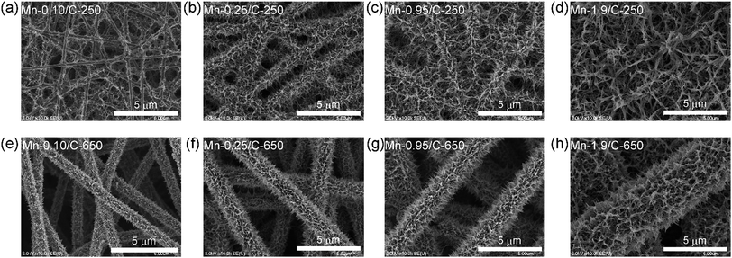
Fig. 2 shows SEM images of the MnO2 NW/CNF composite electrodes with various mass loadings. For the Mn/C-250s, MnO2 NWs mainly grew on the intersection points of CNF framework at the small mass loading of 0.10 mg cm−2 (Fig. 2(a)). With an increase in the mass loading, MnO2 NWs covered the surface of the CNFs and formed a layer structure (@0.25 mg cm−2, Fig. 2(b)). Finally, MnO2 NWs were densely grown and formed a network structure in the inter-fiber space of the CNF framework (@0.95 and 1.9 mg cm−2, Fig. 2(c) and (d), respectively): hierarchical network nanostructures composed of an active material and a charge collector was formed. On the other hand, for the Mn/C-650s (Fig. 2(e–h)), MnO2 NW did not form a network structure, but formed a thick layer on the surface of CNF at the higher mass loading (Table 1). The difference in the hierarchical structure between Mn/C-250s and Mn/C-650s is due to the differences in the surface area and the size of inter-fiber space between CNF frameworks.
| Specific mass loading (mg cm−2) | Thickness of MnO2 NW layera (μm) | MnO2 content (wt%) | ||
|---|---|---|---|---|
| C-250 | C-650 | C-250 | C-650 | |
| a The thickness of the MnO2 NW layer was determined from SEM analysis on average of 50 points. The MnO2 NW layer thickness of Mn/C-250s at 0.10, 0.95 and 1.9 mg cm−2 could not be determined, because MnO2 NWs were partially deposited on the CNF surface at 0.10 mg cm−2 and MnO2 NWs formed network structure in the inter-fiber space of the CNF framework. | ||||
| 0.10 | — | 0.16 ± 0.06 | 46.5 | 20.8 |
| 0.25 | 0.17 ± 0.03 | 0.98 ± 0.15 | 59.3 | 59.1 |
| 0.95 | — | 1.26 ± 0.15 | 81.0 | 77.9 |
| 1.9 | — | 2.02 ± 0.24 | 84.7 | 86.3 |
The TEM images demonstrate that MnO2 NWs grown on all the electrodes have high aspect ratios (several hundred nanometers in length and 5–20 nm in diameter). The MnO2 NWs were composed of aggregations of needle-like fine crystals with individual diameters of 2–5 nm (Fig. 3(a) and (b)). To identify the crystal structure of the MnO2 NWs, a large amount of MnO2 NWs (3.7 mg cm−2) were deposited onto C-250 electrode. The XRD patterns of the Mn-3.7/C-250 and C-250 are provided in Fig. 3(c). Peak positions of ramsdellite phase are provided in the same figure for comparison. There are two characteristic peaks around 37 and 65 degrees for Mn-3.7/C-250, which corresponds to the (021) and (061) planes of ramsdellite, but the other ramsdellite peaks are very weak and cannot be clearly observed. Chabre and some other researchers reported that the electrochemically-prepared MnO2 preferentially grows perpendicular to the (021) and (061) planes with a large concentration of structural defects called microtwinning.31–33 The chemical defects of microtwinning are known to be compensated by OH−/O2− in twinned boundaries.
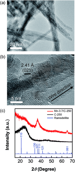 | ||
| Fig. 3 (a) TEM image of MnO2 NWs on Mn-0.95/C-250 electrode. (b) Higher magnification image of (a). (c) XRD patterns of Mn-3.7/C-250 electrode, C-250, and ramsdellite (ICDD: 042-1316). | ||
XPS results also indicate the existence of a large amount of structural water in the MnO2 NWs as discussed in ESI (Table S2 and Fig. S2†).31 In addition, the continuous twinning of the crystal phase was clearly observed in the deposited MnO2 NWs through high-magnification TEM analysis (Fig. 3(b)). This also supports the fact that the axis of MnO2 NWs would correspond either to the direction (021) or (061), and MnO2 NWs contain a number of twin boundaries.
Electrochemical measurements of MnO2 NW/CNF composite electrodes
Fig. 4(a) and (b) show the charge–discharge curves of Mn/C-250s and Mn/C-650s with various mass loadings at a current density of 0.5 A g−1, respectively. All the MnO2 NW/CNF composite electrodes show triangular curves: the larger amount of MnO2 NW-deposited electrode shows a smaller slope than unmodified CNF electrodes, demonstrating better capacitance.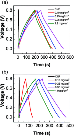 | ||
| Fig. 4 Charge–discharge curves of (a) Mn/C-250 and (b) Mn/C-650 composite electrodes with various mass loadings at a current density of 0.5 A g−1. | ||
The specific gravimetric capacitance for total electrode mass (Cg) and deposited MnO2 NWs (Cg-MnO2), and the specific volumetric capacitance for apparent volume of electrode (Cv) (the definitions are included in the ESI†) were evaluated by galvanostatic charge/discharge measurements as shown in Table 2. The Mn-0.95/C-250 electrode showed the highest Cg of 165 F g−1, which is better than the reported Cg of 120–150 F g−1 for the MnO2/carbon composite electrodes including MnO2 nanofiber/carbon nanosphere, MnO2 nanoparticle/CNT, and MnO2 nanoflower/graphene electrodes.16,34,35 Mn/C-250s show higher gravimetric and volumetric capacitances than those of Mn/C-650s at all the mass loadings. In addition, Mn/C-250s and Mn/C-650s show the maximum value of Cg and Cv at the mass loading of 0.95 mg cm−2. This can be explained by the assumption that the electrochemically utilizations of MnO2 NWs were substantially decreased at the mass loading of 1.9 mg cm−2 due to its small electric conductivities. The assumption was supported by a relatively large decrease in Cg-MnO2 at the greater mass loading of MnO2.
| Specific mass loading (mg cm−2) | Cg (F g−1) | Cv (F cm−3) | Cg-MnO2 (F g−1) | |||
|---|---|---|---|---|---|---|
| C-250 | C-650 | C-250 | C-650 | C-250 | C-650 | |
| 0.10 | 124 | 43.4 | 18.7 | 10.6 | 266 | 209 |
| 0.25 | 134 | 123 | 48.1 | 24.7 | 227 | 208 |
| 0.95 | 165 | 146 | 74.7 | 44.5 | 204 | 188 |
| 1.9 | 125 | 109 | 52.4 | 28.3 | 148 | 127 |
The difference in the capacitances between Mn/C-250s and Mn/C-650s more significantly appeared in volumetric capacitance than in gravimetric one. It would be due to the contribution of the internal structure of the MnO2 NW/CNF composite electrodes. To further investigate the structure–capacitance relationship of the MnO2 NW/CNF composite electrodes, the internal structural characteristics of the Mn-0.95/C-250 and the Mn-0.95/C-650 are summarized in Table 3 (pore size distribution is also shown in Fig. 5(a)). For the Mn-0.95/C-250, only a large number of nanosized pores, which correspond to the interspace between the MnO2 NWs, appeared. For the Mn-0.95/C-650, on the other hand, both a small number of nanosized pores and a large number of microsized pores, which correspond to the interspaces between the MnO2 NWs and surface-modified CNFs, respectively, appeared. As shown in Table 3, after electrodeposition of MnO2 NWs, the pore size of the C-250 decreased from 0.83 μm to 0.12 μm while that of C-650 was slightly increased from 2.69 μm to 2.72 μm. In addition, the porosity of the C-250 significantly decreased by the electrodeposition of MnO2 NWs, but that of C-650 was slightly increased from 57% to 63% as well as pore size (the MnO2 NW layer deposited on C-650 framework enlarge the inter-fiber space. This behaviour was also confirmed by the thickness change of the electrodes, see Fig. S3†). These internal structural changes are due to the difference in the hierarchical nanostructure between Mn/C-250 and Mn/C-650 composite electrodes: for the Mn-0.95/C-250, the MnO2 NWs form a network nanostructure in the CNF framework because of its narrow inter-fiber space.
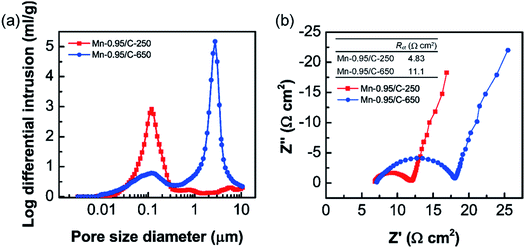 | ||
| Fig. 5 (a) Pore size distributions of Mn-0.95/C-250 and Mn-0.95/C-650 electrodes in the range from 3.0 nm to 10 μm. (b) Nyquist plots of Mn-0.95/C-250 and Mn-0.95/C-650 electrodes. | ||
Based on these structural characteristics, the findings that Mn-0.95/C-250 showed higher capacitance than Mn-0.95/C-650 could be explained by the following assumptions. At the high mass loading of Mn/C-250, formation of more densely network structure of MnO2 NWs in the CNF framework would enhance electrochemically utilization efficiency of MnO2 (Fig. 6(a)). On the contrary, at the high mass loading of Mn/C-650, the thick MnO2 NW layer with small electric conductivities6,32 would reduce electrochemically utilization efficiency of MnO2 (Fig. 6(b)). This is also supported by electrochemical impedance measurements: the charge transfer resistances (Rct) of the Mn-0.95/C-250 is lower than half of that of the Mn-0.95/C-650 (Fig. 5(b)).
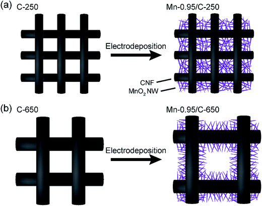 | ||
| Fig. 6 (a and b) Schematics of the internal structures of the CNF electrodes before and after electrochemical deposition of MnO2 NWs for C-250 and C-650, respectively. | ||
Fabrication and evaluation of the asymmetric supercapacitor
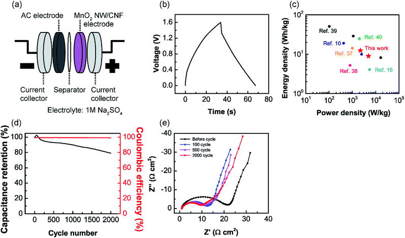
To confirm an applicability of the MnO2 NW/CNF composite electrodes for the supercapacitor electrode, an ASC device was fabricated and the device performance was evaluated. The device configuration is schematically shown in Fig. 7(a). Mn-0.95/C-250 electrode, AC, and 1 M Na2SO4 solution were used as the positive electrode, the negative electrode and the electrolyte, respectively. As shown in Fig. 7(b), the ASC operated at a voltage window of 1.6 V and achieved a capacitance of 25.1 F g−1 at a current density of 1.0 A g−1. This result compares with the previous works: MnO2 nanopowder and AC electrodes (22 F g−1 at 1.1 A g−1), MnO2 nanofiber/carbon nanosphere and carbon nanosphere electrodes (24.5 F g−1 at 1.0 A g−1), and MnO2 nanopowder and graphene electrodes (about 27 F g−1 at 1.0 A g−1).16,36,37 The energy and power densities (the definitions are included in the ESI†) of the ASC showed high values of 8.9 W h kg−1 and 4.9 kW kg−1 at 1.0 A g−1, respectively. For comparison with other ASCs prepared with MnO2 and carbonaceous materials, the Ragone plot is shown in Fig. 7(c).10,16,37–40 Fig. 7(d) shows the cyclic performance and coulombic efficiency of the ASC at a current density of 1.0 A g−1. This device showed a capacitance retention of 80% and high coulombic efficiency (>99%) after 2000 cycles. The decrease in capacitance would derive from the morphological change in the MnO2 NWs on the positive electrode because the AC negative electrode have good cycle stability (>97% after 2000 cycles). Fig. S4† shows the SEM image of Mn-0.95/C-250 electrode after 2000 cycles. The as-prepared MnO2 NWs were converted into a film-like structure at the electrolyte interface. Nyquist plots of the ASC during cycling test at a current density of 1.0 A g−1 are shown in Fig. 7(e). After 500 cycles, a new constant inclination (45° angle) region clearly appears in low-frequency range. The appearance of this region indicates the increase in diffusion length of ions and support the morphological change in the MnO2 NWs.41,42 This morphological change would be caused by slow dissolution and re-deposition of MnO2 during the electrochemical oxidation/reduction cycles and lead to a decrease in both the effective surface area and electric conductivities of the MnO2. For the practical use of the MnO2 NW/CNF composite electrodes, it will be a crucial issue to prevent the morphological change during the electrochemical oxidation/reduction cycles. Pang pointed out that the structural water in MnO2 decrease the cycle stability.3 As mentioned above MnO2 NWs contain a large number of structural water. A thermal treatment is a possible approach to improve the cycling stability.Conclusions
In the present study, hierarchically nanostructured composite electrodes were prepared by the electrodeposition of MnO2 NWs on the electrospun CNF webs and the structure–property relationship of the MnO2 NW/CNF composite electrodes was investigated. The internal structure of the composite electrodes depended on CNF diameter (or inter-fiber space of CNF framework) and loading amount of MnO2 NWs: at a large mass loading of MnO2, the deposited MnO2 NWs form a network nanostructure between the interconnected C-250 framework, while a thicker MnO2 NW layer was formed on the CNF surface in the C-650 framework. The electrodes based on the hierarchical structure composed of CNF framework and MnO2 NW network showed high gravimetric and volumetric capacitances. An asymmetric supercapacitor shows high energy and power densities of 8.9 W h kg−1 and 4.9 kW kg−1, respectively, and 80% capacitance retention and high coulombic efficiency (>99%) over 2000 cycles. This result clearly suggests hierarchical network nanostructure composed of an active material and a charge collector enhance the electrochemically utilization efficiency of MnO2 on the electrode surface. These findings provide a useful guide in design of efficient electrochemical device electrodes including supercapacitors.Acknowledgements
This study was partly supported by the fund for the Development of Human Resources in Science and Technology of the Japan Science and Technology Agency, JST (for H. M.) and a Grant-in-Aid for JSPS Research Fellows (No. 15J12492) by JSPS KAKENHI (for Y. S.). The authors appreciate the kind support of Mr Jun Koki, Mr Akira Genseki, and Mr Hiroshi Iida, Center for Advanced Materials Analysis, Tokyo Institute of Technology, for the SEM observations, TEM observations, and XRD measurements, respectively; and Dr Yuta Nabae, Department of Materials Science and Engineering, Tokyo Institute of Technology, for the XPS measurements.References
- D. Galizzioli, F. Tantardini and S. Trasatti, J. Appl. Electrochem., 1974, 4, 57–67 CrossRef CAS.
- S. Trasatti and G. Buzzanca, J. Electroanal. Chem. Interfacial Electrochem., 1971, 29, A1–A5 CrossRef.
- S. Pang, M. A. Anderson and T. W. Chapman, J. Electrochem. Soc., 2000, 147, 444–450 CrossRef CAS.
- H. Y. Lee and J. B. Goodenough, J. Solid State Chem., 1999, 148, 81–84 CrossRef CAS.
- V. Srinivasan and J. W. Weidner, J. Electrochem. Soc., 1997, 144, L210–L213 CrossRef CAS.
- M. Toupin, T. Brousse and D. Bélanger, Chem. Mater., 2004, 16, 3184–3190 CrossRef CAS.
- J. N. Broughton and M. J. Brett, Electrochim. Acta, 2005, 50, 4814–4819 CrossRef CAS.
- C. Xu, F. Kang, B. Li and H. Du, J. Mater. Res., 2010, 25, 1421–1432 CrossRef CAS.
- J. Kang, A. Hirata, L. Kang, X. Zhang, Y. Hou, L. Chen, C. Li, T. Fujita, K. Akagi and M. Chen, Angew. Chem., Int. Ed., 2013, 52, 1664–1667 CrossRef CAS PubMed.
- M. Huang, Y. Zhang, F. Li, L. Zhang, R. S. Ruoff, Z. Wen and Q. Liu, Sci. Rep., 2014, 4, 3878 Search PubMed.
- Q. Tang, M. Chen, C. Yang, W. Wang, H. Bao and G. Wang, ACS Appl. Mater. Interfaces, 2015, 7, 15303–15313 CAS.
- T. G. Yun, B. il Hwang, D. Kim, S. Hyun and S. M. Han, ACS Appl. Mater. Interfaces, 2015, 7, 9228–9234 CAS.
- T. Zhai, F. Wang, M. Yu, S. Xie, C. Liang, C. Li, F. Xiao, R. Tang, Q. Wu, X. Lu and Y. Tong, Nanoscale, 2013, 5, 6790–6796 RSC.
- G. Yu, L. Hu, M. Vosgueritchian, H. Wang, X. Xie, J. R. McDonough, X. Cui, Y. Cui and Z. Bao, Nano Lett., 2011, 11, 2905–2911 CrossRef CAS PubMed.
- J. Liu, J. Essner and J. Li, Chem. Mater., 2010, 22, 5022–5030 CrossRef CAS.
- Z. Lei, J. Zhang and X. S. Zhao, J. Mater. Chem., 2012, 22, 153–160 RSC.
- M.-S. Wu, Z.-S. Guo and J.-J. Jow, J. Phys. Chem. C, 2010, 114, 21861–21867 CAS.
- L. Hu, W. Chen, X. Xie, N. Liu, Y. Yang, H. Wu, Y. Yao, M. Pasta, H. N. Alshareef and Y. Cui, ACS Nano, 2011, 5, 8904–8913 CrossRef CAS PubMed.
- P. Li, Y. Yang, E. Shi, Q. Shen, Y. Shang, S. Wu, J. Wei, K. Wang, H. Zhu, Q. Yuan, A. Cao and D. Wu, ACS Appl. Mater. Interfaces, 2014, 6, 5228–5234 CAS.
- M. Yang, K. G. Lee, S. J. Lee, S. B. Lee, Y.-K. Han and B. G. Choi, ACS Appl. Mater. Interfaces, 2015, 7, 22364–22371 CAS.
- J. Deng, X. Wang, X. Duan and P. Liu, ACS Sustainable Chem. Eng., 2015, 3, 1330–1338 CrossRef CAS.
- B. Shen, J. Lang, R. Guo, X. Zhang and X. Yan, ACS Appl. Mater. Interfaces, 2015, 7, 25378–25389 CAS.
- Y. Cheng, S. Lu, H. Zhang, C. V. Varanasi and J. Liu, Nano Lett., 2012, 12, 4206–4211 CrossRef CAS PubMed.
- Y. Jin, H. Chen, M. Chen, N. Liu and Q. Li, ACS Appl. Mater. Interfaces, 2013, 5, 3408–3416 CAS.
- A. Greiner and J. H. Wendorff, Angew. Chem., Int. Ed., 2007, 46, 5670–5703 CrossRef CAS PubMed.
- D. Li and Y. Xia, Adv. Mater., 2004, 16, 1151–1170 CrossRef CAS.
- D. H. Reneker and A. L. Yarin, Polymer, 2008, 49, 2387–2425 CrossRef CAS.
- A. Krueger, Carbon Materials and Nanotechnology, Wiley-VCH Verlag GmbH & Co. KGaA, Weinheim, Germany, 2010 Search PubMed.
- H. Matsumoto, S. Imaizumi, Y. Konosu, M. Ashizawa, M. Minagawa, A. Tanioka, W. Lu and J. M. Tour, ACS Appl. Mater. Interfaces, 2013, 5, 6225–6231 CAS.
- S. Imaizumi, H. Matsumoto, K. Suzuki, M. Minagawa, M. Kimura and A. Tanioka, Polym. J., 2009, 41, 1124–1128 CrossRef CAS.
- Y. Chabre and J. Pannetier, Prog. Solid State Chem., 1995, 23, 1–130 CrossRef CAS.
- P. Ruetschi, J. Electrochem. Soc., 1984, 131, 2737–2744 CrossRef CAS.
- P. Ruetschi and R. Giovanoli, J. Electrochem. Soc., 1988, 135, 2663–2669 CrossRef CAS.
- M. Narubayashi, Z. Chen, K. Hasegawa and S. Noda, RSC Adv., 2016, 6, 41496–41505 RSC.
- Y. He, W. Chen, X. Li, Z. Zhang, J. Fu, C. Zhao and E. Xie, ACS Nano, 2013, 174–182 CrossRef PubMed.
- T. Brousse, M. Toupin and D. Bélanger, J. Electrochem. Soc., 2004, 151, A614–A622 CrossRef CAS.
- A. Mery, F. Ghamouss, C. Autret, D. Farhat and F. Tran-Van, J. Power Sources, 2016, 305, 37–45 CrossRef CAS.
- Y. S. Wang, D. S. Tsai, W. H. Chung, Y. S. Syu and Y. S. Huang, Electrochim. Acta, 2012, 68, 95–102 CrossRef CAS.
- Z. Fan, J. Yan, T. Wei, L. Zhi, G. Ning, T. Li and F. Wei, Adv. Funct. Mater., 2011, 21, 2366–2375 CrossRef CAS.
- P. Shang, J. Zhang, W. Tang, Q. Xu and S. Guo, Adv. Funct. Mater., 2016, 26, 7766–7774 CrossRef CAS.
- W. Sugimoto, H. Iwata, K. Yokoshima, Y. Murakami and Y. Takasu, J. Phys. Chem. B, 2005, 109, 7330–7338 CrossRef CAS PubMed.
- S.-E. Chun, S.-I. Pyun and G.-J. Lee, Electrochim. Acta, 2006, 51, 6479–6486 CrossRef CAS.
Footnote |
| † Electronic supplementary information (ESI) available. See DOI: 10.1039/c6ra28789a |
| This journal is © The Royal Society of Chemistry 2017 |

