 Open Access Article
Creative Commons Attribution 3.0 Unported Licence
Improved compatibility of DDAB-functionalized graphene oxide with a conjugated polymer by isocyanate treatment
Fei Zhenga,
Xiao-Yu Yanga,
Peng-Qing Bia,
Meng-Si Niua,
Cheng-Kun Lva,
Lin Fenga,
Xiao-Tao Hao *ab and
Kenneth P. Ghiggino
 b
b
aSchool of Physics and State Key Lab of Crystal Materials, Shandong University, Jinan 250100, China. E-mail: haoxt@sdu.edu.cn
bARC Centre of Excellence in Exciton Science, School of Chemistry, The University of Melbourne, Parkville, Victoria 3010, Australia
First published on 21st March 2017
Abstract
2-Chlorophenyl isocyanate (CI) reacts with didodecyl dimethyl ammonium bromide (DDAB) functionalized graphene oxide (DDAB-GO) dispersed in ortho-dichlorobenzene under mild conditions. The CI treatment complements DDAB functionalization to further decrease the hydrophilicity of pristine GO sheets. The resulting CI–DDAB-GO exhibits improved compatibility with the conjugated polymer poly(3-hexylthiophene) (P3HT), compared to DDAB-GO. CI–DDAB-GO sheets can be homogeneously dispersed when blended with P3HT, resulting in an improved morphology compared to P3HT:DDAB-GO composites. The incorporation of CI–DDAB-GO can effectively reduce the dark current of photo-diodes based on P3HT composites, showing potential to enhance the performance of electronic devices based on conjugated polymer composites.
Introduction
Graphene oxide (GO) is a 2-D carbon material that exhibits good solution processibility and is available at relatively low cost.1,2 It can be readily dispersed in water owing to its hydrophilic nature provided by oxygen containing groups, i.e. epoxy and hydroxyl in the basal plane, carbonyl and carboxyl at the edge.3 It has been widely reported that the incorporation of GO into polymers can produce composite materials with improved optical,4 electrical,5 and gas/water barrier properties.6 However, the hydrophilic nature of GO hampers its dispersion in common solvents except water, seriously limiting the preparation of polymer:GO composites. Fortunately, the oxygen-containing groups in GO provide reaction sites for both non-covalent and covalent functionalization by grafting oleophilic groups,7 rendering GO dispersible in organic solvents.Isocyanate functionalization has been a well adopted route for the covalent modification of GO proposed by Stankovich et al. in 2006.8 They treated GO powder suspended in anhydrous N,N-dimethylformamide (DMF) with a variety of isocyanates, such as phenyl isocyanate, tert-butyl isocyanate and p-acetylphenyl isocyanate. Isocyanate treated GO (iGO) can be easily exfoliated in polar organic solvents such as DMF, N-methylpyrrolidone (NMP) and dimethyl sulfoxide (DMSO). However, as reported, iGO cannot be dispersed in non-polar solvents, and this limits its applications where non-polar solvents are required.9
Previously, we have succeeded in the synthesis of didodecyl dimethyl ammonium bromide (DDAB) functionalized GO (DDAB-GO), which can be well dispersed in ortho-dichlorobenzene (DCB), by using an ionic functionalization pathway.10 As widely reported, the compatibility between GO and polymers plays a crucial role in determining the mechanical, electrical and thermal properties of the polymer:GO composites.11–13 Despite possessing good dispersibility in nonpolar solvents, DDAB-GO has poor compatibility with an added polymer phase. Cast films of a polymer or polymer blend that includes DDAB-GO invariably have poor morphologies, which in turn adversely affect performance and limits applications.14 Thus, there is a need to improve the compatibility of functionalized GO sheets with polymers in order to enhance the performance and applications of materials based on GO–polymer composites.
In this work, we combined two functionalization strategies for GO by treating DDAB-GO dispersed in DCB with 2-chlorophenyl isocyanate (CI). The resulting CI treated DDAB-GO, denoted as CI–DDAB-GO, exhibits nonpolar solvent dispersibility and improved compatibility with the conjugated polymer, poly(3-hexylthiophene) (P3HT). Photodiode devices based on the resulting conjugated polymer composite show improved performance.
Experimental section
Materials
Graphite oxide powder purchased from XFNANO Material Technologic Co. Ltd. (Nanjing, China) was synthesized by Hummers' method as reported by the manufacturer. Didodecyl dimethyl ammonium bromide (DDAB) and 2-chlorophenyl isocyanate (CI) were purchased from Aladdin Industrial Corporation (Shanghai, China). P3HT was purchased from Sigma-Aldrich Corporation (USA). All solvents including ethanol, DCB, hexane from Aladdin Corp. are of ACS grade purity and used as received without further purification.Preparation of DDAB-GO and CI–DDAB-GO
A graphene oxide aqueous dispersion (1 mg ml−1) was prepared by dispersing the required amount of graphite oxide powder into deionized water followed by ultrasound sonication (200 W) for 5 hours in a water bath with the temperature kept below 35 °C. 5 ml of the brown GO aqueous dispersion was loaded into a 30 ml glass bottle, after which 5 ml DDAB solution (1 mg ml−1) dissolved in water/ethanol (1![[thin space (1/6-em)]](https://www.rsc.org/images/entities/char_2009.gif) :
:![[thin space (1/6-em)]](https://www.rsc.org/images/entities/char_2009.gif) 1) was added with shaking to accomplish the ionic functionalization of GO by DDAB, leading to the coagulation of DDAB-GO. 5 ml DCB was added to the resulting suspension followed by simple shaking and then allowed to stand for a few minutes to obtain phase separation with DCB in the bottom and water/ethanol mixture as the supernate. After the removal of the supernate, 5 ml ethanol and water were sequentially added to the resulting DCB dispersion with magnetic stirring for 6 hours to extract out the excess DDAB. This purification process was repeated three times to obtain purified dispersions of DDAB-GO in DCB with a concentration of 1 mg ml−1. 2 ml DDAB-GO (DCB) dispersion was coagulated by adding 2 ml n-hexane and centrifuged at 5000 rpm for 30 min to collect the precipitate. The precipitate composed of DDAB-GO was dried in an oven and re-dispersed into DCB by simple ultrasound sonication, producing DDAB-GO dispersions of the required concentration.
1) was added with shaking to accomplish the ionic functionalization of GO by DDAB, leading to the coagulation of DDAB-GO. 5 ml DCB was added to the resulting suspension followed by simple shaking and then allowed to stand for a few minutes to obtain phase separation with DCB in the bottom and water/ethanol mixture as the supernate. After the removal of the supernate, 5 ml ethanol and water were sequentially added to the resulting DCB dispersion with magnetic stirring for 6 hours to extract out the excess DDAB. This purification process was repeated three times to obtain purified dispersions of DDAB-GO in DCB with a concentration of 1 mg ml−1. 2 ml DDAB-GO (DCB) dispersion was coagulated by adding 2 ml n-hexane and centrifuged at 5000 rpm for 30 min to collect the precipitate. The precipitate composed of DDAB-GO was dried in an oven and re-dispersed into DCB by simple ultrasound sonication, producing DDAB-GO dispersions of the required concentration.
400 μl 2-chlorophenyl isocyanate (CI) was added to a 2 ml DDAB-GO (DCB) dispersion (1 mg ml−1) followed by magnetic stirring for 12 hours at room temperature. The reaction product was coagulated by adding 2 ml n-hexane and collected as a precipitate after centrifugation at 3000 rpm for 30 minutes. The precipitate was re-dispersed into 2 ml fresh DCB with a few minutes of ultrasound sonication and subsequently centrifuged at 3000 rpm for 10 min, discarding the white sediment. The dark brown supernate was allowed to precipitate by adding 2 ml n-hexane and centrifuged at 5000 rpm for 30 min to collect the precipitate. This procedure was repeated 3 times to debride any residual CI or other wastes. Finally, the precipitate composed of CI–DDAB-GO was dried in an oven and re-dispersed into DCB by simple ultrasound sonication to provide CI–DDAB-GO dispersions of the required concentration.
20 mg ml−1 P3HT in DCB was mixed with 2 mg ml−1 DDAB-GO and CI–DDAB-GO DCB dispersions in a volume ratio of 1![[thin space (1/6-em)]](https://www.rsc.org/images/entities/char_2009.gif) :
:![[thin space (1/6-em)]](https://www.rsc.org/images/entities/char_2009.gif) 1 to form P3HT
1 to form P3HT![[thin space (1/6-em)]](https://www.rsc.org/images/entities/char_2009.gif) :
:![[thin space (1/6-em)]](https://www.rsc.org/images/entities/char_2009.gif) (10 wt%) GO composite solutions. Films of these composites were prepared by spin-casting at 600 rpm for 45 s on various substrates in a N2 filled glove box.
(10 wt%) GO composite solutions. Films of these composites were prepared by spin-casting at 600 rpm for 45 s on various substrates in a N2 filled glove box.
General characterization
Atomic Force Microscopy (AFM) images of DDAB-GO and CI–DDAB-GO sheets deposited on Si substrates from the diluted dispersions and P3HT:GO blend films deposited on glass substrates were obtained using a Multimode Scanning Probe Microscope (NanoScope-IIIA, Veeco Metrology Group) operating in tapping mode. The optical microscopy images of films are obtained using a microscope (Olympus) combined with CCD detector. X-ray photoelectron spectroscopy (XPS) measurements of GO and rGO were obtained using a X-ray Photoelectron Spectrometer (Escalab-250, Thermo Electron Co.). The UV-vis spectra of GO samples drop-cast on quartz substrates and polymer composite films spin-cast on glass substrates were obtained using a UV-visible dual-beam spectrophotometer (TU-1900, PG Instruments Co., Ltd.). The steady state photoluminescence (PL) spectra of the films were collected by a fiber optic spectrometer (PG2000-Prn, Morpho Inc.) after excitation by a 532 nm laser. The time resolved photoluminescence decay profiles of the composite thin films were obtained by using the time-correlated single-photon counting (TCSPC) technique. The excitation wavelength of 400 nm was generated by frequency doubling the output of Ti:sapphire laser (Mai Tai HP, Spectra-Physics) at 80 MHz. The power of the laser was set at 0.2 mW. The PL data were collected by a Halcyone spectrometer (Ultrafast Systems). The data were fitted using Gaussian and exponential convolution methods.9,10Grazing incidence wide angle X-ray scattering
Grazing incidence wide angle X-ray scattering (GIWAXS) measurements of polymer composite films spin-cast on silicon substrates were conducted at the Shanghai Synchrotron Radiation Facility (SSRF) using the BL16B1 beamline with a photon wavelength of 0.124 nm. The incidence angle of the X-ray is set to be 0.12°. The scattering intensity was detected by a CCD detector (MAR-165) with a pixel size of 80 μm. The distance between the sample center and detector is 240 mm. The 2-D image analysis was performed using the software Fit2d.Photoconductivity measurements
To measure the photoconductivity of the P3HT based composite films, photodiode devices with the structure of organic polymer solar cells (i.e. ITO (glass)/ZnO (40 nm)/composite film/MoO3 (8 nm)/Ag (100 nm)) were fabricated. ZnO films used as the electron transporting layer were spin-cast from a Zn(OH)2 sol followed by baking at 200 °C for 1 h.15 Both MoO3, the electron blocking layer, and Ag were deposited by thermal evaporation in vacuum through a shadow mask to form an active area of 9 mm2. The dark current and photocurrent of the composite films under 100 mW cm−2 white light illumination were measured by a Keithley-2400 SourceMeter (Keithley Instruments Inc., Cleveland).Results and discussion
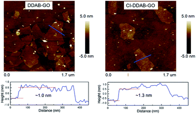
Pristine GO is a hydrophilic material that is unable to be dispersed in organic solvents limiting its application in organic phase conditions. After DDAB functionalization or further CI treatment, DDAB-GO/CI–DDAB-GO can be effectively dispersed in DCB as demonstrated by AFM imaging. The AFM images of DDAB-GO and CI–DDAB-GO deposited from DCB dispersions are shown in Fig. 1. It can be readily inferred that both images are exfoliated single layers as the sheet thickness, given by the height profiles, approximates the reported thickness of pure GO.16 The thickness of CI–DDAB-GO (∼1.3 nm) is larger than that of DDAB-GO (∼1.0 nm), indicating the grafting of chemical groups to the basal plane of DDAB-GO sheets after the CI treatment.The UV-vis absorbance spectrum of DDAB-GO (Fig. 2a) shows a main absorption peak at 227 nm corresponding to the π–π* transition of the graphitic domains in the GO plane.17 This peak is red-shifted to 245 nm and broadened after CI treatment, indicating the enlargement of sp2 conjugation area. In addition, a new absorption peak at 204 nm emerges for CI–DDAB-GO that can be assigned to the characteristic absorption of aromatic rings from CI, implying the attachment of CI to DDAB-GO.
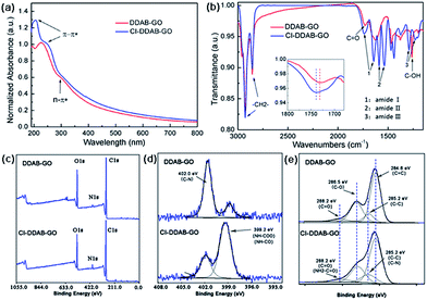 | ||
| Fig. 2 (a) UV-vis spectra of DDAB-GO and CI–DDAB-GO. (b) FTIR spectra of DDAB-GO and CI–DDAB-GO. (c) XPS survey, (d) N 1s, (e) C 1s spectra of DDAB-GO and CI–DDAB-GO. | ||
It has been reported previously that the hydroxyl groups (C–OH) and carboxyl groups (–COOH) in GO can react with isocyanate to form carbamate esters (–NH–COO–) and amide esters (–NH–CO–), respectively.8 The chemical changes of DDAB-GO after CI treatment are also revealed by FTIR and XPS techniques.
The FTIR spectrum of DDAB-GO has characteristic bands at 1732 cm−1, corresponding to the C![[double bond, length as m-dash]](https://www.rsc.org/images/entities/char_e001.gif) O stretching mode from the carboxyl and carbonyl groups of GO, and at 1258 cm−1, corresponding to the C–OH stretching mode from the hydroxyl groups.18 After CI treatment, the C
O stretching mode from the carboxyl and carbonyl groups of GO, and at 1258 cm−1, corresponding to the C–OH stretching mode from the hydroxyl groups.18 After CI treatment, the C![[double bond, length as m-dash]](https://www.rsc.org/images/entities/char_e001.gif) O stretch becomes broadened with its peak shifting to 1739 cm−1 in the FTIR spectrum of CI–DDAB-GO, consistent with the reported absorption band for the C
O stretch becomes broadened with its peak shifting to 1739 cm−1 in the FTIR spectrum of CI–DDAB-GO, consistent with the reported absorption band for the C![[double bond, length as m-dash]](https://www.rsc.org/images/entities/char_e001.gif) O bond from carbamate esters (–NH–COO–).19 This band is also called the amide I mode. A band at 1642 cm−1 can be assigned to the amide I mode of the C
O bond from carbamate esters (–NH–COO–).19 This band is also called the amide I mode. A band at 1642 cm−1 can be assigned to the amide I mode of the C![[double bond, length as m-dash]](https://www.rsc.org/images/entities/char_e001.gif) O stretching from amide esters (–NH–CO–).8 Amide II modes contributed by the N–H in-plane bending, the C–N stretching, and the C–C stretching vibrations are seen at 1590 cm−1 and 1538 cm−1 corresponding to the carbamate and amide esters, respectively. Amide III modes involving the C–N stretching coupled by N–H deformation modes are also observed at 1290 cm−1 and 1228 cm−1. The C–OH stretch disappears in the spectrum of CI–DDAB, indicating the consumption of hydroxyl groups during the CI treatment. The C–H symmetric and asymmetric stretching mode at 2854 cm−1 and 2924 cm−1 corresponding to alkyl chains of DDAB are present in CI–DDAB-GO, suggesting that the ionic bonded DDAB chains at the carboxyl sites of GO are largely preserved after CI treatment.
O stretching from amide esters (–NH–CO–).8 Amide II modes contributed by the N–H in-plane bending, the C–N stretching, and the C–C stretching vibrations are seen at 1590 cm−1 and 1538 cm−1 corresponding to the carbamate and amide esters, respectively. Amide III modes involving the C–N stretching coupled by N–H deformation modes are also observed at 1290 cm−1 and 1228 cm−1. The C–OH stretch disappears in the spectrum of CI–DDAB, indicating the consumption of hydroxyl groups during the CI treatment. The C–H symmetric and asymmetric stretching mode at 2854 cm−1 and 2924 cm−1 corresponding to alkyl chains of DDAB are present in CI–DDAB-GO, suggesting that the ionic bonded DDAB chains at the carboxyl sites of GO are largely preserved after CI treatment.
The XPS survey spectra of DDAB-GO and CI–DDAB-GO (Fig. 2c) show O 1s peak (532 eV), N 1s peak (402 eV), and C 1s peak (285 eV). The N 1s peak is obviously enhanced in CI–DDAB-GO, consistent with the introduction of additional N atoms after CI treatment of DDAB-GO. Two peaks can be fitted at 399.2 eV and 402.0 eV in the high resolution N 1s spectrum (Fig. 2d). For DDAB-GO, the main peak located at 402.0 eV is ascribed to the C–N bonds from the DDAB molecules. The main peak at 399.2 eV for CI–DDAB-GO arises from the carbamate and amide groups.20,21 The C 1s XPS spectra of DDAB-GO and CI–DDAB-GO are shown in Fig. 2e with the peaks fitted by Lorentzian–Gaussian fitting. Four peaks can be fitted for DDAB-GO as follows, C![[double bond, length as m-dash]](https://www.rsc.org/images/entities/char_e001.gif) C–C sp2 bonded carbon atoms from aromatic rings (284.6 eV), C–C bonded carbons from the alkyl chains of DDAB (285.2 eV), C–O bonded carbons from both epoxy and hydroxyl groups (286.5 eV), and C
C–C sp2 bonded carbon atoms from aromatic rings (284.6 eV), C–C bonded carbons from the alkyl chains of DDAB (285.2 eV), C–O bonded carbons from both epoxy and hydroxyl groups (286.5 eV), and C![[double bond, length as m-dash]](https://www.rsc.org/images/entities/char_e001.gif) O bonded carbons from carboxyl groups (288.2 eV). After CI treatment, the peaks at 285.2 eV and 288.2 eV are broadened and enhanced for CI–DDAB-GO. These can be ascribed to the superposition of peaks from C–N bonded carbons (285.2 eV) and the C
O bonded carbons from carboxyl groups (288.2 eV). After CI treatment, the peaks at 285.2 eV and 288.2 eV are broadened and enhanced for CI–DDAB-GO. These can be ascribed to the superposition of peaks from C–N bonded carbons (285.2 eV) and the C![[double bond, length as m-dash]](https://www.rsc.org/images/entities/char_e001.gif) O carbons (288.2 eV) from carbamate/amide groups.22 Therefore, the existence of chemical bonds linking CI and DDAB-GO is clearly confirmed.
O carbons (288.2 eV) from carbamate/amide groups.22 Therefore, the existence of chemical bonds linking CI and DDAB-GO is clearly confirmed.
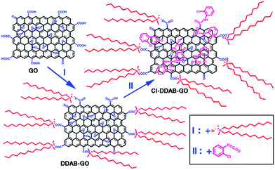
Based on the above analyses, we propose the reaction scheme from GO to DDAB-GO, then to CI–DDAB-GO as depicted in Scheme 1. During the DDAB functionalization, the DDAB cations possessing two long alkyl chains are mainly attached to the ionized carboxylic anions at the edge of GO sheets through ionic bonds as carboxyl groups are more easily ionized than hydroxyl groups. The DDAB-GO dispersed in DCB can covalently react with CI. The aromatic ring of CI can covalently link to the C–OH groups at the basal plane and C–OOH groups at the edge of DDAB-GO sheets by forming carbamate/amide esters. Due to the occupation of carboxylic sites by DDAB, it is believed that the CI groups are mainly bonded to the basal plane of DDAB-GO. Thus, CI treatment of DDAB-GO can provide a complementary route to DDAB functionalization, resulting in CI–DDAB-GO with the edge and basal plane both linked to oleophilic functional groups.
The hydrophilicity of GO is decreased after the DDAB functionalization as revealed by contact angle measurements. The contact angle of deionized water droplets on the surface of a GO deposited film is 30.4°, which increases to 42.3° for DDAB-GO as shown in Fig. 3. A further decrease of hydrophilicity of DDAB-GO results from the CI treatment. The contact angle for CI–DDAB-GO is 65.5°, which is much larger than both GO and DDAB-GO. The decreased hydrophilicity of CI–DDAB-GO compared to DDAB-GO highlights the effectiveness of the CI treatment to impart functionalized GO with improved dispersibility in non-polar solvents and thus may improve the compatibility of CI–DDAB-GO with organic polymers.
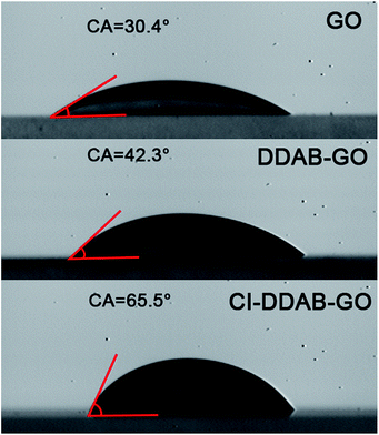 | ||
| Fig. 3 Contact angles of water droplets on the surfaces of GO, DDAB-GO and CI–DDAB-GO deposited films. | ||
Poly(3-hexylthiophene) (P3HT) is a well-known conjugated polymer with good electrical and optical properties that has been widely used in organic electronics. P3HT:GO composites have attracted considerable research attention as they have potential applications as photocatalysts and as photovoltaic materials.23,24 Here, P3HT is chosen to explore the compatibility of the functionalized GO materials with a conjugated polymer.
The optical microscopy images of P3HT, P3HT: 10% DDAB-GO, and P3HT: 10% CI–DDAB-GO are shown in the upper panel of Fig. 4. The surface morphology of P3HT: 10% DDAB-GO is rough compared to that of pure P3HT films. Aggregates with dimensions on the tens of microns scale are induced by DDAB-GO, showing the poor compatibility between P3HT and DDAB-GO. However the morphology of P3HT: 10% CI–DDAB-GO is markedly improved as no aggregation is observed. The AFM images of these film samples are depicted in the bottom panel of Fig. 4. Note that the AFM image of P3HT: 10% DDAB-GO was obtained by scanning the flattest section of the film to avoid the largest aggregated sections. The roughness analysis of the images gives Rq (the root mean square average of the height deviation) of 3.12 nm for P3HT, 13.6 nm for P3HT: 10% DDAB-GO, 7.41 nm for P3HT: 10% CI–DDAB-GO. This provides further confirmation that P3HT: 10% CI–DDAB-GO film possesses a better surface morphology than P3HT: 10% DDAB-GO film.
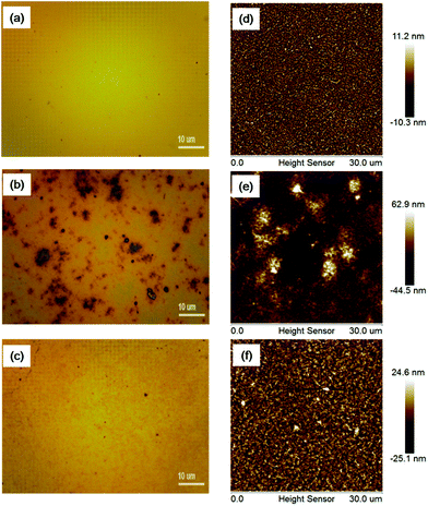 | ||
| Fig. 4 Optical microscopy and AFM images of P3HT (a, d), P3HT: 10% DDAB-GO (b, e), P3HT: 10% CI–DDAB-GO (c, f). | ||
The UV-vis absorption spectra of the three film samples are shown in Fig. 5a. Three peaks corresponding to the 0–0, 0–1, 0–2 absorption transitions in P3HT can be observed in all samples. As reported previously, the 0–0 absorption peak is attributed to transitions associated with intra-chain interactions, while the 0–1 and 0–2 peaks are related to interchain interactions.25 Thus, both I0–1/I0–0 and I0–2/I0–0 can show the magnitude of interchain interactions in P3HT films. The absorption spectra have been normalized at the 0–0 peak to simplify the comparison of peak intensity. The magnitudes of I0–1/I0–0 and I0–2/I0–0 for P3HT: 10% DDAB-GO are lower than those for P3HT. In contrast, P3HT: 10% CI–DDAB-GO shows significantly larger I0–1/I0–0 and I0–2/I0–0. Thus, DDAB-GO decreases interchain interactions of polymer chains when incorporated into P3HT, indicating a higher amorphous content of P3HT induced by DDAB-GO. On the other hand, CI–DDAB-GO can significantly enhance the interchain interactions of P3HT chains. The PL spectra of the three film samples with their intensity normalized at the 0–0 exciton emission peak are shown in Fig. 5b. Similar to the absorption spectra, the 0–1 and 0–2 maxima also represent the intensity of interchain interactions in P3HT.14 From the analysis of the I0–1/I0–0 and I0–2/I0–0 ratio, it is concluded that the interchain interactions of P3HT molecules are effectively weakened after the incorporation of DDAB-GO but enhanced by doping CI–DDAB-GO.
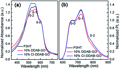 | ||
| Fig. 5 Normalized UV-vis spectra (a) and PL spectra (b) of P3HT, P3HT: 10% DDAB-GO, P3HT: 10% CI–DDAB-GO films. | ||
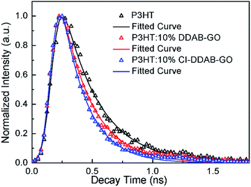
The time resolved photoluminescence decay profiles of P3HT and the composite films recorded at 660 nm (0–0 peak) by the TCSPC technique are shown in Fig. 6. The fitted decay PL lifetimes for P3HT, P3HT: 10% DDAB-GO and P3HT: 10% CI–DDAB-GO are 300 (±2) ps, 249 (±3) ps, and 209 (±5) ps, respectively. Upon the incorporation of 10% DDAB-GO and CI–DDAB-GO, the shortened decay time for excitons of P3HT can be attributed to electron transfer from photo-excited P3HT to DDAB-GO and CI–DDAB-GO.14 The excitons in P3HT: 10% CI–DDAB-GO decay faster than those in P3HT: 10% DDAB-GO even though the GO content is the same. This is likely because the P3HT/GO hetero-interface area in P3HT: 10% CI–DDAB-GO is larger than that in P3HT: 10% DDAB-GO due to the better dispersion of the CI–DDAB-GO sheets in the polymer matrix.
Grazing incidence wide angle X-ray scattering (GIWAXS) was used to investigate the structure of these composite films. The 2-D GIWAXS images of P3HT, P3HT: 10% DDAB-GO, P3HT: 10% CI–DDAB-GO films are shown in Fig. 7a–c respectively. The region selected for intensity projection along qz and qx,y are shown in Fig. 7a as rectangles. A well pronounced (100) peak along with small reflection (200) and (300) peaks observed in all samples can be ascribed to the diffraction of P3HT lamellae.26 P3HT lamellae lie in the (100) plane are formed by π–π stacking of P3HT molecules with their alkyl side chains perpendicular to the plane. Diffraction peaks of P3HT mainly appear at the vertical directions of the 2-D image, indicating that the crystallized domains composed of P3HT lamellae are predominantly oriented parallel to the substrate. When DDAB-GO is doped, (100), (200) and (300) peaks spread out along the rings, implying the random orientation of P3HT crystals. For P3HT: 10% CI–DDAB-GO, these peaks are concentrated to the vertical direction again, implying the recovery of the P3HT crystal order with the comprised lamellae parallel to the substrate. The intensity projection profiles along the qz direction (vertical) presented in Fig. 7d clearly show the (100) peak for P3HT is significantly decreased upon doping with DDAB-GO and CI–DDAB-GO. The (100) peak intensity for P3HT: 10% CI–DDAB-GO is much higher than that for P3HT: 10% DDAB-GO, implying the existence of vertically oriented P3HT lamellae relative to the substrate. An enhancement of in-plane (100) peak for P3HT: 10% CI–DDAB-GO compared to P3HT and P3HT: 10% DDAB-GO is observed from the projection profile along qx,y. The result indicates the existence of vertically oriented P3HT lamellae in P3HT: 10% CI–DDAB-GO film.27
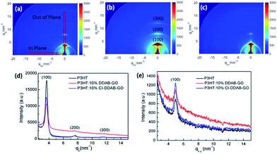 | ||
| Fig. 7 2-D GI-WAXS images of P3HT film (a), P3HT: 10% DDAB-GO film (b), P3HT: 10% CI–DDAB-GO (c); intensity projection along vertical direction (d) and horizontal direction (e). | ||
Thus, structural models can be proposed as follows and depicted in Scheme 2. P3HT films contain crystal domains oriented perpendicular to the substrate in which most P3HT molecules prefer the edge-on configuration. When DDAB-GO sheets are doped, P3HT lamellae become more randomly oriented due to the low compatibility between DDAB-GO and P3HT, effectively reducing the edge-on configuration. CI–DDAB-GO sheets can distribute more uniformly in the P3HT matrix with their sheet orientation parallel to the substrate owing to lateral size restriction,28 thus recovering the ordering of P3HT crystal domains. However, owing to their flexibility, CI–DDAB-GO sheets can be distorted resulting in P3HT crystals being less ordered than in the neat P3HT films.
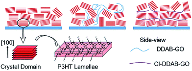 | ||
| Scheme 2 Illustrations of proposed P3HT crystal domain orientation relative to the substrate for neat P3HT film and when doped with DDAB-GO and CI–DDAB-GO. | ||
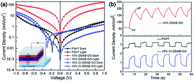
The current density versus voltage curves of three photodiode devices based on P3HT, P3HT: 10% DDAB-GO and P3HT: 10% CI–DDAB-GO in the dark and under illumination are shown in Fig. 8a. All devices have the one direction conducting properties except that based on P3HT: 10% DDAB-GO. Owing to the photoconductivity of P3HT, all devices show enhanced current density under illumination (Jlight) compared to those obtained in the dark (Jdark). The ratio of Jlight to Jdark at +1 V is defined as the on–off ratio in this work which can be regarded as an indicator of the performance of the devices as photodetectors.29 The device based on P3HT film gives an on–off ratio of 1.2. Jlight and Jdark for P3HT: 10% DDAB-GO are both higher compared to the other devices, giving an on–off ratio of 3.4. The dark current of the diode with P3HT: 10% CI–DDAB-GO, however, is much lower than that with pristine P3HT, which offers a relatively high on–off ratio (4.2). Devices based on P3HT and P3HT: 10% CI–DDAB-GO can rapidly respond to the light illumination during light-on/off switching cycles as shown in Fig. 8b, while the device based on P3HT: 10% DDAB-GO needs a much longer time to respond. For the latter device the on–off ratio is reduced to 1.5 after the initial testing cycles (Fig. 8b). Therefore, the incorporation of CI–DDAB-GO can effectively enhance the device performance of P3HT through the reduction of dark current while maintaining the response behavior to light illumination.
As P3HT lamellae are composed of π–π stacked P3HT molecules, P3HT crystal domains have higher charge mobility parallel to the lamellae than in the perpendicular direction. Thus, P3HT film composed of P3HT crystal domains with the lamellae orientation parallel to the substrate possess low charge mobility in the vertical direction, giving low current density for the tested device. In P3HT: 10% DDAB-GO film, the relatively random orientation of P3HT crystal domains gives higher charge mobility in the vertical direction, which is responsible for the large current density both in the dark and under illumination (Jdark, Jlight). Despite possessing less ordering of P3HT crystal domains compared to neat P3HT film, P3HT: 10% CI–DDAB-GO film shows decreased Jdark and Jlight, implying decreased charge mobility in the vertical direction. This can be explained since the horizontally aligned CI–DDAB-GO in the film mostly acts as a charge carrier barrier owing to its insulating nature and effectively blocks the charge transportation pathways in the vertical direction. However, the photo-current (Jlight–Jdark) for P3HT: 10% CI–DDAB-GO is preserved and slightly increased. Therefore, the on–off ratio is enhanced in P3HT: 10% CI–DDAB-GO.
Conclusions
DDAB functionalized GO (DDAB-GO) was treated by 2-chlorophenyl isocyanate (CI) to obtain CI–DDAB-GO with decreased hydrophilicity. It has been demonstrated that CI–DDAB-GO shows improved compatibility with the conjugated polymer, P3HT, compared to DDAB-GO. CI–DDAB-GO sheets can be homogeneously dispersed with P3HT, giving a film morphology much better than P3HT:DDAB-GO composites. The incorporation of CI–DDAB-GO can reduce the dark current of P3HT composite based devices by blocking the vertical charge transport pathways while maintaining the photo-current, showing its potential to enhance the performance of electronic devices based on conjugated polymer composites.Acknowledgements
This work was supported by the National Natural Science Foundation of China (No. 11574181); Research Fund for the Doctoral Program of Higher Education (Grant No. 20130131110004); the Fundamental Research Funds of Shandong University; Open Research Fund of State Key Laboratory Polymer Physics and Chemistry, Changchun Institute of Applied Chemistry, Chinese Academy of Sciences; and the “National Young 1000 Talents” Program of China. Support from the University of Melbourne International Research and Research Training Fund (IRRTF) is acknowledged.References
- K. P. Loh, Q. Bao, G. Eda and M. Chhowalla, Nat. Chem., 2010, 2, 1015–1024 CrossRef CAS PubMed.
- F. Bonaccorso, A. Lombardo, T. Hasan, Z. Sun, L. Colombo and A. C. Ferrari, Mater. Today, 2012, 15, 564–589 CrossRef CAS.
- H. He, J. Klinowski, M. Forster and A. Lerf, Chem. Phys. Lett., 1998, 287, 53–56 CrossRef CAS.
- P. Li, F. Di Stasio, G. Eda, O. Fenwick, S. O. McDonnell, H. L. Anderson, M. Chhowalla and F. Cacialli, ChemPhysChem, 2015, 16, 1258–1262 CrossRef CAS PubMed.
- H. Kim, Y. Miura and C. W. Macosko, Chem. Mater., 2010, 22, 3441–3450 CrossRef CAS.
- S. Hocker, N. Hudson-Smith, H. C. Schniepp and D. E. Kranbuehl, Polymer, 2016, 93, 23–29 CrossRef CAS.
- V. Georgakilas, M. Otyepka, A. B. Bourlinos, V. Chandra, N. Kim, K. C. Kemp, P. Hobza, R. Zboril and K. S. Kim, Chem. Rev., 2012, 112, 6156–6214 CrossRef CAS PubMed.
- S. Stankovich, R. D. Piner, S. T. Nguyen and R. S. Ruoff, Carbon, 2006, 44, 3342–3347 CrossRef CAS.
- D. Chen, H. Feng and J. Li, Chem. Rev., 2012, 112, 6027–6053 CrossRef CAS PubMed.
- F. Zheng, W. L. Xu, H. D. Jin, M. Q. Zhu, W. H. Yuan, X. T. Hao and K. P. Ghiggino, Chem. Commun., 2015, 51, 3824–3827 RSC.
- T. Sainsbury, S. Gnaniah, S. J. Spencer, S. Mignuzzi, N. A. Belsey, K. R. Paton and A. Satti, Carbon, 2017, 114, 367–376 CrossRef CAS.
- Y. Wang, J. W. Shan and G. J. Weng, J. Appl. Phys., 2015, 118, 065101 CrossRef.
- Z. Liu, D. Shen, J. Yu, W. Dai, C. Li, S. Du, N. Jiang, H. Li and C.-T. Lin, RSC Adv., 2016, 6, 22364–22369 RSC.
- F. Zheng, W.-L. Xu, H.-D. Jin, X.-T. Hao and K. P. Ghiggino, RSC Adv., 2015, 5, 89515–89520 RSC.
- Y. Sun, J. H. Seo, C. J. Takacs, J. Seifter and A. J. Heeger, Adv. Mater., 2011, 23, 1679–1683 CrossRef CAS PubMed.
- D. C. Marcano, D. V. Kosynkin, A. S. J. M. Berlin, Z. Z. Sun, L. B. A. A. Slesarev, W. Lu and J. M. Tour, ACS Nano, 2010, 4, 4806–4814 CrossRef CAS PubMed.
- G. Eda, Y. Y. Lin, C. Mattevi, H. Yamaguchi, H. A. Chen, I. S. Chen, C. W. Chen and M. Chhowalla, Adv. Mater., 2010, 22, 505–509 CrossRef CAS PubMed.
- T. Jiang, T. Kuila, N. H. Kim and J. H. Lee, J. Mater. Chem. A, 2014, 2, 10557 CAS.
- A. K. Mishra, D. K. Chattopadhyay, B. Sreedhar and K. V. S. N. Raju, Prog. Org. Coat., 2006, 55, 231–243 CrossRef CAS.
- M. C. Lopes, H. Ribeiro, M. C. Gonçalves Santos, L. M. Seara, F. L. Queiroz Ferreira, R. L. Lavall and G. G. Silva, J. Appl. Polym. Sci., 2017, 134, 44394 CrossRef.
- X. D. Zhuang, Y. Chen, G. Liu, P. P. Li, C. X. Zhu, E. T. Kang, K. G. Noeh, B. Zhang, J. H. Zhu and Y. X. Li, Adv. Mater., 2010, 22, 1731–1735 CrossRef CAS PubMed.
- E. Uchida, Y. Uyama, H. Iwata and Y. Ikada, J. Polym. Sci., Part A: Polym. Chem., 1990, 28, 2837–2844 CrossRef CAS.
- S. Wang, C. T. Nai, X. F. Jiang, Y. Pan, C. H. Tan, M. Nesladek, Q. H. Xu and K. P. Loh, J. Phys. Chem. Lett., 2012, 3, 2332–2336 CrossRef CAS PubMed.
- G. Li, R. Zhu and Y. Yang, Nat. Photonics, 2012, 6, 153–161 CrossRef CAS.
- P. J. Brown, D. S. Thomas, A. Köhler, J. S. Wilson, J.-S. Kim, C. M. Ramsdale, H. Sirringhaus and R. H. Friend, Phys. Rev. B: Condens. Matter Mater. Phys., 2003, 67, 064203 CrossRef.
- E. Verploegen, R. Mondal, C. J. Bettinger, S. Sok, M. F. Toney and Z. Bao, Adv. Funct. Mater., 2010, 20, 3519–3529 CrossRef CAS.
- P. Müller-Buschbaum, Adv. Mater., 2014, 26, 7692–7709 CrossRef PubMed.
- Y. Wang, D. Kurunthu, G. W. Scott and C. J. Bardeen, J. Phys. Chem. C, 2010, 114, 4153–4159 CAS.
- W.-L. Xu, B. Wu, F. Zheng, X.-Y. Yang, H.-D. Jin, F. Zhu and X.-T. Hao, J. Phys. Chem. C, 2015, 119, 21913–21920 CAS.
| This journal is © The Royal Society of Chemistry 2017 |

