
 Open Access Article
 This Open Access Article is licensed under a Creative Commons Attribution-Non Commercial 3.0 Unported Licence
Integration of nanosized ZIF-8 particles onto mesoporous TiO2 nanobeads for enhanced photocatalytic activity†
Qi Liu *,
Beibei Zhou,
Miao Xu and
Guobing Mao*
*,
Beibei Zhou,
Miao Xu and
Guobing Mao*
Department of Materials Science and Engineering, Anhui Polytechnic University, Wuhu, Anhui 241000, P. R. China. E-mail: modieer_67@ahpu.edu.cn; maoguobing@ahpu.edu.cn; Fax: +86 553 2871 252; Tel: +86 553 2871 252
First published on 25th January 2017
Abstract
Hexavalent chromium, or Cr(VI), is a highly toxic contaminant in industrial wastewater that needs to be treated before being released. A Zeolitic Imidazolate Framework ZIF-8 was assembled on the surface of mesoporous TiO2 beads to achieve a TiO2/ZIF-8 heterostructure for photocatalytic reduction of Cr(VI). The TiO2/ZIF-8 nanobeads exhibited remarkable photocatalytic activity of Cr(VI) reduction relative to that of pristine TiO2 nanobeads attributed to the strong Cr(VI) adsorbing properties of ZIF-8 and improved charge transfer efficiency of TiO2/ZIF-8. This work illustrates a strategy for enhanced photocatalysis by modifying the metal oxide catalyst with high surface area Zeolitic Imidazolate Framework to improve adsorption and charge transfer efficiency.
Introduction
Hexavalent chromium, or Cr(VI), is one of the most toxic and dangerous contaminants in industrial wastewater due to its high toxicity and extreme solubility.1–3 Compared to Cr(VI), Cr(III) is less toxic and can be readily precipitated in neutral or alkaline solution. The preferred treatment of Cr(VI) in wastewater is simultaneous detoxification of Cr(VI) to Cr(III) and adsorption of the latter from water.4 Among different detoxifying treatments (such as chemical precipitation, ion exchange, membrane separation, adsorption and photocatalysis), photocatalysis has been proven to be a useful approach in reducing Cr(VI) to Cr(III).5–7 So far, most reported photocatalysts have been based on semiconductors such as TiO2,5–7 CdS,8 SnS2,9 and Ag2S.10 It is known that reactant adsorption or permeation plays an important role in quantum efficiency of the photocatalysis process.11–13 Increasing the surface area of photocatalysts has been proven to be an effective way to provide more reactive sites and better adsorption properties and thus improve the photocatalytic activity.11 However, the limited surface area of traditional semiconductor photocatalysts restricts their photocatalytic activity.Metal–organic frameworks (MOFs) have demonstrated wide applications in molecular recognition, gas separation, catalysis, and drug delivery due to their high surface area, large pore size, tunability and well-defined nanometer-scale cavity, and chemical tailor-ability.14 More specifically, MOFs have been considered as promising candidate materials for photocatalytic reaction, such as water splitting,15,16 CO2 reduction,17–19 photodegradation of organic pollutants,20–22 photocatalytic oxidation of alcohol23 and photocatalytic reduction of Cr(VI).24–26 For instance, Li and his coworkers synthesized an amine-functionalized titanium MOFs (NH2-MIL-125(Ti)) photocatalyst for CO2 photoreduction in acetonitrile with triethanolamine as sacrificial agent under visible light.17 Mahata et al. used different MOFs based on Ni, Co, and Zn as photocatalysts to degrade organic dyes.27 Furthermore, Fe(III)-based MOFs exhibited good photocatalytic activity for Cr(VI) reduction under visible-light.24,26 Although many kinds of MOFs have been proven to be novel photocatalysts, to date, compared with the traditional semiconductor photocatalysts, the photocatalytic efficiency of MOFs photocatalyst is still low due to the low efficiency in exciton generation and charge separation, which limit its practical application. On the other hand, the stability of MOFs during the photocatalytic reaction is an important issue that needed to be further consideration.
Incorporation the high surface area of MOFs and the superiority of MOFs in adsorption together with the high activity of semiconductor photocatalysts provide a promising strategy in photocatalytic application. Recently, semiconductor nano-structures/MOF composites have been intensively studied as photocatalysts (e.g. C3N4/Co-ZIF-9,28 Cd0.2Zn0.8S@UiO-66-NH2,29 TiO2@MIL-53,30 TiO2/ZIF-8,31 Cu3(BTC)2@TiO2,32 ZnO@ZIF-8,33,34 Fe3O4@MIL-101,35 UiO-66/-C3N4,36 ZIF-8/Zn2GeO4,37 CPO-27-Mg/TiO2 38). It has been demonstrated that the combination of semiconductor and MOF showed performance exceed that of the individual component due to their synergistic effect. Besides increasing the surface area of the composites, charge transfer can occur between photoexcited inorganic semiconductors and MOFs, which substantially suppresses electron–hole recombination in the semiconductor and supplies long-life time electrons for photocatalytic reaction.21,32 Despite the rapidly growing interest in semiconductor nanostructures/MOF composites, the studies on these MOF-based hybrid photocatalysts are still scarce and in the infancy.
In this paper, we report the design and fabrication of TiO2/ZIF-8 hybrid photocatalyst. ZIF-8 was chosen as metal–organic framework material owing to its large surface area, excellent thermal and chemical stability.39 The new hybrid TiO2/ZIF-8 nanobeads are produced by decorating the surface of as-synthesized mesoporous TiO2 spheres with ZIF-8 nanoparticles. The hybrid TiO2/ZIF-8 nanobeads were characterized by their morphology, absorption capacity, surface area and photocatalytic reduction of Cr(IV). Compared to TiO2 beads with similar sizes, the catalytic activity of TiO2/ZIF-8 in reducing Cr(VI) to Cr(III) under 300 mW cm−2 full-spectrum light irradiation at room temperature is significantly enhanced. It was found that the enhanced photocatalytic properties of TiO2/ZIF-8 spheres were based on strong Cr(VI) adsorbing properties of ZIF-8 as well as more efficient charge transfer. The stability and long term performance of the new catalyst was investigated by means of its transient photocurrent response to periodic irradiation and repeated photocatalytic reduction experiment of synthetic Cr(IV) waste solution using the recovered photocatalyst. To the best of our knowledge, this work represents the design of hybrid TiO2/ZIF-8 nanosphere and its use for Cr(IV) photoreduction. We hope that the current work could inspire growing interest on the fabrication of other high-performance semiconductor/MOFs composite by taking the advantage of MOFs.
Experimental
Preparation of the mesoporous TiO2 beads
TiO2 colloids were prepared with a modified strategy as previously reported.40 Typically, 0.2 mL of tetrabutyl titanate (TBT) was added to 10 mL of ethylene glycol under stirring. After magnetically stirred for 24 h at room temperature, the solution then poured into 100 mL acetone (containing 0.3% water) under vigorous stirring for about 10 min and then kept at rest for 1 h. The white precipitate was separated by centrifugation and washed several times with ethanol and deionized water to remove excess ethylene glycol from the surfaces of the particles. The obtained powder mixed with 10 mL deionized water and then transferred to a stainless Teflon-lined autoclave of 25 mL inner volume. The hydrothermal synthesis was performed under an auto-generated pressure at 180 °C for 24 h in an electric oven, followed by cooling naturally to room temperature. The white powder was collected by centrifugation and washed thoroughly with alcohol for several times, then dried at 60 °C for 12 h.Synthesis of ZIF-8 nanocrystals
ZIF-8 nanocrystals were prepared according to our previously reported work.37 Typically, 0.587 g of Zn(NO3)2·6H2O and 1.298 g of 2-methylimidazole (Hmim) were dissolved in 40 mL of methanol (MeOH) separately. The Zn2+ solution was added to the Hmim solution under stirring. The mixture was stirred at room temperature for 2 h. The ZIF-8 nanocrystals were separated from the milky colloidal dispersion by centrifugation and washed with anhydrous ethanol for three times, and dried at 60 °C.Preparation of TiO2/ZIF-8 heterostructure
Typically, 0.4 g as-synthesized mesoporous TiO2 beads and 0.587 g Zn(NO3)2·6H2O were added to 40 mL of MeOH and stirred for 1 h. 1.298 g Hmim was dissolved in 40 mL of MeOH to get clear solution, then poured into the former solution under stirring and further stirred for another 1 h at room temperature (theoretical mass ratio 1![[thin space (1/6-em)]](https://www.rsc.org/images/entities/char_2009.gif) :2 of ZIF-8 to TiO2). The obtained precipitate was collected by repeated centrifugation and washing with water and alcohol for several times before drying at 60 °C for 12 h.
:2 of ZIF-8 to TiO2). The obtained precipitate was collected by repeated centrifugation and washing with water and alcohol for several times before drying at 60 °C for 12 h.
Characterization
X-ray diffraction (XRD) measurements were performed on a Philips PW1140/90 diffractometer with CuKa radiation (25 mA and 40 kV) at a scan rate of 2° per min with a step size of 0.02°. The morphology of the samples was observed by scanning electron microscopy (FEI Nova NanoSEM 450) and transmission electron microscopy (JEOL 3010, Japan). The specific surface area of the samples and nitrogen adsorption–desorption isotherms were measured by nitrogen sorption at 77 K on surface area and porosity analyzer (Micromertics ASAP 2020) and calculated by the BET method. Prior to BET surface area measurement, all the samples were degased at 300 °C for 4 h. Thermal gravimetric (TG) measurement was taken on a thermal instrument (Shimadzu Corp. Japan) with a heating rate of 10 °C min−1. 6 mg samples were filled into alumina crucibles and heated in a flow of air with a ramp rate of 5 °C min−1 from room temperature up to 700 °C. UV visible light adsorption spectra was obtained using a UV-Vis spectrophotometer (UV-2600 Shimadzu, Japan).Photoelectrochemical measurement
To prepare the photoelectrodes, 10 mg TiO2 or TiO2/ZIF-8 was added into 1 mL of ethanol. The mixture was stirred for 1 h to ensure that the particles were uniformly dispersed in the solution. 10 μL of this prepared solution was dropped onto the FTO glass substrate (exposed area of 1.0 × 1.0 cm2), and then dried under vacuum condition for 1 h at 60 °C. This step was repeated five times to ensure a uniform coverage of photocatalysts on ITO. Photocurrent measurements were performed in a three-electrode cell using an electrochemical analyzer (CHI-630D, Shanghai Chenhua). The electrolyte was 0.1 M Na2SO4 aqueous solution (pH = 7.0). The TiO2 or TiO2/ZIF-8 photoanodes were used as working electrodes; a Pt wire served as a counter electrode, a Ag/AgCl electrode was used as the reference electrodes. The electrodes were irradiated through the conducting glass by a 300 W Xe lamp. Cyclic voltammetry was performed with a scan rate of 30 mV s−1.Photocatalytic measurement
All the photocatalysts were activated in 200 °C for 4 h before use. The photocatalytic activities of photocatalysts were evaluated by photocatalytic reduction of Cr(VI) under full-light irradiation of a 300 W Xe arc lamp with a cooling water filter. Potassium dichromate (K2Cr2O7) was selected as the Cr(VI) compound. The photocatalytic reduction of Cr(VI) was performed at room temperature in a quartz reactor containing 20 mg photocatalyst and 40 mL of Cr(VI) solution (20 mg L−1 based on Cr in a dilute K2Cr2O7 solution, pH = 7). Nitrogen was then purged through the system, followed by the introduction of 5 mg hole scavenger (ammonium oxalate). As we known, Cr(VI) is often discharged together with hazardous organics from industrial wastewater, these hazardous organics can be used as hole scavenger.Prior to irradiation, the suspension was stirred for 40 min in dark to reach adsorption equilibrium and then was exposed to light irradiation. The concentrations of Cr(VI) was measured by UV-Vis maximum absorbance at 365 nm. The photocatalytic efficiency was determined by the following equation, photocatalytic efficiency = C/C0, where C is the Cr(VI) concentration at time of measurement and C0 is the initial Cr(VI) concentration.
Results and discussion
The XRD patterns of the as-synthesized samples are shown in Fig. 1. The as-synthesized TiO2 precursor was amorphous in structure with essentially no diffraction peaks. After hydrothermal synthesis, all the diffraction peaks of the sample can be assigned to the anatase phase of TiO2 (JCPDS no. 21-1272) with lattice constants of a = b = 3.785 Å and c = 9.514 Å, alpha = beta = gamma = 90°. The broadening of the diffraction peaks indicates the crystallite size of this TiO2 sample is small. The crystallize size D was calculated using the Scherrer equation:| D = 0.9λ/βcosθ |
![[4 with combining macron]](https://www.rsc.org/images/entities/char_0034_0304.gif) 3m)41 by comparing with the simulated ZIF-8 and published pattern,14 which indicates that the product is pure-phase ZIF-8. After growing of ZIF-8 particles on the TiO2 beads, characteristic diffraction peaks of ZIF-8 was observed (2θ = 7.4° and 16.6°). Both distinct characteristic peaks of ZIF-8 and anatase TiO2 were observed, confirming the purity of the product.
3m)41 by comparing with the simulated ZIF-8 and published pattern,14 which indicates that the product is pure-phase ZIF-8. After growing of ZIF-8 particles on the TiO2 beads, characteristic diffraction peaks of ZIF-8 was observed (2θ = 7.4° and 16.6°). Both distinct characteristic peaks of ZIF-8 and anatase TiO2 were observed, confirming the purity of the product.
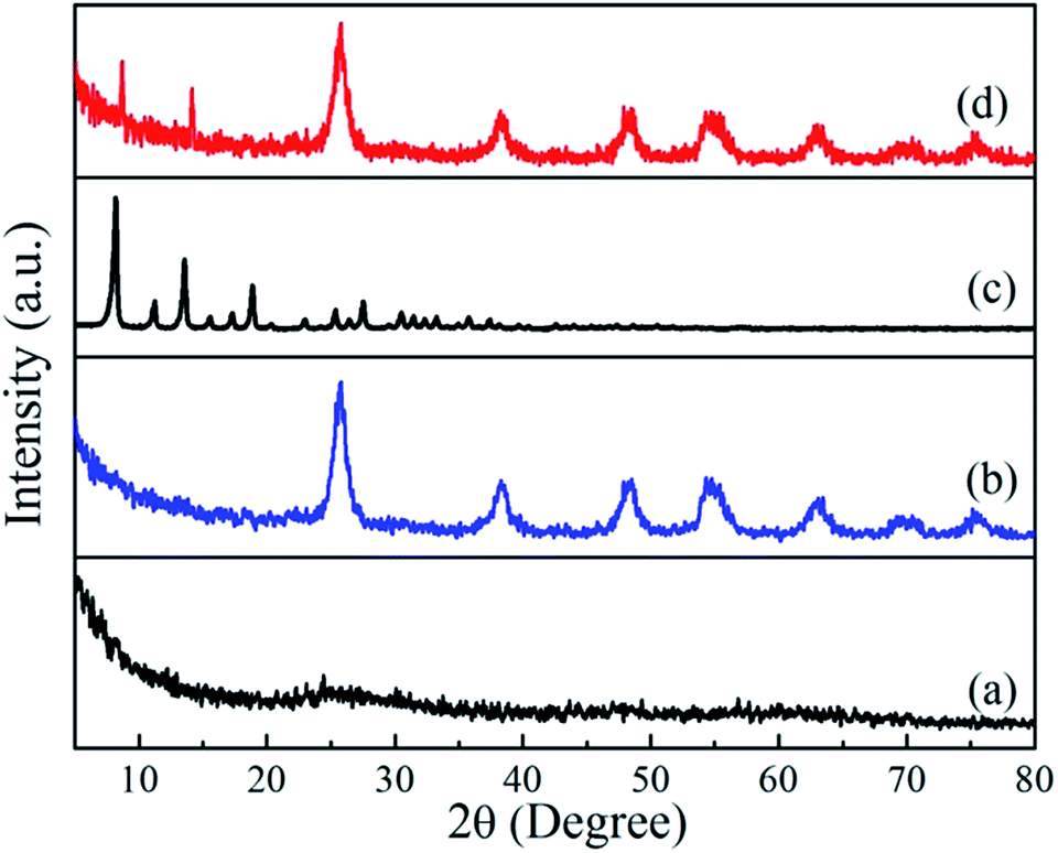 | ||
| Fig. 1 Powder X-ray diffraction patterns of (a) TiO2 colloids, (b) TiO2 beads, (c) pure ZIF-8, and (d) TiO2/ZIF-8 spheres. | ||
The FE-SEM images taken at different magnification show that the prepared TiO2 colloids precursor is entirely composed of uniform, spherical crystallites with a diameter of 300 ± 50 nm. The surfaces of these beads are very smooth without obvious granular features. After hydrothermal treatment, the surface of TiO2 colloids particles were roughened as a result of crystallization. The TiO2 beads are monodisperse beads with a diameter of 250 ± 50 nm. The high magnification SEM image (Fig. 2d) demonstrates that these TiO2 beads are composed of uniform nanocrystals with a size of about 20 ± 5 nm, consistent with the XRD result.
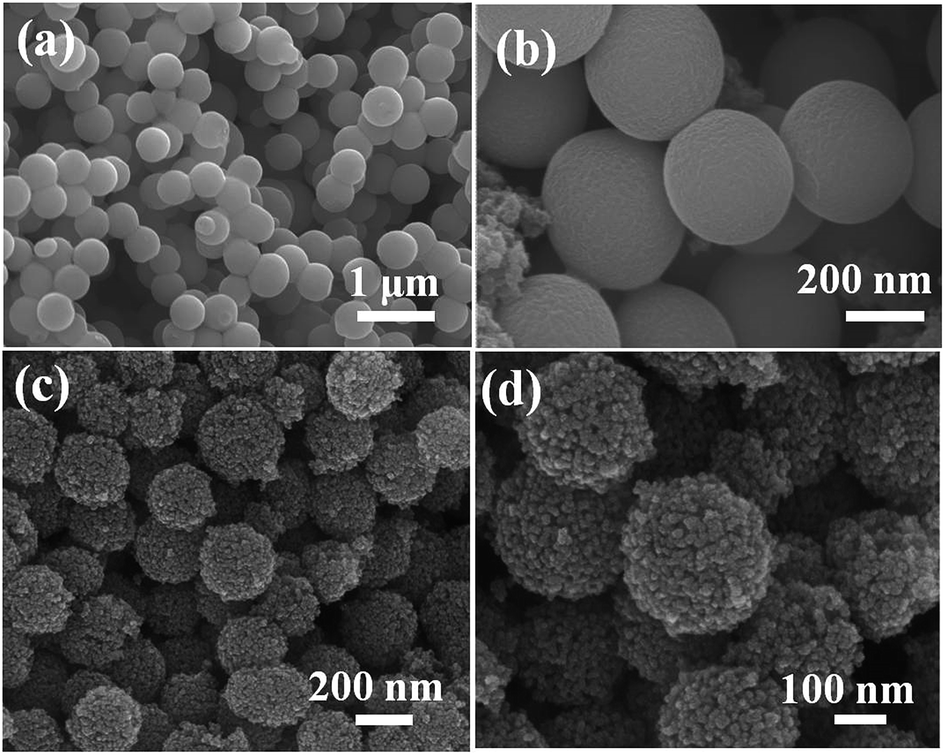 | ||
| Fig. 2 FE-SEM images of TiO2 colloids (a), (b), and TiO2 beads (c), (d). | ||
After in situ growth of ZIF-8 on TiO2 beads, a layer of ZIF-8 polyhedrons were grown on the surface of the TiO2 beads (Fig. 3a). The EDS results also confirm the presence of C, N, O, Ti and Zn in the TiO2/ZIF-8 hybrid spheres (Fig. S1†). A high magnification FE-SEM image of the sample reveals that there are many polyhedrons on the surface of TiO2 beads, which indicates that the ZIF-8 particles were successfully decorated onto the beads to form TiO2/ZIF-8 hybrid nanospheres (Fig. 3b). The ZIF-8 polyhedrons on the TiO2 beads are 40–70 nm in size, which are similar with those ZIF-8 crystals synthesized in the absence of TiO2 beads (Fig. S2†). Discrete ZIF-8 polyhedrons of approximately 50 nm were decorated on the surface of TiO2 beads, as shown in the TEM images of TiO2@ZIF-8 nanobeads (Fig. 3c and d). By means of UV-vis spectroscopy (Fig. S3†), it was observed that the spectrum absorption edge of TiO2/ZIF-8 was slightly blue-shifted compared to the TiO2.
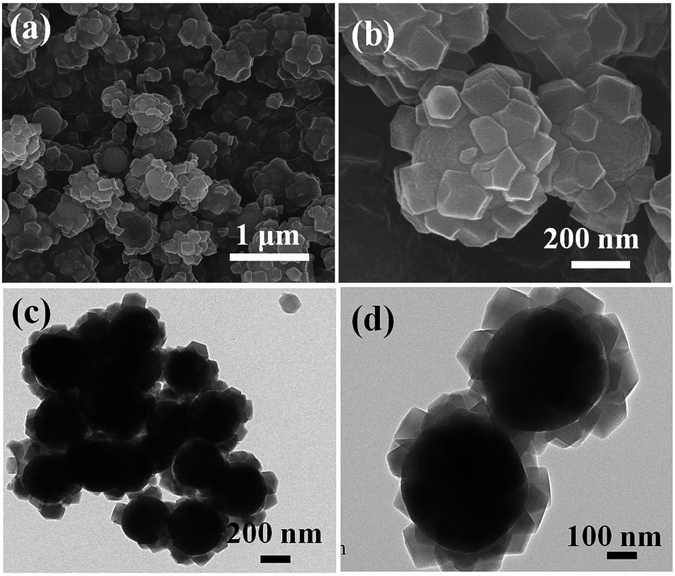 | ||
| Fig. 3 (a) and (b) FE-SEM images, and (c) and (d) TEM images of the TiO2/ZIF-8 hybrid beads. | ||
Fig. 4 shows the nitrogen adsorption–desorption isotherms of TiO2 beads, ZIF-8 and TiO2/ZIF-8 hybrid nanospheres. The TiO2 beads with surface decorated with ZIF-8 nanoparticles exhibit higher BET area due to the high surface area of ZIF-8 as compared to TiO2 beads. The specific BET surface area of TiO2 beads, ZIF-8 and TiO2/ZIF-8 are about 250 m2 g−1, 1058 m2 g−1 and 397 m2 g−1, respectively. ZIF-8 (Fig. 4a) shows a typical type I nitrogen adsorption–desorption isotherm,42 which fit well with the microporous frameworks of ZIF-8.37 The obvious hysteresis loop at high relative pressure (0.8–0.9) indicates the existence of textural macroporosity formed by packing of ZIF-8 crystals, consistent with some previous literature.34,37,43 On the other hand, TiO2 beads exhibits a type IV isotherm with an H3 hysteresis loop according to the Brunauer–Deming–Deming–Teller (BDDT) classification, indicating a mesoporous characteristic.44,45 The initial adsorption of TiO2/ZIF-8 is higher than that of TiO2 (Fig. 4b and c), indicating that micropores exist in TiO2/ZIF-8 hybrid nanospheres,42 which can be attributed to the frameworks of ZIF-8 particles. The adsorption of TiO2/ZIF-8 at high pressure corresponds to composite spherical morphology of the sample, resulting from mesoporous TiO2 beads and microporous ZIF-8 particles.
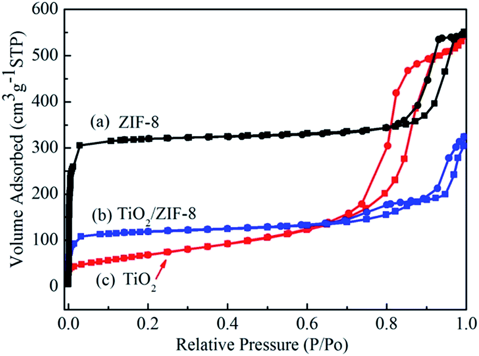 | ||
| Fig. 4 N2 adsorption–desorption isotherms of (a) ZIF-8, (b) TiO2/ZIF-8, (c) TiO2 beads. | ||
To determine the content of ZIF-8 in TiO2/ZIF-8 composites, TG-DTA analysis of these three samples was carried out in air atmosphere, as shown in Fig. 5. The TG of ZIF-8 exhibits a 75% total mass loss up to ca. 700 °C in two steps. For the bare TiO2 beads, TG analysis shows only 1.7% mass loss is observed up to 700 °C, which can be attributed to the desorption of H2O adsorbed on the surfaces of the beads. The weight loss of TiO2/ZIF-8 at the beginning stage (∼1.5%) is the vaporization of adsorbed water or methanol in the sample. The obvious weight loss occurred in the range of 250–580 °C owing to rapid decomposition of ZIF-8 molecules. When the temperature reaches 600 °C, ZIF-8 molecules are transformed to ZnO completely. A total mass loss of ∼14.18% in the measured temperature range means that the prepared sample contains around 20 wt% ZIF-8 and 80 wt% TiO2 on the basis of the weight loss of pure ZIF-8 in air (∼75%). The actual amount of ZIF-8 grown on TiO2 is smaller than the theoretical value (theoretical ZIF-8/TiO2 mass ratio of 1:2). This can be explained by the fact that apart from ZIF-8 growth on TiO2, ZIF-8 also crystallizes in the solution, consuming some of its precursors.
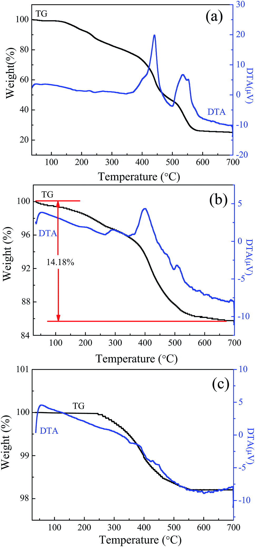 | ||
| Fig. 5 TG (black curve) and DTA (blue curve) analysis of (a) ZIF-8, (b) TiO2/ZIF-8, (c) TiO2 beads. | ||
The photocatalysis performance of TiO2/ZIF-8 in Cr(VI) aqueous solutions is shown in Fig. 6a, as compared with that of TiO2 and ZIF-8 nanoparticles. Under light irradiation, TiO2 in the TiO2/ZIF-8 hybrid nanospheres was excited. The electrons from the excited TiO2 can transfer to the ZIF-8, and reduce the Cr(VI) to Cr(III). The control Cr(VI) reduction experiment performed in the absence of the photocatalyst showed no obvious decrease of Cr(VI) concentration, proving that the Cr(VI) reduction reaction is driven by light with the photocatalyst. Although several MOFs have recently been shown to have good photocatalytic activity under light illumination,17,46 there was no remarkably change of Cr(VI) concentration detected for 60 min irradiation using pure ZIF-8 as photocatalyst. Only ∼10% of Cr(VI) is removed after 60 min irradiation, which is due to the cooperation of weak photocatalytic activity and adsorption of ZIF-8. The pure TiO2 beads showed photocatalytic reduction of Cr(VI) of ∼80% after 60 min irradiation. After incorporation of ZIF-8 nanoparticles, the photocatalytic activity of TiO2/ZIF-8 hybrid spheres towards Cr(VI) is remarkably enhanced. For the photocatalytic reduction of Cr(VI), around 99% of Cr(VI) was removed after 60 min irradiation. The removal efficiency is better than that of TiO2 and ZIF-8, exhibiting enhanced photocatalysis properties. First, the high BET surface and the porous structure of ZIF-8 are beneficial to absorption and permeation of Cr(VI) species. Second, in neutral conditions (pH = 7), ZIF-8 particles exhibit positive charge47 and the main species of Cr(VI) in neutral aqueous solution is CrO42− anion.34,48 Therefore, CrO42− could be effectively adsorbed around the TiO2/ZIF-8 photocatalyst by electrostatic interaction, which lead to better photocatalytic activity of Cr(VI) on TiO2/ZIF-8. Time-dependent evolution of the photocatalytic removal of Cr(VI) by TiO2/ZIF-8 is characterized by optical absorption measurements, as shown in Fig. 6b. One can see the absorption peak at 365 nm ascribed to Cr(VI) ion34,49 decreases rapidly and remarkably with the increase of time and almost disappears after 60 min, which demonstrates the photocatalytic reduction of Cr(VI) over TiO2/ZIF-8. The final concentration of the Cr ions remaining in the solution after 60 min of UV light irradiation drops to 0.06 mg L−1 from the initial 20 mg L−1, and the solution becomes colorless, indicating that the TiO2/ZIF-8 can almost thoroughly remove Cr(VI) ions from the wastewater.
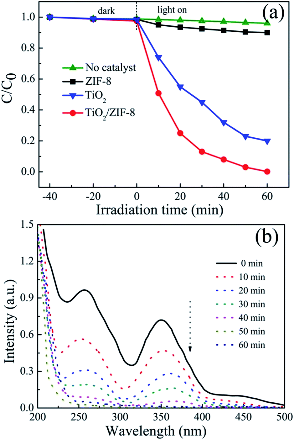 | ||
| Fig. 6 (a) Reduction profiles of photocatalytic reduction of Cr(VI) over various photocatalysts; reaction condition: 20 mg photocatalyst, 40 mL of 20 mg L−1 Cr(VI), pH = 7; (b) absorption spectra of the Cr(VI) solution after photocatalytic reaction for different times over TiO2/ZIF-8. | ||
It is worthy to note that TiO2/ZIF-8 was stable during the whole photocatalytic reduction process. The XRD patterns before and after photocatalysis are almost same, as shown in Fig. S5. † In addition, no obvious morphology change was observed after photocatalysis process (Fig. S6†). The stability and reusability of the photocatalysts are very important for photocatalytic application. To further evaluate the long term performance of the TiO2/ZIF-8 photocatalysts, photocatalytic reduction of Cr(VI) by irradiation using the recycled photocatalysts was conducted. After each reaction, the used photocatalyst was recovered by filtration, washed with water and ethanol, and then dried under vacuum. Fig. 7b shows the transient photocurrent responses of TiO2 beads and TiO2/ZIF-8 under intermittent light illumination. The photocurrent density of TiO2 beads, ZIF-8 and TiO2/ZIF-8 are about 4.3 and 3.4 μA cm−2, respectively. The incorporation of ZIF-8 particles on TiO2 enhance the photocurrent significantly. This indicates that the separation efficiency of photoinduced electron–hole (e−–h+) pairs and the lifetime of the photogenerated charge carriers are improved. For semiconductor/MOF photocatalysts, Jiang proved that the photogenerated electrons can be effectively transferred from the semiconductor to the MOF, which not only facilitates charge separation in the semiconductor but supplies energetic electrons to molecules adsorbed on the MOF.21,32 So, the higher photocatalytic activity of the TiO2/ZIF-8 toward reduction of Cr(VI) relative to that of the TiO2 sample should be attributed to synergistic combination of ZIF-8 and TiO2 nanobeads. Firstly, ZIF-8 can effectively adsorb the dissolved Cr(VI) in the water solution; secondly, the charge transfer of TiO2/ZIF-8 is more efficient than TiO2 alone. Both the improvement lead to higher photocurrent density of TiO2@ZIF-8 nanobeads.
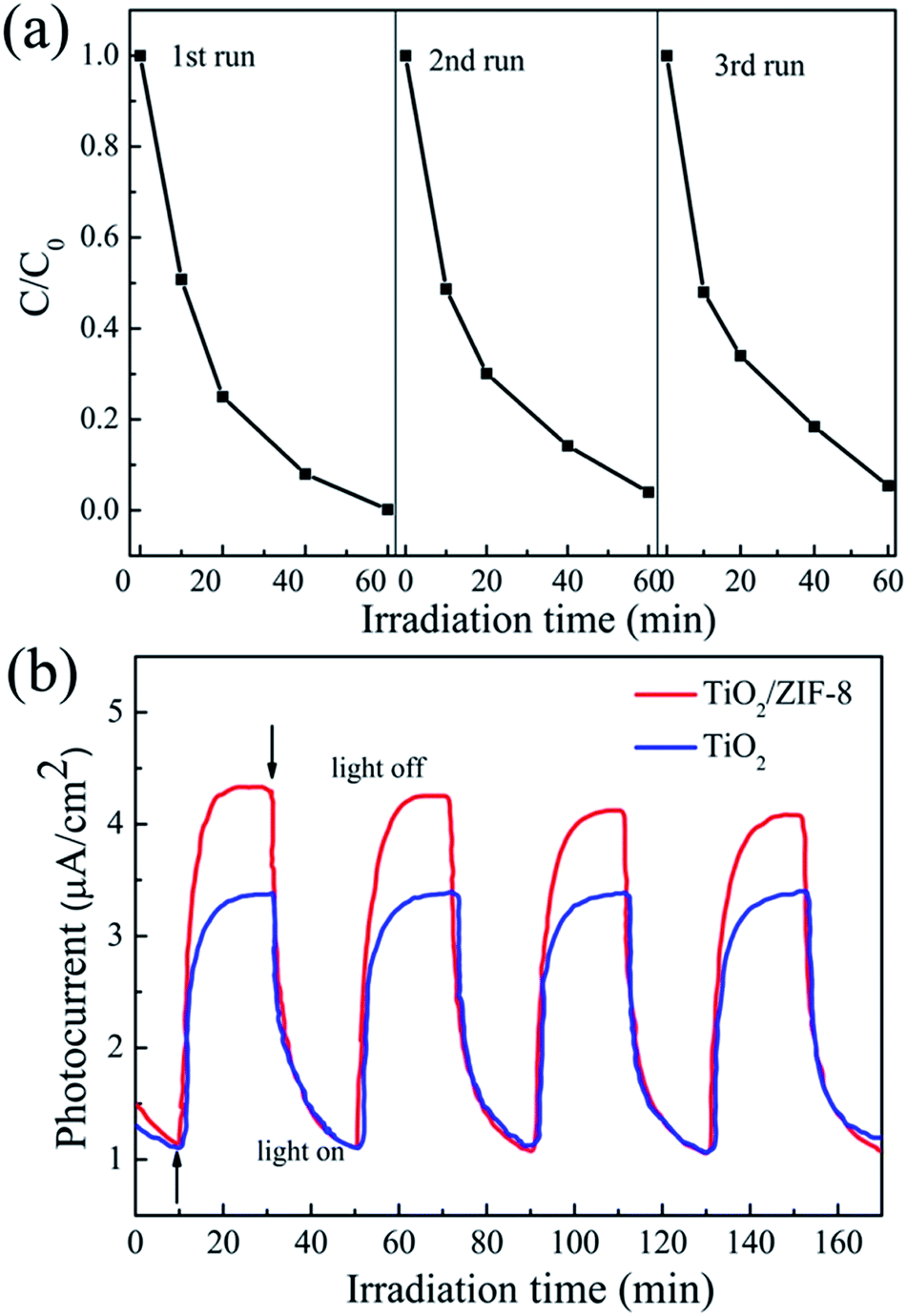 | ||
| Fig. 7 (a) Recycling test on TiO2/ZIF-8 for photocatalytic reduction of Cr(VI). (b) Transient photocurrent response of TiO2/ZIF-8 and TiO2 in 0.1 M Na2SO4 aqueous solution. | ||
Conclusions
In conclusion, TiO2/ZIF-8 hybrid nanospheres have been successfully prepared by depositing nanosized ZIF-8 particles on the surfaces of mesoporous TiO2 nanobeads. As a result, the obtained heterostructures show higher BET area due to the high surface area of ZIF-8 as compared to TiO2 beads. TG-DTA analysis result indicate that the prepared sample contains around 20 wt% ZIF-8 and 80 wt% TiO2. The TiO2/ZIF-8 hybrid nanospheres exhibited enhanced photocatalytic activity of Cr(VI) reduction than pristine TiO2 beads, which can be attributed to the strong Cr(VI) adsorption property of ZIF-8 as well as more efficient charge transfer compared to pristine TiO2 beads. It is anticipated that the strategy for implementing MOF structures in photocatalyst shown here can be applied to other catalytic systems for enhanced photocatalytic conversion efficiency.Acknowledgements
This work was supported by the National Natural Science Foundation of China (No. 51302001 and 21301002), Anhui Province Foundation for Returns (2016) and Funds for Distinguished Young Scientists of Anhui Polytechnic University (No. 2015JQ02).Notes and references
- S. Rengaraj, S. Venkataraj, J.-W. Yeon, Y. Kim, X. Z. Li and G. K. H. Pang, Appl. Catal., B, 2007, 77, 157–165 CrossRef CAS.
- D. Mohan and C. U. Pittman Jr, J. Hazard. Mater., 2006, 137, 762–811 CrossRef CAS PubMed.
- V. K. Gupta, A. Rastogi and A. Nayak, J. Colloid Interface Sci., 2010, 342, 135–141 CrossRef CAS PubMed.
- D. Shao, X. Wang and Q. Fan, Microporous Mesoporous Mater., 2009, 117, 243–248 CrossRef CAS.
- F. D. Kuanping Gong, Z. Xia, M. Durstock and L. Dai, Science, 2009, 323, 760–764 CrossRef PubMed.
- P. Mohapatra, S. K. Samantaray and K. Parida, J. Photochem. Photobiol., A, 2005, 170, 189–194 CrossRef CAS.
- L. Wang, S. Z. Kang, X. Li, L. Qin, H. Yan and J. Mu, Mater. Chem. Phys., 2016, 178, 190–195 CrossRef CAS.
- X. Liu, L. Pan, T. Lv, G. Zhu, Z. Sun and C. Sun, Chem. Commun., 2011, 47, 11984–11986 RSC.
- Y. C. Zhang, J. Li, M. Zhang and D. D. Dionysiou, Environ. Sci. Technol., 2011, 45, 9324–9331 CrossRef CAS PubMed.
- W. Yang, L. Zhang, Y. Hu, Y. Zhong, H. B. Wu and X. W. Lou, Angew. Chem., Int. Ed., 2012, 51, 11501–11504 CrossRef CAS PubMed.
- H. Tong, S. Ouyang, Y. Bi, N. Umezawa, M. Oshikiri and J. Ye, Adv. Mater., 2012, 24, 229–251 CrossRef CAS PubMed.
- X. Chang, T. Wang and J. Gong, Energy Environ. Sci., 2016, 9, 2177–2196 CAS.
- W. Tu, Y. Zhou and Z. Zou, Adv. Mater., 2014, 26, 4607–4626 CrossRef CAS PubMed.
- K. S. Park, Z. Ni, A. P. Cote, J. Y. Choi, R. Huang, F. J. Uribe-Romo, H. K. Chae, M. O'Keeffe and O. M. Yaghi, Proc. Natl. Acad. Sci. U. S. A., 2006, 103, 10186–10191 CrossRef CAS PubMed.
- G. Huang, Y. Chen and H. Jiang, Acta Chim. Sin., 2016, 74, 113–129 CrossRef CAS.
- J. H. Cavka, S. Jakobsen, U. Olsbye, N. Guillou, C. Lamberti, S. Bordiga and K. P. Lillerud, J. Am. Chem. Soc., 2008, 130, 13850–13851 CrossRef PubMed.
- Y. H. Fu, D. R. Sun, Y. J. Chen, R. K. Huang, Z. X. Ding, X. Z. Fu and Z. H. Li, Angew. Chem., Int. Ed., 2012, 51, 3364–3367 CrossRef CAS PubMed.
- H. Q. Xu, J. Hu, D. Wang, Z. Li, Q. Zhang, Y. Luo, S. H. Yu and H. L. Jiang, J. Am. Chem. Soc., 2015, 137, 13440–13443 CrossRef CAS PubMed.
- A. Dhakshinamoorthy, A. M. Asiri and H. Garcia, Angew. Chem., Int. Ed., 2016, 55, 5414–5445 CrossRef CAS PubMed.
- K. G. Laurier, F. Vermoortele, R. Ameloot, D. E. De Vos, J. Hofkens and M. B. Roeffaers, J. Am. Chem. Soc., 2013, 135, 14488–14491 CrossRef CAS PubMed.
- Y. Li, H. Xu, S. Ouyang and J. Ye, Phys. Chem. Chem. Phys., 2016, 18, 7563–7572 RSC.
- D. Wang, M. Wang and Z. Li, ACS Catal., 2015, 5, 6852–6857 CrossRef CAS.
- W. G. Tian, C. Xiao, R. V. Maligal-Ganesh, X. Li and W. Huang, Chem. Eng. Sci., 2015, 124, 45–51 CrossRef.
- L. Shi, T. Wang, H. Zhang, K. Chang, X. Meng, H. Liu and J. Ye, Adv. Sci., 2015, 2, 1500006 CrossRef PubMed.
- R. Liang, L. Shen, F. Jing, W. Wu, Q. Na, L. Rui and W. Ling, Appl. Catal., B, 2015, 162, 245–251 CrossRef CAS.
- R. Liang, F. Jing, L. Shen, N. Qin and L. Wu, J. Hazard. Mater., 2015, 287, 364–372 CrossRef CAS PubMed.
- P. Mahata, G. Madras and S. Natarajan, J. Phys. Chem. B, 2006, 110, 13759–13768 CrossRef CAS PubMed.
- S. Wang, J. Lin and X. Wang, Phys. Chem. Chem. Phys., 2014, 16, 14656–14660 RSC.
- Y. Su, Z. Zhang, H. Liu and Y. Wang, Appl. Catal., B, 2017, 200, 448–457 CrossRef CAS.
- N. Chang, D. Y. He, Y. X. Li, Z. W. Tang and Y. F. Huang, RSC Adv., 2016, 6, 71481–71484 RSC.
- X. Zeng, L. Huang, C. Wang, J. Wang, J. Li and X. Luo, ACS Appl. Mater. Interfaces, 2016, 8, 20274–20282 CAS.
- R. Li, J. Hu, M. Deng, H. Wang, X. Wang, Y. Hu, H. L. Jiang, J. Jiang, Q. Zhang, Y. Xie and Y. Xiong, Adv. Mater., 2014, 26, 4783–4788 CrossRef CAS PubMed.
- W. Zhan, Q. Kuang, J. Zhou, X. Kong, Z. Xie and L. Zheng, J. Am. Chem. Soc., 2013, 135, 1926–1933 CrossRef CAS PubMed.
- X. Wang, J. Liu, S. Leong, X. Lin, J. Wei, B. Kong, Y. Xu, Z. X. Low, J. Yao and H. Wang, ACS Appl. Mater. Interfaces, 2016, 8, 9080–9087 CAS.
- X. Yue, W. Guo, X. Li, H. Zhou and R. Wang, Environ. Sci. Pollut. Res., 2016, 23, 1–9 CrossRef PubMed.
- R. Wang, L. Gu, J. Zhou, X. Liu, F. Teng, C. Li, Y. Shen and Y. Yuan, Adv. Mater. Interfaces, 2015, 2, 1500037 CrossRef.
- Q. Liu, Z. X. Low, L. Li, A. Razmjou, K. Wang, J. Yao and H. Wang, J. Mater. Chem. A, 2013, 1, 11563–11569 CAS.
- M. Wang, D. Wang and Z. Li, Appl. Catal., B, 2016, 183, 47–52 CrossRef CAS.
- X. C. Huang, Y. Y. Lin, J. P. Zhang and X. M. Chen, Angew. Chem., Int. Ed., 2006, 45, 1557–1559 CrossRef CAS PubMed.
- X. Jiang, T. Herricks and Y. Xia, Adv. Mater., 2003, 15, 1205–1209 CrossRef CAS.
- U. P. N. Tran, K. K. A. Le and N. T. S. Phan, ACS Catal., 2011, 1, 120–127 CrossRef CAS.
- M. Kruk and M. Jaroniec, Chem. Mater., 2001, 13, 3169–3183 CrossRef CAS.
- M. He, J. Yao, Q. Liu, K. Wang, F. Chen and H. Wang, Microporous Mesoporous Mater., 2014, 184, 55–60 CrossRef CAS.
- S. C. Yan, S. X. Ouyang, J. Gao, M. Yang, J. Y. Feng, X. X. Fan, L. J. Wan, Z. S. Li, J. H. Ye, Y. Zhou and Z. G. Zou, Angew. Chem., Int. Ed., 2010, 49, 6400–6404 CrossRef CAS PubMed.
- X. W. Lou, D. Deng, J. Y. Lee and L. A. Archer, J. Mater. Chem., 2008, 18, 4397–4401 RSC.
- C. Wang, Z. Xie, K. E. deKrafft and W. Lin, J. Am. Chem. Soc., 2011, 133, 13445–13454 CrossRef CAS PubMed.
- N. A. Khan, B. K. Jung, Z. Hasan and S. H. Jhung, J. Hazard. Mater., 2015, 282, 194–200 CrossRef CAS PubMed.
- X. Wang, J. Mater. Chem., 2010, 20, 8582–8590 RSC.
- J. Yu, S. Zhuang, X. Xu, W. Zhu, B. Feng and J. Hu, J. Mater. Chem. A, 2014, 3, 1199–1207 Search PubMed.
Footnote |
| † Electronic supplementary information (ESI) available: Characterizations and supporting images. See DOI: 10.1039/c6ra28277f |
| This journal is © The Royal Society of Chemistry 2017 |