 Open Access Article
Creative Commons Attribution 3.0 Unported Licence
Laser-induced growth of YVO4:Eu3+ nanoparticles from sequential flowing aqueous suspension†
Haohao Wang *a,
Marcus Lau
 b,
Takumi Sannomiyac,
Bilal Gökce
 b,
Stephan Barcikowski
 b,
Osamu Odawarac and
Hiroyuki Wadac
aInterdisciplinary Graduate School of Science and Engineering, Tokyo Institute of Technology, 4259 Nagatsuta-cho, Midori-ku, Yokohama 226-8502, Japan. E-mail: haohao.w.aa@m.titech.ac.jp; Fax: +81-45-924-5567; Tel: +81-45-924-5567
bInstitute of Technical Chemistry I, Center for Nanointegration Duisburg-Essen (CENIDE), University of Duisburg-Essen, 45141 Essen, Germany
cSchool of Materials and Chemical Technology, Tokyo Institute of Technology, 4259 Nagatsuta-cho, Midori-ku, Yokohama 226-8502, Japan
First published on 30th January 2017
Abstract
Ligand-free lanthanide ion-doped oxide nanoparticles have critical biological applications. An environmentally friendly and chemically green synthesis of YVO4:Eu3+ nanoparticles with high crystallinity is achieved using a physical method, laser irradiation from sequential flowing aqueous suspension in a free liquid reactor. The fabricated nanoparticles have an ovoid or spindle shape depending on the number of laser irradiation cycles. A transmission electron microscopy study showed that spindle-like particles are single-crystalline with high crystallinity, which is beneficial for high luminescence efficiency. Strong light emission even from a single particle was confirmed by cathodoluminescence mapping. A possible mechanism of nanoparticle formation was proposed as follows. Primary nanocrystals were produced from the plasma plume and self-assembled into ovoid-like nanoparticles via oriented attachment. After several cycles of laser irradiation, we observed spindle-like nanoparticles that were much longer than the ovoid-like particles. The spindle-like nanoparticles grew as a result of the diffusion and coalescence of the ovoid-like nanoparticles during repetitive laser irradiation. These findings provide useful information for the formation of ligand-free luminescent nanoparticles with different sizes based on YVO4.
Introduction
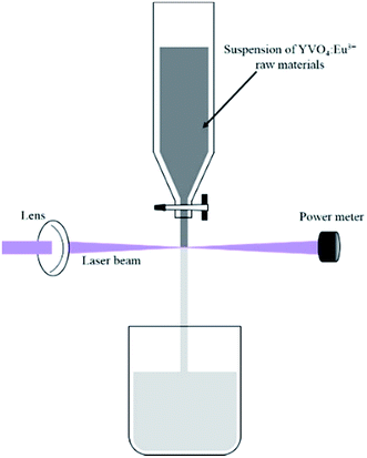
Pulsed laser ablation in liquid (PLAL) has attracted considerable interest as an innovative technique to prepare various colloidal nanoparticles since the pioneering works in the early 1990s by Fojtik and co-workers.1–8 When the surface of the target material is irradiated by a laser beam with high fluence, a plasma plume containing atoms, ions, and clusters will be induced and rapidly quenched by confinement in the liquid phase. Nanoparticles with sizes much smaller than the target materials are collected in the liquid. In general, the experimental process appears to be very simple: a piece of metallic or a moulding pellet of non-metallic material is immersed at the bottom of a container covered with liquid and the laser beam is focused on its surface. With the advancement of PLAL, Koshizaki and co-workers9–12 developed a method to produce the submicron spheres from the nanoparticles via pulsed laser irradiation with low fluence. This process is referred to as pulsed laser melting in liquid (PLML). Unlike in PLAL, during PLML, the laser beam directly passes through the colloid and interacts with nanoparticles in a vessel instead of a piece of bulk material. Thus, in PLML, the raw materials can be rapidly changed to droplets with adequate absorption of laser energy (below the threshold of ablation). The formed droplets can also fuse and merge with neighboring ones during repetitive laser irradiation.In contrast to the abovementioned experimental setup, Wagener et al.13 proposed a novel process in which the suspensions containing the target raw particles flow downstream from a free liquid reactor, and the liquid filament is exposed to a pulsed laser beam. The liquid filament used was quite narrow. PLAL and PLML could be happened depending on the applied laser fluence. During the laser irradiation, the fluence gradients along the laser beam would be effectively decreased compared with in the setup described for PLML. In addition, the efficiency of nanoparticle production is improved compared to PLAL.14 The detailed experiment setup is depicted in Fig. 1. Lau et al.15,16 developed and applied this technique to produce zinc oxide and carbide, they showed that the laser processing decreased the particle size and resulted in an irregular morphology.
Lanthanide ion-doped oxide nanoparticles have aroused great attention because of their interesting electrical, chemical and optical properties.17–23 YVO4 is one of the most classical matrices for lanthanide doping.24 In conjunction with different dopant ions, it is possible to obtain multicolor emission via excitation with ultraviolet (UV) light, and highly efficient up-conversion emission is possible via near-infrared (NIR) excitation.20,25,26 In this study, we focused on Eu3+-doped YVO4 (YVO4:Eu3+), which is known as a useful probe for biological applications. Casanova et al.28 utilized single YVO4:Eu3+ particles to quantitatively measure the generation of reactive oxygen species such as H2O2 in living cells. Alexandrou et al.27,29 used these nanoparticles to label toxins in membranes of Madin–Darby canine kidney (MDCK) cell and image the sodium channel in the live cardiac myocytes of frogs.
We previously reported that YVO4:Eu3+ poly-crystals with ovoid shape were fabricated by PLAL.30 As far as we know, there have been sporadic reports of the polycrystalline nanoparticles with the similar morphology. Lin et al.31 synthesized CuO poly-crystals with spindle shape by PLAL with the assistance of electrical field. Spindle-like GaOOH and ZnO poly-crystals were also synthesized by PLAL in CTAB solution.32,33
In this study, a free liquid reactor was utilized to synthesize ligand-free YVO4:Eu3+ nanoparticles. Interestingly, the fabricated nanoparticles had ovoid or spindle shape depending on the number of laser irradiation cycles. In contrast to abovementioned reports, we fabricated well-defined, YVO4:Eu3+ single-crystalline by this technique without any surfactants. Moreover, a possible mechanism of particle formation was discussed.
Methods
Commercial Y0.95VO4:0.05Eu3+ powder containing micron-sized particles was dispersed in 50 ml deionized water at a concentration of 0.1 wt%. Subsequently, the suspension was transferred into a free liquid reactor with a 1.3 mm capillary at the bottom of the reservoir, forming a liquid filament. The suspension flowed downstream into the container from the reactor after pulsed laser irradiation. The same process was recirculated for 12 times, and the suspension was collected after one, three, five, eight, and 12 irradiation cycles, which were named L1, L3, L5, L8 and L12, respectively. A power meter was set at the same horizontal level with the laser beam behind the liquid filament to determine the laser power. The main experimental setup is illustrated in Fig. 1. Irradiation was carried out using a Nd:YAG pulsed laser, which provided 40 ns pulse at a wavelength of 355 nm and a repetition rate of 85 kHz. The laser fluence was altered by changing the distance between the liquid filament and the lens, and the input laser fluence of 60 mJ cm−2 pulse was set after experimental optimization. The samples obtained at this laser fluence for different numbers of laser irradiation cycles were collected and discussed throughout the paper. In this study, the effect of the laser fluence is not emphasized because particle morphology and sizes are quite similar when the laser fluence increased to 140 mJ cm−2. However, similar nanoparticles were not observed when the laser fluence was lower than 30 mJ cm−2 pulse, which might be lower than the threshold for producing YVO4:Eu3+ nanoparticles.The phases of the samples were determined by X-ray diffraction (XRD, MiniFlex 600, Rigaku) with a Cu-kα1/kα2 radiation (ratio = 0.514) at 40 kV and 15 mA. All patterns were recorded with a step width of 2θ = 0.02 deg. The particle sizes and morphologies were observed using scanning electron microscopy (SEM, Hitachi High-technologies, S-4800). Transmission electron microscopy (TEM, JEOL, R005) was used to characterize the lattice fringes at high resolution with an acceleration voltage of 300 kV. The optical properties of the samples were analyzed by photoluminescence spectrophotometry (PL, Hitachi High-technologies, F-7000) with a 150 V Xe lamp at room temperature. The cathodoluminescence (CL) curves were collected using the system combined with TEM (JEM-2100F). Elemental mapping of the nanoparticles was performed by energy-dispersive spectroscopy (EDS, Horiba, ENERGY EX-250) combined with SEM (Hitachi High-technologies, S-5500).
Results and discussion
As the laser irradiation progressed in the sequential flowing reactor for several cycles, the color of the collected liquid changed from milky white to gray, indicating a change in particle size caused by interaction with the pulsed laser. The phases and structures of the raw YVO4:Eu3+ particles and the particles after one, five and 12 cycles of laser irradiation were evaluated by XRD (Fig. 2). The XRD results of L3 and L8 were also shown in Fig. S1.† The results show that diffraction peaks of prepared L1, L5 and L12 samples are consistent with those of the raw particles and can be indexed to the pure tetragonal zircon structure of YVO4 with cell parameters a = b = 7.119 Å and c = 6.289 Å (JSPDS no. 17-0314); no impurity peaks were detected after laser irradiation. Note that the XRD data were used to characterize all particles obtained under each experimental condition, the detailed structure and phase information of single particle will be discussed later.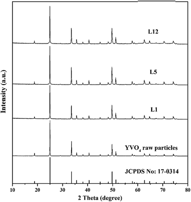 | ||
| Fig. 2 XRD patterns of YVO4:Eu3+ powders obtained after one, five, and 12 cycles of laser irradiation. | ||
Fig. 3 shows representative SEM images and the corresponding size distributions of raw particles and the as-synthesized YVO4:Eu3+ nanoparticles. The raw particles are clearly micron-sized and have irregular shapes with smooth surfaces. After one cycle of laser irradiation, nanoparticles with sizes less than 100 nm were clearly observed in the SEM image (L1). Note that only raw particles and nanoparticles less than 100 nm in size were observed in sample L1, and ablation craters were clearly observed after laser irradiation (Fig. S2†). After three cycles of irradiation, some larger nanoparticles were observed, and some spindle-shaped particles with sizes greater than 600 nm appeared after 12 cycles of irradiation (L12). The particles grew up regularly along the long-axis of the ovoid-like nanoparticles to become spindle-shaped, as shown in the SEM images from L5 to L12. To better understand the growth behaviors of YVO4:Eu3+ nanoparticles, detailed information about the size distributions of the produced nanoparticles was obtained by directly counting the numbers of particles in different areas of the copper grid. The particle size histograms of different samples were fit by log-normal functions, and the corresponding parameters are displayed in the right side of Fig. 3. Sample L1 has a narrow size distribution with a median diameter of 42.4 nm, which is almost same as that of L3. However, some ovoid-like nanoparticles with a larger particle size (≥200 nm) were observed in sample L3 in contrast with that in L1. The particle diameter gradually increased with increasing number of irradiation cycles, and the size distribution also became broader. For five or more cycles of irradiation, the mode of bimodal peaks with log-normal function fitting matched better than that of the single peak. It is worth mentioning that we observed spindle-like nanoparticles with sizes greater than 600 nm and nanoparticles smaller than 100 nm simultaneously in sample L12, indicating that small nanoparticles (the left tails of the log-normal fitting curves in Fig. 3) can still be produced after additional cycles of laser irradiation.
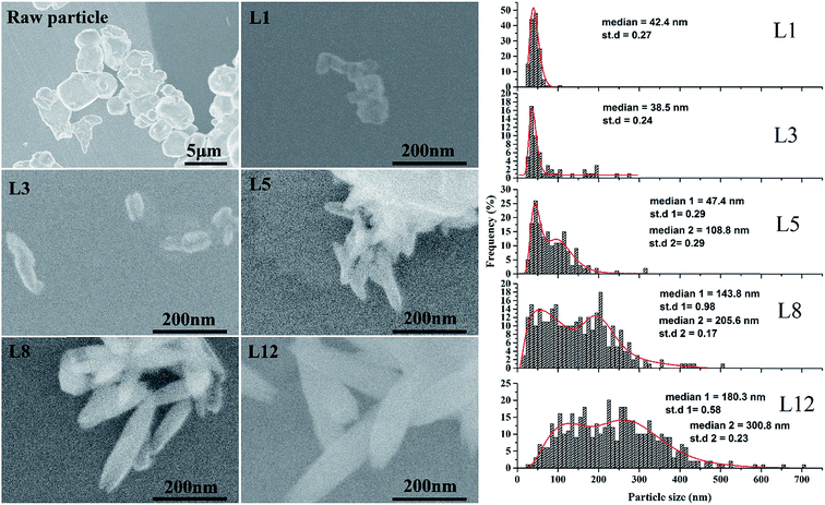 | ||
| Fig. 3 SEM images of YVO4:Eu3+ raw particles and nanoparticles obtained after one, three, five, eight and 12 cycles of laser irradiation and the corresponding size distribution. | ||
EDS elemental mapping was performed in the area marked by a rectangle in Fig. 4. The spindle-like and flower-like nanoparticles were again confirmed to be YVO4:Eu3+ crystals as they were enriched in Y, V, O, and Eu. All these elements were uniformly distributed in the particles, indicating the feasibility of fabricating lanthanide-doped oxide nanoparticles using this technique.
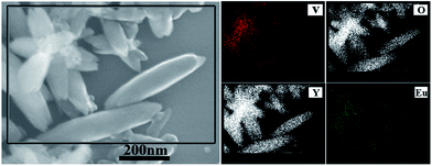 | ||
| Fig. 4 EDS elemental mapping of the area of sample L8 marked by the rectangle box of SEM image (left side). | ||
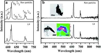
Fig. 5a shows PL properties of the raw particles and the as-prepared after laser irradiation for eight cycles (sample L8) excited at 280 nm. The shape of the curve is identical, and the absorption at UV wavelength is due to the charge transfer from the oxygen ligands to the central vanadium ions inside the VO43− groups. The emission curves show the peaks at 594, 619, 652 and 700 nm, corresponding to the 5D0–7FJ (J = 1, 2, 3, 4) transitions of the Eu3+ ions, respectively.24 No emission was observed from VO43−, indicating that the energy transfer from the VO43− groups to the Eu3+ ions is very efficient.24,34 The emission spectra are dominated by the red 5D0–7F2 transition because the host material has no inversion center (D2d symmetry).24,34 The emission, which is assigned to electric dipole transitions, splits into three components at 609, 615 and 619 nm because of the lowering of local site symmetry of Eu3+ ions.34 The CL curves of the raw particles and nanoparticles were collected to further confirm the optical properties of single nanoparticles (insets of Fig. 5b). The raw particles and spindle-like nanoparticles exhibited identical CL curves, confirming the purity of the phase of the YVO4:Eu3+ spindle-like nanoparticles. CL emission mapping was also conducted for two single nanoparticles, and the different colors in the nanoparticles illustrate different emission intensities. The strongest emission portion (white colour) was observed in the area of overlap between the two nanoparticles, and the weakest emission (blue colour) was observed at the nanoparticle edge. This could be attributed to the different emission volumes in the nanoparticles as well as to the dangling bonds surrounding Eu3+ ions at the nanoparticle surface, lead to weak emission intensity. The symmetrical emission color in CL maps indicates the good distribution of the Eu3+ dopant in the single nanoparticle produced by the laser irradiation from sequential flowing aqueous suspension. This result is consistent with that of the EDS results. However, the differences in relative peak intensity between the PL and CL spectra may be caused by the different measurement conditions and excitation mechanism.26
Based on our experimental results, the process of particle formation and growth can be described as follows. (I) When the surfaces of YVO4:Eu3+ raw particles are irradiated with the first pulsed laser beam, a plasma plume is induced immediately at the solid–liquid interface; an acoustic wave is created at a supersonic velocity, leading to an extra pressure in the plasma plume. (II) Primary nanocrystals are produced when the temperature and pressure of plasma plume quenching to phase-transition because of the confinement of the liquid. (III) Subsequently, the nanocrystals rapidly grow. Two mechanisms are typically involved in the process of nanocrystal growth in water. Ostwald ripening, is a classical mechanism in which smaller crystals dissolve and are redeposited onto larger particles because of the reduction in the driving force of surface energy with decreasing particle size.35 The second mechanism, oriented attachment, describes the self-assembly of adjacent nanoparticles that share a common crystallographic orientation; the overall energy of the system is reduced by the combination of these particles at a planar interface.36 In our case, oriented attachment was most likely to occur for two reasons. First, our previous results showed that the secondary nanoparticles obtained by conventional laser irradiation were composed of many primary nanocrystals.30 Second, crystal defects and boundaries were clearly observed in the high-resolution TEM (HR-TME) images.37 These findings were consistent with the features of nanoparticles formed via oriented attachment. In this study, the ovoid-like YVO4:Eu3+ nanoparticles were fabricated via the same mechanism observed in the previous study30 when the surface of YVO4:Eu3+ raw particles were irradiated by the pulsed laser. Importantly, the ovoid-like nanoparticles clearly grew as the suspension was irradiated for several cycles by the pulsed laser.
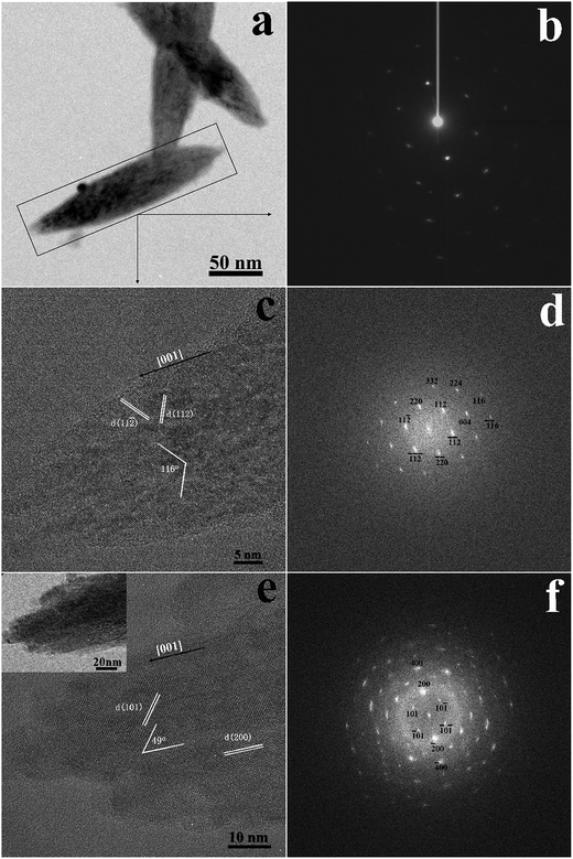
Fig. 6 shows TEM images after eight cycles of laser irradiation. The selected area electron diffraction pattern (Fig. 6b) of the area indicated by the rectangular box in Fig. 6a indicates that the spindle-like nanoparticle had a single-crystalline structure with high crystallinity. This is very important for phosphor materials because better crystallinity generally means fewer defects and stronger luminescence. As mentioned above, the nanoparticles grew longer with increasing number of irradiation cycles, and flower-like particles (Fig. S3†) were observed when the suspension was irradiated for five cycles or more. Here, the mechanism of particle growth would be different than that of the primary nanocrystals formed directly from the plasma plume. When the YVO4:Eu3+ suspension was irradiated for several cycles, most of the particles would be irradiated again. Therefore, on the one hand, new nanoparticles would be produced from the unreacted raw particles; on the other hand, the ovoid-like nanoparticles obtained in the initial laser irradiation process were heated for a short period again, the only way to generate large particles was for existing particles to merge with their neighbors, including the newly produced nanoparticles. This process led to a broad size distribution, as shown in the right side of Fig. 3. Therefore, growth was expected to occur through diffusion and coalescence. When the nanoparticles were heated by the laser energy, the kinetic energy of the atoms in nanoparticles increased accordingly38 giving the nanoparticles more energy to collide, merge, and grow.38 The increased temperature also encouraged the diffusion of atoms to minimize their surface tension. Finally, the ovoid-like nanoparticles merged and grew into a spindle-like nanoparticles. The existence of flower-like particle confirmed that the growth occurred through diffusion and coalescence, as the petals of flower-like particles were actually composed of spindle-like particles. Furthermore, we also considered the effect of aging time, because the particles would grow up along with different aging time at the room temperature in various cases such as in ref. 5. In our case, as the number of laser irradiation cycles increased, the aging time also increased, which might have influenced the particle growth. However, we found that the aging time was not an important factor in the growth of ovoid-like YVO4:Eu3+ in water; even the particle size remained unchanged after two weeks as the electric bilayer at the nanoparticle surface led to high stability. Therefore, during the process of diffusion and coalescence, the kinetic energy of the atoms provided by the laser must high enough to overcome the electrostatic repulsive force between nanoparticles.38,39 As the particle size distribution depicted in Fig. 3, the right-hand tail of the log-normal curves are attributed to the growth by diffusion and coalescence, whereas the left-hand side is attributed to growth via oriented attachment.
Fig. 6c and d show the HRTEM and fast Fourier transformation (FFT) of the area indicated by the rectangle in Fig. 6a. The clear lattice fringes in HRTEM image confirmed the high crystallinity of spindle-like nanoparticles. FFT result shows that the lattice fringes can be indexed (112) and (11![[2 with combining macron]](https://www.rsc.org/images/entities/char_0032_0304.gif) ) of tetragonal phase of YVO4, indicating that the zone axis of electron incidence is [
) of tetragonal phase of YVO4, indicating that the zone axis of electron incidence is [![[1 with combining macron]](https://www.rsc.org/images/entities/char_0031_0304.gif) 10]. The detailed indices of the crystal plane are displayed in FFT pattern, which was consistent with the 116° angle between the (112) and (11
10]. The detailed indices of the crystal plane are displayed in FFT pattern, which was consistent with the 116° angle between the (112) and (11![[2 with combining macron]](https://www.rsc.org/images/entities/char_0032_0304.gif) ) planes in the HRTEM image. Therefore, we deduce that the long axis of the spindle-like nanoparticle is most likely aligned along the [001] direction. To confirm this speculation, the structure of another particle is analyzed (Fig. 6e and f). The lattice fringes correspond to the (200) and (101) planes (Fig. 6e), and the 49° angle between these two planes matched the FFT pattern (Fig. 6f). These results confirmed the single-crystalline, tetragonal structure of the spindle-like nanoparticle, with [001] being the preferential growth direction.
) planes in the HRTEM image. Therefore, we deduce that the long axis of the spindle-like nanoparticle is most likely aligned along the [001] direction. To confirm this speculation, the structure of another particle is analyzed (Fig. 6e and f). The lattice fringes correspond to the (200) and (101) planes (Fig. 6e), and the 49° angle between these two planes matched the FFT pattern (Fig. 6f). These results confirmed the single-crystalline, tetragonal structure of the spindle-like nanoparticle, with [001] being the preferential growth direction.
In fact, the final shape of the single-crystalline mainly depends on the competitive growth of different crystallographic planes. YVO4 crystallizes in a zircon-type tetragonal crystal system with space group of I41/amd,24 and the growth is anisotropic since a = b ≠ c in the tetragonal system. The (100) plane is a more closely packed, thus, the growth of the (100) plane is slower than the growth of the (001) plane perpendicular to the growth direction, leading to a higher growth rate along [001] direction under appropriate thermodynamic conditions, such as in our experiments.40,41 Chow et al.41 reported that crystalline YVO4 grows preferentially along the c-axis when other growth conditions remained the same. Finally, the intrinsic anisotropy of tetragonal YVO4 and more reactive (001) surface result in more rapid growth along the c-axis, thereby forming nanorods.40 The sharp tips of the nanorods result in the spindle-like morphology and can be attributed to the insufficient supply of reactant resulting from the fast cooling speed at the late stage of the reaction. Importantly, the TEM results confirmed the growth direction. The in-depth mechanism should be further explored in the future.
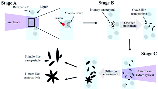
The entire process of the laser-induced particle growth is briefly summarized in Fig. 7. In stage A, the primary nanocrystals were produced from the high-density plasma plume when the surfaces of YVO4:Eu3+ raw particles were irradiated by the laser beam. In stage B, the primary nanocrystals rapidly grew into ovoid-like nanoparticles via oriented attachment mechanism. In stage C, when the suspension was subjected to additional cycles of pulsed laser irradiation, the ovoid-like nanoparticles grew via diffusion and coalescence into spindle-like single-crystalline along [001] direction and flower-like nanoparticles.
Conclusions
In summary, we have demonstrated a unique approach for the preparation of YVO4:Eu3+ nanoparticles by laser irradiation from a sequential flowing aqueous suspension in a free liquid reactor. Transmission electron microscopy result showed that spindle-like particles are single-crystalline, and strong light emission even from a single particle was confirmed by cathodoluminescence mapping. Ovoid-like nanoparticles were obtained via the oriented attachment of the primary nanocrystals produced from the plasma plume when the surfaces of raw particles were irradiated by the pulsed laser beam. The ovoid-like nanoparticle grew along the [001] direction to form spindle-like single-crystalline when subjected to additional cycles of laser irradiation. Spindle-like and flower-like nanoparticles were formed via the diffusion and coalescence of ovoid-like nanoparticle after several cycles of laser irradiation.Acknowledgements
The authors gratefully thank Prof. Nakamura, and Mr Iida at Tokyo Tech. This study was supported by Kazuchika Okura Memorial Foundation, the Chinese Scholarship Council (CSC), the Collaborative Research Project of Materials & Structures Laboratory (Tokyo Tech.), and the Center for Advanced Materials Analysis (Tokyo Tech.).References
- J. Zhang, G. Chen, D. Guay, M. Chaker and D. Ma, Nanoscale, 2014, 6, 2125–2130 RSC.
- P. Russo, A. Hu, G. Compagnini, W. W. Duley and N. Y. Zhou, Nanoscale, 2014, 6, 2381–2389 RSC.
- V. Amendola and M. Meneghetti, Phys. Chem. Chem. Phys., 2013, 15, 3027–3046 RSC.
- G. Yang, Prog. Mater. Sci., 2007, 52, 648–698 CrossRef CAS.
- J. Liu, C. Liang, G. Xu, Z. Tian, G. Shao and L. Zhang, Nano Energy, 2013, 2, 328–336 CrossRef CAS.
- J. Liu, C. Liang, H. Zhang, Z. Tian and S. Zhang, J. Phys. Chem. C, 2012, 116, 4986–4992 CAS.
- Z. Tian, C. Liang, J. Liu, H. Zhang and L. Zhang, J. Mater. Chem., 2011, 21, 18242–18247 RSC.
- A. Fojtik and A. Henglein, Ber. Bunsen-Ges., 1993, 97, 252–254 CrossRef CAS.
- H. Usui, Y. Shimizu, T. Sasaki and N. Koshizaki, J. Phys. Chem. B, 2005, 109, 120–124 CrossRef CAS PubMed.
- H. Wang, A. Pyatenko, K. Kawaguchi, X. Li, Z. Swiatkowska-Warkocka and N. Koshizaki, Angew. Chem., Int. Ed., 2010, 49, 6361–6364 CrossRef CAS PubMed.
- H. Wang, N. Koshizaki, L. Li, L. Jia, K. Kawaguchi, X. Li, A. Pyatenko, Z. Swiatkowska-Warkocka, Y. Bando and D. Golberg, Adv. Mater., 2011, 23, 1865–1870 CrossRef CAS PubMed.
- Y. Ishikawa, Q. Feng and N. Koshizaki, Appl. Phys. A, 2010, 99, 797–803 CrossRef CAS.
- P. Wagener and S. Barcikowski, Appl. Phys. A, 2010, 101, 435–439 CrossRef CAS.
- P. Wagener, M. Lau, S. Breitung-Faes, A. Kwade and S. Barcikowski, Appl. Phys. A, 2012, 108, 793–799 CrossRef CAS.
- M. Lau and S. Barcikowski, Appl. Surf. Sci., 2015, 348, 22–29 CrossRef CAS.
- M. Lau, A. Ziefuss, T. Komossa and S. Barcikowski, Phys. Chem. Chem. Phys., 2015, 17, 29311–29318 RSC.
- F. Wang and X. Liu, Chem. Soc. Rev., 2009, 38, 976–989 RSC.
- F. Wang and X. Liu, J. Am. Chem. Soc., 2008, 130, 5642–5643 CrossRef CAS PubMed.
- F. Wang, R. Deng, J. Wang, Q. Wang, Y. Han, H. Zhu, X. Chen and X. Liu, Nat. Mater., 2011, 10, 968–973 CrossRef CAS PubMed.
- F. Wang, X. Xue and X. Liu, Angew. Chem., Int. Ed., 2008, 47, 906–909 CrossRef CAS PubMed.
- C. Li and J. Lin, J. Mater. Chem., 2010, 20, 6831–6847 RSC.
- S. Gai, C. Li, P. Yang and J. Lin, Chem. Rev., 2013, 114, 2343–2389 CrossRef PubMed.
- Z. Xu, C. Li, P. Yang, C. Zhang, S. Huang and J. Lin, Cryst. Growth Des., 2009, 9, 4752–4758 CAS.
- C. Brecher, H. Samelson, A. Lempicki, R. Riley and T. Peters, Phys. Rev., 1967, 155, 178 CrossRef CAS.
- Z. Hou, P. Yang, C. Li, L. Wang, H. Lian, Z. Quan and J. Lin, Chem. Mater., 2008, 20, 6686–6696 CrossRef CAS.
- Z. Xu, X. Kang, C. Li, Z. Hou, C. Zhang, D. Yang, G. Li and J. Lin, Inorg. Chem., 2010, 49, 6706–6715 CrossRef CAS PubMed.
- E. Beaurepaire, V. Buissette, M.-P. Sauviat, D. Giaume, K. Lahlil, A. Mercuri, D. Casanova, A. Huignard, J.-L. Martin and T. Gacoin, Nano Lett., 2004, 4, 2079–2083 CrossRef CAS.
- D. Casanova, C. Bouzigues, T.-L. Nguyen, R. O. Ramodiharilafy, L. Bouzhir-Sima, T. Gacoin, J.-P. Boilot, P.-L. Tharaux and A. Alexandrou, Nat. Nanotechnol., 2009, 4, 581–585 CrossRef CAS PubMed.
- J.-B. Masson, D. Casanova, S. Türkcan, G. Voisinne, M.-R. Popoff, M. Vergassola and A. Alexandrou, Phys. Rev. Lett., 2009, 102, 048103 CrossRef PubMed.
- H. Wang, O. Odawara and H. Wada, Sci. Rep., 2016, 6 DOI:10.1038/srep20507.
- X. Lin, P. Liu, J. Yu and G. Yang, J. Phys. Chem. C, 2009, 113, 17543–17547 CAS.
- C.-C. Huang, C.-S. Yeh and C.-J. Ho, J. Phys. Chem. B, 2004, 108, 4940–4945 CrossRef CAS.
- C. He, T. Sasaki, Y. Shimizu and N. Koshizaki, Appl. Surf. Sci., 2008, 254, 2196–2202 CrossRef CAS.
- K. Riwotzki and M. Haase, J. Phys. Chem. B, 1998, 102, 10129–10135 CrossRef CAS.
- H. Zhang, C. Liang, Z. Tian, G. Wang and W. Cai, CrystEngComm, 2011, 13, 1063–1066 RSC.
- R. L. Penn and J. F. Banfield, Science, 1998, 281, 969–971 CrossRef CAS PubMed.
- H. Wang, O. Odawara and H. Wada, J. Alloys Compd., 2016, 683, 1–6 CrossRef CAS.
- P. Boyer and M. Meunier, J. Phys. Chem. C, 2012, 116, 8014–8019 CAS.
- B. Gökce, D. D. van't Zand, A. Menéndez-Manjón and S. Barcikowski, Chem. Phys. Lett., 2015, 626, 96–101 CrossRef.
- H. Deng, C. Liu, S. Yang, S. Xiao, Z.-K. Zhou and Q.-Q. Wang, Cryst. Growth Des., 2008, 8, 4432–4439 CAS.
- K. Chow and H. McKnight, Mater. Res. Bull., 1973, 8, 1343–1350 CrossRef CAS.
Footnote |
| † Electronic supplementary information (ESI) available. See DOI: 10.1039/c6ra28118d |
| This journal is © The Royal Society of Chemistry 2017 |

