 Open Access Article
Room-temperature pulsed CVD-grown SiO2 protective layer on TiO2 particles for photocatalytic activity suppression
Jing Guo ab,
Shaojun Yuana,
Yangyang Yua,
J. Ruud van Ommenb,
Hao Van Buib and
Bin Liang*a
aMulti-phase Mass Transfer & Reaction Engineering Lab, College of Chemical Engineering, Sichuan University, Chengdu 610065, China. E-mail: liangbin@scu.edu.cn; Fax: +86-28-85460556; Tel: +86-28-85460556
bDepartment of Chemical Engineering, Delft University of Technology, Delft, The Netherlands
First published on 16th January 2017
Abstract
This work presents a novel chemical vapor deposition (CVD) approach that enables the deposition of ultrathin and conformal SiO2 layers on TiO2 anatase nanoparticles at room temperature using SiCl4 and air containing water without the use of a catalyst. The morphology of the CVD-grown SiO2 layers was found to be strongly dependent on the initial surface states of the TiO2 nanopowders, which could be altered by applying a simple heat pretreatment. The deposition on untreated TiO2 resulted in granular films, whereas on preheated TiO2 highly uniform and conformal SiO2 layers were obtained. By varying the SiCl4 precursor dosing time and the number of CVD cycles, the thickness of the SiO2 could be controlled at the nanometer level, which allowed us to investigate the influence of film thickness on the photocatalytic suppression ability. We found that a conformal SiO2 layer with a thickness of 3 nm could sufficiently suppress the photocatalytic activity of anatase TiO2 nanoparticles, which was demonstrated by the photodegradation of Rhodamine B. Our approach offers a simple, fast, feasible and low-temperature deposition method which can be directly applied to SiO2 coating on nanoparticles in pigments and other fields, particularly heat-sensitive materials, and further developed for large-scale production.
1 Introduction
Nanoparticulate titanium dioxide (TiO2) is the most commonly-used white pigment in the paint, plastic, and paper industries due to its high brightness, high refractive index and photostability.1,2 However, the high photocatalytic activity of TiO2 facilitates the oxidation and decomposition of organic compounds, for instance, in the paint layer, which consequently changes the color and severely decreases the lifetime of the products.3 Therefore, in these practical applications, TiO2 nanoparticles (NPs) are commonly coated with a thin insulating layer to suppress their photocatalytic activity. On the one hand, this coating layer is required to sufficiently block the transport of electrons and holes, which are generated in the TiO2 particles under UV-light irradiation, to the surface that initiates the photocatalytic reactions with organic compounds. On the other hand, the coating layer must not affect the bulk optical properties of the TiO2 pigment. Owing to their large band gap, high thermal and optical stabilities, and chemical inertness, ceramic oxides, such as Al2O3, SiO2, CeO2 and ZrO2, have been popularly used as coating materials on TiO2 for photocatalytic suppression.4–14Various strategies have been developed to deposit thin metal oxide films on TiO2 pigment particles. Among them, wet chemistry methods, such as sol–gel and precipitation, have been extensively used due to their simplicity, inexpensiveness and versatility in producing various materials with tunable properties.4–6,8,15,16 For instance, Ren et al. employed sol–gel method in the presence of 3-hydroxytyramine hydrochloride, poly(diallyldimethylammonium chloride), poly(sodium 4-styreneslfonate), tetraethyl orthosilicate (TEOS) and solvents to fabricate TiO2/SiO2 core/shell particles.6 Upon exposure to UV radiation, a rattle-type structure with tunable catalytic/UV-shielding properties was obtained. The TiO2/SiO2 core/shell structure for UV radiation shielding can also be obtained by the conventional Stöber method using TEOS and solvents such as ethanol, NH4OH and acetone.4,5 Binary Al2O3/SiO2 coating layers have been deposited on TiO2 nanoparticles using sol–gel and precipitation mothods for enhanced brightness and whiteness of TiO2.8,16 Moreover, wet chemistry methods enable the deposition of various ceramic and transition metal oxide materials such as ZrO2, CeO2, NiO and CoO on TiO2 particles.15 Nevertheless, these methods have several shortcomings in controlling the coating thickness and conformality due to their high sensitivity to experimental parameters, such as precursor concentration, type and pH of the solvents, deposition time and temperature. In addition, these methods are time consuming and normally require post-treatment processes, for instance, high temperature treatment, washing, drying, and separation to eliminate impurities that arise from the residual solvent and reaction byproducts.5,6 These disadvantages hinder the applicability of wet chemistry in the syntheses of metal oxide layers on TiO2 in practical applications. It is therefore of importance to search for a facile, low-cost, and efficient approach for deposition of metal oxide layers on the TiO2 particles.
Gas-phase deposition techniques such as chemical vapor deposition (CVD) and atomic layer deposition (ALD) have been attractive alternatives in recent years. ALD is based on the sequential exposures of the support/substrate to precursors in the gas phase. This enables self-limiting surface reactions and provides the ability to control the amount of depositing materials down to atomic level with high uniformity and conformality in many applications.17,18 ALD has also been applied for coating Al2O3 and SiO2 films on TiO2 nanoparticles for catalytic suppression.12–14 With ALD, ultrathin and conformal SiO2 and Al2O3 layers with a thickness of several nanometers can be achieved, showing excellent stability and high efficiency in suppressing the catalytic properties of TiO2 nanoparticles.12,13 Molecular layer deposition (MLD), the organic counterpart of ALD, has also been applied for depositing aluminum alkoxide (i.e., alucone) using trimethylaluminum and ethylene glycol as precursors. This alucone layer can reduce the undesired color change of the white pigment TiO2, which was observed for the TiO2 coated with SiO2 and Al2O3 layers by ALD.14
CVD of SiO2 thin films has been extensively investigated over the past decades.10,11,19–25 TEOS, silane (SiH4), dichlorosilane (SiCl2H2) and silicon tetrachloride (SiCl4) are among the most popularly used precursors in conjunction with H2O or O2 as oxidizing agent. This has been used to deposit thin SiO2 layers on TiO2 micro- and nanoparticles.10,23,26,27 Powell et al. demonstrated CVD of SiO2 films at a temperature in the range of 1300–1500 °C employing the SiCl4/O2 chemistry, and found that the film surface was smoother at a higher temperature and in the absence of water.11,26,27 Using the same SiCl4/O2 chemistry, Simpson et al. reported that ultrathin and continuous SiO2 layers with a thickness of 1–2 nm could be obtained at 1000 °C.10 By replacing O2 with H2O as the oxidizing agent, Tsapatsis and Gavalas demonstrated that the deposition temperature of SiO2 CVD could be significantly reduced to approximately 600 °C.23 It can be concluded that CVD of SiO2 generally requires an elevated temperature. Remarkably, Klaus and George found that the use of NH3 as catalyst for the SiCl4/H2O CVD process could enable the deposition of SiO2 at room temperature.24 To the best of our knowledge, this is so far the only room-temperature SiO2 CVD process using SiCl4 precursor reported in literature.
Accordingly, the main aim of this work is to develop a novel approach that enables the room-temperature CVD (RTCVD) of SiO2. We demonstrate that ultrathin and conformal SiO2 layers on TiO2 nanoparticles can be deposited at room temperature using SiCl4 and air containing water without the use of catalysts. As SiCl4 can react robustly with H2O, the use of air containing water is to decelerate the reaction kinetics and achieve a better control of deposition rate. Therefore, the thickness of coating layers can be controlled at nanometer scale by varying the SiCl4 dosing time and the number of CVD cycles. We found that the morphology of the coating layers, i.e., granular or continuous films, is strongly influenced by initial surface states of the TiO2 nanopowders, which can be altered by applying a simple heat treatment at a relatively low temperature (i.e., 170 °C). Photocatalytic tests are performed on the as-synthesized SiO2/TiO2 nanoparticles to evaluate the catalytic suppression ability of the room-temperature CVD-grown SiO2, and to study the influence of coating thickness on the suppression ability. The results obtained from our work demonstrate a simple, fast and feasible method for coating SiO2 on TiO2 pigment, which is applicable for other powders and can be further developed for large-scale production.
2 Experimental
2.1. Materials
Anatase TiO2 powders with diameter in the range of 200–300 nm and specific surface area of about 10.7 m2 g−1 (determined by BET technique) were provided by Taihai TiO2 pigment Co. (Panzhihua, China). Rhodamine B (RhB) and silicon tetrachloride (SiCl4) were purchased from Sigma-Aldrich (St. Louis, MO, USA). The TiO2 powders and the chemicals were used as received without any additional treatment or purification.2.2. Preparation of SiO2-coated TiO2 nanoparticles
The coating apparatus and deposition steps are schematically shown in Fig. 1. TiO2 powders, without or with heat pretreatment at 170 °C for 1 h (i.e., performed ex situ in an oven prior to the CVD), were supported on a porous distributor plate, and were immobilized inside a glass reactor with volume of 1 L (Fig. 1a). The thickness of the TiO2 layer on the distributor plate is about 2 mm. At this thickness and with a long dosing time (i.e., up to 60 min), the diffusion limitation of the gas molecules to the bottom of the layer can be eliminated.28 Before introducing SiCl4, the reactor was slowly evacuated to a pressure of 70 mbar using a mechanical pump. This was to create a pressure difference between the chamber and the SiCl4 vapor precursor (ca. 260 mbar at room temperature). SiCl4 was then fed into the reactor (V1 opened, V2 and V3 closed) with dosing times varying from 3 to 60 min to react with the hydroxyl groups (–OH) on the surface of TiO2 nanoparticles (Fig. 1b–d). Hereafter, the excess precursor, if any, and the reaction byproducts (i.e., HCl) were removed (V1 and V2 closed, V3 opened). Air containing H2O vapor (i.e., 44% RH) was then introduced into the chamber and maintained at atmospheric pressure to react with the Si–Cl terminated surface, forming an SiO2 layer and creating an –OH terminated surface (Fig. 1e), which is necessary for the chemisorption of SiCl4 in the next cycle. The use of air containing H2O vapor instead of pure H2O is due to the fact that SiCl4 can react robustly with H2O, which could lead to the uncontrollable deposition.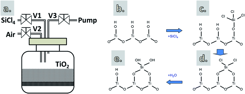 | ||
| Fig. 1 A schematic drawing of the reactor (a) and the proposed growth mechanism of SiO2 using SiCl4 and H2O vapor (b–e). | ||
2.3. Material characterization
The thickness of the SiO2 layers on the TiO2 particles was measured by transmission electron microscopy (TEM) using a JEOL JEM1400 operating at a voltage of 120 kV and a current density of 50 pA cm−2. The composition of the SiO2 layers was characterized by X-ray photoelectron spectroscopy (XPS) (XSAM800, Kratos, UK) with monochromatized Al Kα radiation at constant dwell time of 100 ms and pass energy of 55 eV. The peaks positions were calibrated according to the C 1s peak at 284.8 eV. The infrared spectra were acquired using FTIR spectroscopy (Spectrum II L1600300 spectrometer, PerkinElmer) in transmission mode.2.4. Photocatalytic activity determination
The photocatalytic activity of the SiO2-coated TiO2 powders was evaluated by the photodegradation of RhB solution. For each test, 150 mg powders were added to 30 mL RhB solution (concentration of 9 mg L−1) and continuously stirred in the dark for 30 min to obtain a uniform suspension. Thereafter, the suspension was exposed to UV radiation generated by a mercury lamp with a power of 300 W or 500 W for different exposure times. The set-up allowed to carry out up to 10 samples simultaneously, which ensured that all samples were irradiated under the same conditions, such as light intensity, exposure time, and temperature. The suspension was then centrifuged to separate the powders from the solution. Finally, the solution was analyzed by UV-visible spectrophotometry to determine the residual concentration of the RhB in solution, which was used to evaluate the catalytic activity suppression of the SiO2 layers.3 Results and discussion
3.1. Reaction mechanism
The chemical reactions in CVD of SiO2 using SiCl4 and H2O are generally described as:24| SiCl4 + 2H2O → SiO2 + 4HCl | (1) |
However, it has been reported that the actual growth of SiO2 CVD consists of a number of reactions, which can be divided into homogeneous and heterogeneous reactions.22,23 Homogeneous reactions occur between SiCl4 and H2O molecules in the gas phase, forming oligomers or particles. These reactions have slow kinetics.22,23,29 The heterogeneous reactions take place directly on the surface via substitution reactions of surface groups (i.e., –Cl and –OH groups). In this case, the reactions are described as:22,23
| |–OH(s) + SiCl4(g) → |–O–Si–Cl(s) + HCl(g) | (2) |
| |–O–Si–Cl(s) + H2O(g) → |–O–Si–OH(s) + HCl(g) | (3) |
| |–O–Si–OH(s) + |–O–Si–Si–OH(s) → Si–O–Si(s) + H2O(g) | (4) |
| |–O–Si–OH(s) + |–O–Si–Si–Cl(s) → Si–O–Si(s) + HCl(g) | (5) |
Therefore, CVD of SiO2 using SiCl4 and H2O might consist of gas-phase reactions, substitution reactions of surface functional groups and condensation reactions.
3.2. Morphology and composition of the coating layers
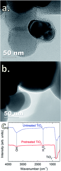
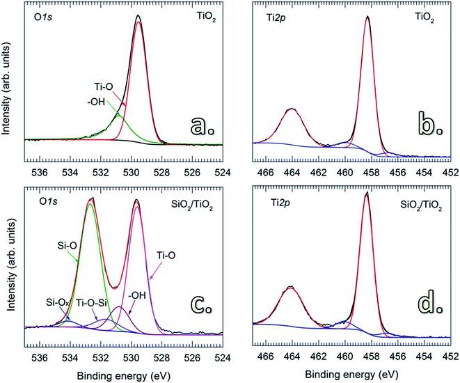
Tsapatsis et al. postulated that the surface morphology of the coating layer is influenced by the reactant species, i.e., H2O molecules (vapor and physisorbed H2O) and –OH groups (chemisorbed H2O). Accordingly, the reactions between SiCl4 and H2O molecules may lead to the formation of a granular surface.22,23 However, this has not been experimentally demonstrated. Here, we observed that the deposition of SiO2 on TiO2 particles without pretreatment resulted in granular and porous surfaces (Fig. 2a). This is attributed to the presence of a thick hydration shell with abundant physisorbed H2O and –OH groups on the particle surface,30 as detected by FTIR spectra (Fig. 2c). The peak at 3400 cm−1 is attributed to the stretching vibration of –OH groups (νO–H) on the surface of TiO2 particles, whereas the peak at 1625 cm−1 corresponds to the bending vibration of physisorbed H2O molecules (δH2O).31,32 In the fingerprint region (i.e., wavenumber below 1000 cm−1), the peaks located in the wavenumber range of 500–700 cm−1 are ascribed to the bending vibration of Ti–O–Ti (δTi–O–Ti) of the TiO2 particles.31 Upon the heat pretreatment of TiO2 particles at 170 °C for 1 h, the intensity of the characteristic peaks of νO–H and δH2O significantly decreases (Fig. 2c), indicating that a large amount of the physisorbed H2O molecules and –OH groups has desorbed from the TiO2 surface.33–37 Therefore, for the untreated TiO2 particles, the physisorbed H2O can react with SiCl4 to form SiO2 following reaction (1), and in accordance with the previous assumption by Tsapatsis et al., a granular film is formed.22 In comparison with the previous findings that the reaction between SiCl4 and H2O either required high temperatures22 or the presence of catalysts to enable the deposition at room temperature,24 our work has demonstrated the deposition of SiO2 at room temperature without the use of catalyst. This is probably due to the higher pressure range in the reactor, as well as the catalytic TiO2 surface. Klaus and George also observed that increasing H2O partial pressure resulted in the enhanced deposition of SiO2 in SiCl4/H2O CVD.24 Nevertheless, this requires further studies to verify, which is out of the scope of this work. On the pretreated TiO2 particles, highly uniform, continuous and dense SiO2 films are formed (Fig. 2b), which is substantially different from the porous and granular SiO2 films on the untreated TiO2 particles. This is ascribed to the different reaction mechanism. CVD of SiO2 on the pretreated TiO2 particles proceeds following the reactions (2)–(5) (i.e., via surface reactions with |–OH and |–Cl groups), thus resulting in the formation of continuous and dense layers.Fig. 3 shows the O 1s and Ti 2p core-level XPS spectra of uncoated and SiO2-coated TiO2 powders. For the uncoated TiO2, the O 1s spectrum is fitted to two peaks with binding energies (BE) at 529.5 and 530.8 eV (Fig. 3a) corresponding to the O–Ti and O–H chemical states, respectively.38 This is consistent with the results obtained from FTIR shown in Fig. 2c. The O 1s spectrum of the SiO2-coated TiO2 shows a noticeable difference with an intense peak at 532.69 eV, representing the Si–O chemical state in SiO2.39 The fitted spectrum also reveals the presence of additional components located at 534.5 eV (Si–Ox) and 531.64 eV (Si–O–Ti).39 No significant change was observed for the Ti 2p spectra of uncoated and SiO2-coated TiO2 particles. In addition, no considerable amount of Cl contamination was detected by XPS, suggesting the complete consumption of –Cl by the chemical reactions with H2O.
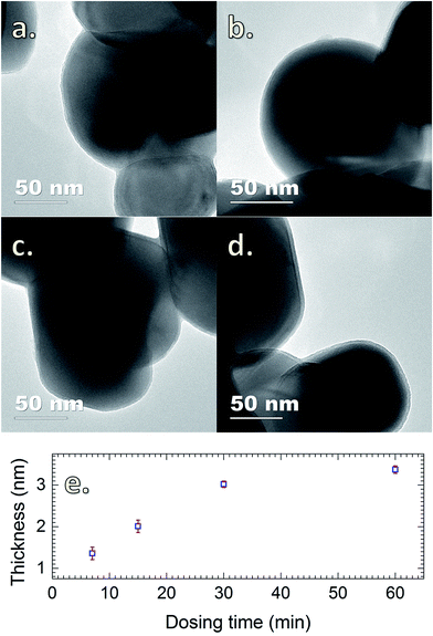
The presence of SiO2 is additionally confirmed by the FTIR spectra obtained for TiO2 powders coated with SiO2 layers with different SiCl4 dosing times (Fig. 4). The characteristics of SiO2 are represented by the two sharp peaks at 1227 and 1080 cm−1.5 The results show that the absorption increases drastically with the increase of SiCl4 dosing time from 3 to 30 min, which is indicative of the increase of the coating thickness consistent with the results obtained from TEM (Fig. 5). The images indicate that highly uniform and conformal SiO2 layers with a thickness as thin as 1 nm can be achieved, which is commonly difficult to obtain by conventional CVD. With increasing dosing time from 7 to 30 min, the coating thickness rises rapidly from 1.4 to 3.0 nm, and gradually reaches saturation with the further increase of dosing time. This saturation may be caused by the complete consumption of the –OH functional groups and adsorbed H2O on the surface by SiCl4, which consequently terminates the chemical reactions. A small increase in thickness with increasing dosing time from 30 to 60 min is attributed to the contribution of the residual H2O vapor inside the chamber and the condensation reactions described above (i.e., reactions (4) and (5)).
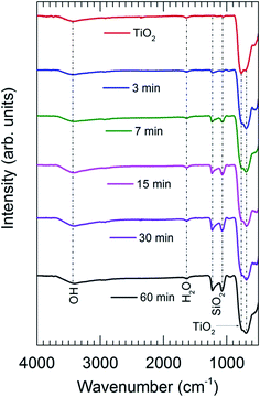 | ||
| Fig. 4 FTIR spectra of the uncoated TiO2 and SiO2-coated TiO2 with different SiCl4 dosing times. CVD was performed on pretreated TiO2 particles with an air exposure time of 60 min. | ||
3.3. Catalytic suppression of SiO2 coating layers
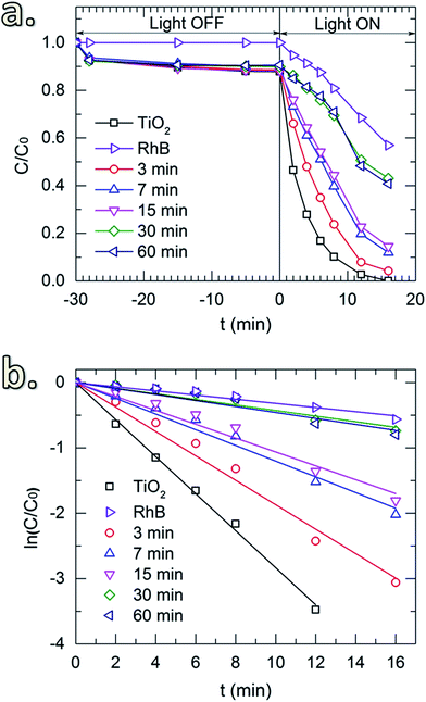
Fig. 6a shows the photocatalytic activity toward the degradation of RhB of the uncoated TiO2 and the TiO2 coated with SiO2 layers obtained for different SiCl4 dosing times. Prior to the UV irradiation, the solution was constantly stirred in the dark (light-off stage) for 30 min to obtain uniform particle dispersion. The samples were collected after certain time-intervals to determine the concentration of the remaining RhB. In the absence of TiO2 powders, the results show that during this stage, the concentration of RhB remained unchanged. However, a small drop of RhB concentration was observed for the solutions with TiO2 powders (both uncoated and coated with SiO2). This drop is caused by the adsorption of a fraction of RhB molecules on the surface of the particles. Thereafter, upon the exposure to UV radiation (light-on stage), the concentration of RhB decayed rapidly for the uncoated powders, indicating the high photocatalytic activity of TiO2. Similar effects were observed for the TiO2 coated with SiO2 deposited with short SiCl4 dosing times (up to 15 min). This could be due to the insufficient thickness of the coating and/or the devoid pin-hole free films. As shown in Fig. 5a and b, the thickness of the SiO2 layers for short dosing times is 2 nm or less (i.e., 1.4 and 2.0 nm for 7 and 15 min of dosing time, respectively). SiO2 films with a thickness of 3 nm and thicker obtained for longer SiCl4 dosing times showed significant improvement in the suppression of TiO2 photocatalytic activity. The small decrease in RhB concentration observed for these two powders (i.e., with SiO2 layers obtained for 30 and 60 min SiCl4 exposures) is nearly identical to the decrease observed for RhB without powders, which is attributed to the self-degradation of RhB under the UV irradiation. This is better indicated by the reaction kinetic plots shown in Fig. 6b obtained from the kinetic equation described as:40
ln(C0/C) = kappt, or C = C0![[thin space (1/6-em)]](https://www.rsc.org/images/entities/char_2009.gif) exp(−kappt) exp(−kappt)
| (6) |
| Dosing time/min | kapp/min−1 | R2 of fitting |
|---|---|---|
| 0 (uncoated TiO2) | 0.283 ± 0.004 | 0.99 |
| 3 | 0.187 ± 0.006 | 0.99 |
| 7 | 0.120 ± 0.005 | 0.99 |
| 15 | 0.106 ± 0.005 | 0.98 |
| 30 | 0.043 ± 0.003 | 0.97 |
| 60 | 0.046 ± 0.004 | 0.95 |
| RhB (without powders) | 0.032 ± 0.002 | 0.98 |
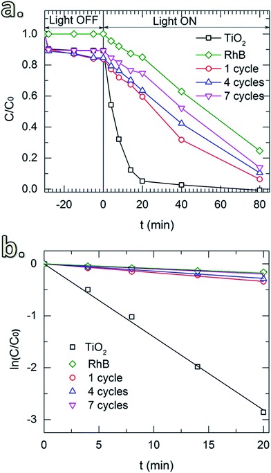
Fig. 7 shows the RhB degradation of the SiO2-coated TiO2 with different numbers of coating cycles. In this case, an SiCl4 dosing time of 30 min was applied for all of the depositions. Samples for 1, 4 and 7 cycles were tested. In addition, the UV irradiation power was reduced to 300 W to enable the study of the degradation up to 80 min. The same drop of RhB concentration caused by the surface adsorption was observed in the light-off stage (Fig. 7a). In the light-on stage, the reaction kinetic plots (Fig. 7b) show negligible effect of thickness on the photocatalytic degradation, demonstrating the sufficient suppression of the SiO2 layers deposited with a small number of CVD cycles. In comparison with the materials and coating methods that have been used to mitigate the photocatalytic activity of TiO2 pigmentary materials (Table 2), our approach showed several advantages in providing a fast, simple and efficient process. Especially, for the first time in literature a room-temperature gas-phase deposition technique for pigmentary coating applications is introduced.
| TiO2 material | Coating method | Coating material | Coating thickness (nm) | Deposition temperature (°C) | Photocatalytic reaction | Ref. |
|---|---|---|---|---|---|---|
| P25 | ALD | Al2O3 | 6 | 177 | Methylene blue | 41 |
| Anatase | ALD | SiO2 | 2 | 500 for SiO2 | IPA to acetone | 12 |
| SiO2/Al2O3 | 1/1 | 177 for Al2O3 | ||||
| SiO2/Al2O3/SiO2/Al2O3 | 0.5/0.5/0.5/0.5 | |||||
| P25 | ALD | Al2O3 | 3.8 | 150 | RhB | 42 |
| Anatase | ALD | SiO2 | 6 | 175 | Methylene blue | 13 |
| P25 | 9 | |||||
| Anatase | MLD | Alucone | 7–10 | 100–160 | Methylene blue | 14 |
| Rutile | CVD | SiO2 | 1–2 | 900–1000 | Methylene blue | 10 |
| Rutile | Wet-chemistry | ZrO2 | 5 | 40 | RhB | 15 |
| CeO2 | 1–2 | 60 | ||||
| Rutile | Wet-chemistry | CeO2 | 1–2 | 60 | RhB | 43 |
| ST-21 | Wet-chemistry | SiO2 | 4 | 40 | Methylene blue | 4 |
| P25 | Wet-chemistry | Porous SiO2 | 20 | Room temperature | RhB | 6 |
| Anatase | Pulsed-CVD | SiO2 | 3 | Room temperature | RhB | This work |
4 Conclusions
We have demonstrated the room-temperature pulsed-CVD of SiO2 thin films on TiO2 nanoparticles using SiCl4 as the Si precursor and air containing water vapor as the oxidizing agent without the use of catalysts. The formation of SiO2 was confirmed by XPS and FTIR spectroscopy. The deposition on the TiO2 powders without preheating resulted in a granular surface, whereas on pretreated TiO2 (at 170 °C for 1 h) highly uniform, conformal and continuous SiO2 films were obtained. The thickness of the SiO2 layer increased with SiCl4 dosing time and reached saturation most likely upon the consumption of the surface hydroxyl groups and water vapor. This enabled the control of coating thickness at nanometer level precision, and consequently, the study of the influence of film thickness on photocatalytic suppression ability of SiO2 films. Accordingly, we found that a minimum thickness of about 3 nm is needed to sufficiently suppress the photocatalytic properties of TiO2 toward the degradation of RhB. A further increase in film thickness resulted in only insignificant improvement in the suppression performance. Our work has demonstrated a simple, fast and feasible method for depositing SiO2 on TiO2 pigment at room temperature, which is applicable also for other powders, especially for heat-sensitive materials, and can be further developed for large-scale production.Acknowledgements
The authors would like to acknowledge the financial support of key project of National Natural Science Foundation of China (No. 21236004), and China Scholarship Council.References
- H. Shi, R. Magaye, V. Castranova and J. Zhao, Part. Fibre Toxicol., 2013, 10, 15–47 CrossRef CAS PubMed
.
- C. L. Bianchi, C. Pirola, F. Galli, G. Cerrato, S. Morandi and V. Capucci, Chem. Eng. J., 2015, 261, 76–82 CrossRef CAS
.
- X. Feng, S. Zhang and X. Lou, Colloids Surf., B, 2013, 107, 220–226 CrossRef CAS PubMed
.
- H. Lee, S. Koo and J. Yoo, J. Ceram. Process. Res., 2012, 13, S300–S303 Search PubMed
.
- O. K. Park and Y. S. Kang, Colloids Surf., A, 2005, 257, 261–265 CrossRef
.
- Y. Ren, M. Chen, Y. Zhang and L. Wu, Langmuir, 2010, 26, 11391–11396 CrossRef CAS PubMed
.
- Y. Liu, C. Ge, M. Ren, H. Yin, A. Wang, D. Zhang, C. Liu, J. Chen, H. Feng and H. Yao, Appl. Surf. Sci., 2008, 254, 2809–2819 CrossRef CAS
.
- Y. Zhang, H. Yin, A. Wang, M. Ren, Z. Gu, Y. Liu, Y. Shen, L. Yu and T. Jiang, Appl. Surf. Sci., 2010, 257, 1351–1360 CrossRef CAS
.
- H.-X. Wu, T.-J. Wang and Y. Jin, Ind. Eng. Chem. Res., 2006, 45, 5274–5278 CrossRef CAS
.
- D. J. Simpson, A. Thilagam, G. P. Cavallaro, K. Kaplun and A. R. Gerson, Phys. Chem. Chem. Phys., 2011, 13, 21132–21138 RSC
.
- Q. H. Powell, T. T. Kodas and B. M. Anderson, Chem. Vap. Deposition, 1996, 2, 179–181 CrossRef CAS
.
- D. M. King, X. Liang, B. B. Burton, M. K. Akhtar and A. W. Weimer, Nanotechnology, 2008, 19, 255604–255611 CrossRef PubMed
.
- X. Liang, K. S. Barrett, Y.-B. Jiang and A. W. Weimer, ACS Appl. Mater. Interfaces, 2010, 2, 2248–2253 CAS
.
- X. Liang and A. W. Weimer, J. Nanopart. Res., 2010, 12, 135–142 CrossRef CAS
.
- B.-X. Wei, L. Zhao, T.-J. Wang, H. Gao, H.-X. Wu and Y. Jin, Adv. Powder Technol., 2013, 24, 708–713 CrossRef CAS
.
- B.-X. Wei, L. Zhao, T.-J. Wang and Y. Jin, Ind. Eng. Chem. Res., 2011, 50, 13799–13804 CrossRef CAS
.
- S. M. George, Chem. Rev., 2010, 110, 111–131 CrossRef CAS PubMed
.
- H. Van Bui, F. Grillo and J. R. van Ommen, Chem. Commun., 2017, 53, 45–71 RSC
.
- F. S. Becker, D. Pawlik, H. Anzinger and A. Spitzer, J. Vac. Sci. Technol., B, 1987, 5, 1555–1563 CAS
.
- A. Adams and C. Capio, J. Electrochem. Soc., 1979, 126, 1042–1046 CrossRef CAS
.
- K. Watanabe, T. Tanigaki and S. Wakayama, J. Electrochem. Soc., 1981, 128, 2630–2635 CrossRef CAS
.
- M. Tsapatsis, S. Kim, S. W. Nam and G. R. Gavalas, Ind. Eng. Chem. Res., 1991, 30, 2152–2159 CrossRef CAS
.
- M. Tsapatsis and G. R. Gavalas, AIChE J., 1992, 38, 847–856 CrossRef CAS
.
- J. W. Klaus and S. M. George, J. Electrochem.
Soc., 2000, 147, 2658–2664 CrossRef CAS
.
- S. Chaudhary, A. R. Head, R. Sánchez-de-Armas, H. Tissot, G. Olivieri, F. Bournel, L. Montelius, L. Ye, F. Rochet, J.-J. Gallet, B. Brena and J. Schnadt, J. Phys. Chem. C, 2015, 119, 19149–19161 CAS
.
- Q. H. Powell, G. P. Fotou, T. T. Kodas and B. M. Anderson, Chem. Mater., 1997, 9, 685–693 CrossRef CAS
.
- Q. H. Powell, G. P. Fotou, T. T. Kodas, B. M. Anderson and Y. Guo, J. Mater. Res., 1997, 12, 552–559 CrossRef CAS
.
- D. Longrie, D. Deduytsche and C. Detavernier, J. Vac. Sci. Technol., A, 2014, 32, 010802 Search PubMed
.
- M. L. Hair and W. Hertl, J. Phys. Chem. C, 1969, 73, 2372–2378 CrossRef CAS
.
- V. N. Koparde and P. T. Cummings, J. Phys. Chem. C, 2007, 111, 6920–6926 CAS
.
- S. Musić, M. Gotić, M. Ivanda, S. Popović, A. Turković, R. Trojko, A. Sekulić and K. Furić, Mater. Sci. Eng., B, 1997, 47, 33–40 CrossRef
.
- S. Sivakumar, P. K. Pillai, P. Mukundan and K. G. K. Warrier, Mater. Lett., 2002, 57, 330–335 CrossRef CAS
.
- S. Benkoula, O. Sublemontier, M. Patanen, C. Nicolas, F. Sirotti, A. Naitabdi, F. Gaie-Levrel, E. Antonsson, D. Aureau, F.-X. Ouf, S.-I. Wada, A. Etcheberry, K. Ueda and C. Miron, Sci. Rep., 2015, 5, 15088 CrossRef CAS PubMed
.
- M. A. Henderson, Langmuir, 1996, 12, 5093–5098 CrossRef CAS
.
- L. Walle, A. Borg, P. Uvdal and A. Sandell, Phys. Rev. B: Condens. Matter Mater. Phys., 2009, 80, 235436 CrossRef
.
- S. Wendt, R. Schaub, J. Matthiesen, E. K. Vestergaard, E. Wahlström, M. D. Rasmussen, P. Thostrup, L. M. Molina, E. Lægsgaard, I. Stensgaard, B. Hammer and F. Besenbacher, Surf. Sci., 2005, 598, 226–245 CrossRef CAS
.
- U. Aschauer, Y. He, H. Cheng, S.-C. Li, U. Diebold and A. Selloni, J. Phys. Chem. C, 2009, 114, 1278–1284 Search PubMed
.
- B. Erdem, R. A. Hunsicker, G. W. Simmons, E. D. Sudol, V. L. Dimonie and M. S. El-Aasser, Langmuir, 2001, 17, 2664–2669 CrossRef CAS
.
- G. Kovács, Z. Pap, C. Coteţ, V. Coşoveanu, L. Baia and V. Danciu, Materials, 2015, 8, 1059–1073 CrossRef
.
- S. Wang, F. Teng and Y. Zhao, RSC Adv., 2015, 5, 76588–76598 RSC
.
- L. F. Hakim, D. M. King, Y. Zhou, C. J. Gump, S. M. George and A. W. Weimer, Adv. Funct. Mater., 2007, 17, 3175–3181 CrossRef CAS
.
- E. Jang, K. Sridharan, Y. M. Park and T. J. Park, Chem.–Eur. J., 2016, 22, 12022–12026 CrossRef CAS PubMed
.
- H. Gao, B. Qiao, T.-J. Wang, D. Wang and Y. Jin, Ind. Eng. Chem. Res., 2014, 53, 189–197 CrossRef CAS
.
| This journal is © The Royal Society of Chemistry 2017 |

