
 Open Access Article
 This Open Access Article is licensed under a
 Creative Commons Attribution 3.0 Unported Licence
The analysis of hot spots in large scale fluidized bed reactors
Zhao Jia,
Chenxi Zhang,
Dali Cai ,
Elena Blair,
Weizhong Qian and
Fei Wei*
,
Elena Blair,
Weizhong Qian and
Fei Wei*
Department of Chemical Engineering, Tsinghua University, Beijing, 100084, China. E-mail: wf-dce@mail.tsinghua.edu.cn
First published on 6th April 2017
Abstract
The influence of gas velocity and bed diameter on temperature and hot spot profile in gas–solid fluidized beds is studied based on a 2D pseudo homogeneous phase model. A dimensionless number, the fluidized Prater number βf, is introduced into fluidized bed reactors to estimate the temperature gradient and hot spot profile based on various operating parameters and a quantitative relationship is established. Contrary to fixed beds, in fluidized beds, with low gas velocity and small bed diameter, there tend to be large temperature gradients and hot spots. With the increase of gas velocity in the turbulent regime and decrease in the bed diameter, βf, the hot spot gradually disappears and the temperature profile tends to be more uniform. The hot spot in highly exothermic reactions in fluidized beds can be effectively minimized by increasing gas velocity in the turbulent regime and enlarging the bed diameter. An operating map for the industrial hydrogenation of nitrobenzene reaction is provided to estimate the possible axial temperature gradient from operating parameters. This method can be applied to other similar reactions for selecting operating parameters and methods to eliminate hot spots and produce a uniform temperature gradient.
Introduction
Due to the great ability of heat and mass transfer, fluidized beds are applied in a variety of chemical and physical heterogeneous catalytic processes, such as the ammoxidation of propylene, regeneration of coke-deposited catalyst in the FCC process, oxidation of naphthalene and polymerization of olefins.1–6 It was traditionally thought that no hot spot would appear in a fluidized bed, since the strong back mixing in it would lead to the uniform distribution of temperature.1,7 However, when faced with a highly exothermic reaction, significant temperature gradients and hot spots may occur where the heat generated in a confined space is far more than that which can be transferred. These uncontrollable hot spots will destroy the catalyst, lower the conversion and selectivity and lead to risks of explosion and fire. We observed that, in the case of the industrial reaction of nitrobenzene hydrogenation in a fluidized bed with a bed diameter of 2.6 m and gas velocity of 0.45 m s−1, a hot spot appeared with its largest temperature gradient over 60 °C.Hot spots in fluidized beds have been observed by a variety of researchers.8–19 Qian et al.14 also observed the hot spot in an industrial reaction of nitrobenzene hydrogenation in fluidized beds. Khajeh et al.10 compared the temperature profile of syngas production between fluidized beds and fixed beds, and found that fluidized beds contributed to a better mixing but still have hot spots. Rahimpour11 and Pourazadi et al.16 built a 1D model for methanol synthesis and hydrogenation of nitrobenzene in fluidized beds and found that fluidized beds had hot spots in these highly exothermic reactions. Kaneko17 produced a simulation of hot spots in a fluidized bed for polyolefin with bed diameter of 0.154 m, and studied the influence of inlet gas uniformity on hot spots. These researchers all observed the hot spots phenomenon in fluidized beds, but were still in lack of in-depth studies on the influence of gas velocity and bed diameter.
Contrary to fixed beds, we also observed that, in fluidized beds, hot spot appears when the bed diameter is small and the gas velocity is low. By increasing the bed diameter and gas velocity in turbulent regime, the hot spot disappears. Same phenomenon have been found in fluidized beds by other researchers. Rao and Reddy12 observed this phenomenon in the combustion of rice husk in a fluidized bed with bed diameter of 0.15 m. Song15 observed this phenomenon when heated sand and cool air mixing in a fluidized bed with bed diameter of 0.203 m. But these studies were in small scale fluidized beds thus their results were difficult to be applied to industrial fluidized beds. Wei Xiaobo18 built a 2D model for the industrial hydrochlorination of acetylene reaction with bed diameter of 1 m and found the same phenomenon, but lacked further analysis. Artlich et al.19 built a 2D model for coal combustion in a pilot-scale fluidized bed with bed diameter of 1.6 m to study the hot spot, but they assumed that the solids dispersion coefficient was constant when changing bed diameter, which didn't match reality.
The phenomenon indicates that the effect of gas velocity and bed diameter on heat transfer is extremely important. In fixed beds, a Prater number β is widely used to estimate temperature gradients and hot spots by the operating parameters.20,21 But in fluidized beds, although researchers have paid much attention to this problem, their results are insufficient to reach a general conclusion. Behjat22 and Yiannoulakis et al.23 found that the higher superficial velocity had a positive effect on the heat transfer coefficient, while Scott,24 Zhou25 and Li et al.13 found that increasing the gas velocity did not lead to an increase of the heat transfer coefficient. And for the effect of bed diameter, Matsen26 found that larger units gave higher mixing rates, but there is no practicable conclusion for industrial fluidized beds, since most of the experiments are in laboratory scale. With the development of computer computing power and new simulation methods, there were more CFD simulations of pilot scale and industrial scale fluidized beds with bed diameters up to one meter in recent years.27–33 However, the essential of transfer and dispersion in gas–solid fluidized bed is the rate of the bubble breakage and coalescence, which is still too difficult to do high-resolution CFD simulations in much larger bed diameters due to the computational limitations.
In present work, we build a 2D pseudo homogeneous phase model to study the hot spot problem in fluidized beds and the effect of gas velocity and bed diameter on temperature distribution profile, and compare it with the large scale industrial data. By analogy to the Prater number β in fixed beds, a dimensionless number, the fluidized Prater number βf, is introduced to represent the ratio of reaction heat production rate and heat transfer rate. This fluidized Prater number βf accounts for the temperature dependence of dispersion and chemical reaction in fluidized beds, and shows a quantitative relationship with the temperature gradient. Finally, an operating map for industrial reaction of nitrobenzene hydrogenation is provided to estimate the possible axial temperature profile. This method, we believe, will also be useful for other highly exothermic reactions.
Model and numerical simulations
In order to reach more generalized conclusions on the temperature profile and hot spot problem in highly exothermic reactions, a typical industrial reaction of nitrobenzene hydrogenation is carefully studied. The chemical reaction for the hydrogenation of nitrobenzene is shown in equation.34–36| C6H5NO2 + 3H2 = C6H7N + 2H2O, ΔH = −544 kJ mol−1 | (1) |
There are three units of different capacities in SINOPEC Nanjing Chemical Industries Company. Their operating parameters are in Table 1.
| Capacity (kt/a) | Diameter (m) | Inlet gas velocity (m s−1) |
|---|---|---|
| 20 | 2.6 | 0.45 |
| 50 | 3.7 | 0.7 |
| 100 | 5.2 | 0.7 |
A 2D pseudo homogenous dispersion model is adopted to describe the mass and heat transfer through a fluidized bed reactor.18,26 The governing equations are in Table 2. The parameters and boundary conditions are in Table 3. The chemical reaction kinetic parameters are from the experimental results published by Murthy et al.35–37 The voidage profile data is from the experimental results published by Wang34 and Das et al.38 The operating parameters are based on the actual running parameters in the factory. The solutions to the reaction have been successfully incorporated with the COMSOL Multiphysics software. The mesh is free triangular mesh and after confirming the grid size independence, the grid number are 33![[thin space (1/6-em)]](https://www.rsc.org/images/entities/char_2009.gif) 145, 47176, 66290, separately.
145, 47176, 66290, separately.
| Mass transfer equation | |
| εdense∇·(−Dg∇c) + ug·∇c = r | (2) |
|
|
| Heat transfer equation | |
| ∇·(−ks∇T) + ρsCPsus·∇T = −(Qp − Qc) | (3) |
| us = ug × (1 − εdilute)/(1 − εdense) | (4) |
| ks = DsρsCPs | (5) |
|
|
| Chemical reaction kinetic | |
| r = kcC6H5NO2 | (6) |
 |
(7) |
| Qp = −rΔH | (8) |
| Qc = αca(T − Tc) | (9) |
| Parameter | Value | Unit |
|---|---|---|
| Inlet temperature of reactants | 190 | °C |
| Molar ratio of H2:C6H5NO2 |
9 | — |
| Heat transfer coefficient of wall | 0.5 | W (m−2 K−1) |
| Heat transfer coefficient of heat exchanger | 450 | W (m−2 K−1) |
| Specific surface area of heat exchanger | 3 | m−1 |
| Specific heat capacity of solids | 800 | J (kg−1 K−1) |
| Solids density | 900 | kg m−3 |
| Temperature of cooling water | 50 | °C |
(1) The axial symmetry.
(2) The flux inlet boundary condition for the mass transfer equation.
(3) The temperature inlet boundary condition for the heat transfer equation.
(4) The outflow outlet boundary condition for the mass transfer equation.
(5) The outflow outlet boundary condition for the heat transfer equation.
(6) The heat flux wall condition for the heat transfer equation.
Results and discussion
Temperature profile and hot spot problem
Fig. 1A shows the spatial temperature profile of the 20 kt/a unit. Fig. 1B shows the axial temperature profile of the three units and compares the simulation results with industrial data. The results derived from the simulation agree well with measured temperature in industrial units. Since the temperature gradient mainly appears in the dense phase region, the height of the dense phase, Hdense, is used as a reference and the vertical coordinate is z/Hdense. | ||
| Fig. 1 Spatial and axial temperature profiles. | ||
Both of the axial and radial temperature profiles are nonuniform, especially in the dense phase region. In the axial profile, temperature reaches the peak near the gas distributor, decreases rapidly with the increase of height and finally reaches a stable value in the dilute phase region. The largest axial temperature gradient reaches 70 °C. A hot spot appears in the middle of the bed just above the gas distributor. As mentioned in the introduction, for highly exothermic reactions, significant temperature gradients and hot spots also appear even in fluidized bed reactors.
Fig. 1B also shows that with the increase of gas velocity and bed diameter, the overall temperature decreases, the maximum temperature of the hot spots decreases and the axial temperature profiles tend to be more uniform.
The fluidized Prater number βf
The generation of the temperature gradient and hot spot is the result of a competition between two mechanisms: reaction heat production rate and heat transfer rate. The thermal energy generation parameter β, also known as the Prater number, is widely used in fixed beds to estimate temperature gradients and hot spots. The expression in fixed beds is
 | (10) |
The Prater number accounts for the temperature dependence of dispersion and chemical reaction in fixed beds. Usually β = 1 is taken as a critical point above which temperature gradient becomes large. But in fluidized beds, there is no such dimensionless number since the transfer in fluidized bed is much more complicated.
By analogy with fixed beds, the fluidized Prater number βf is introduced into fluidized beds. The fluidized Prater number βf takes both convection term and dispersion term into account. For a gas–solid catalytic reaction, the mass convection and dispersion are mainly relied on gas, since gas is the reactant. The heat convection and dispersion are related to solids, since the specific heat of solids is much larger than that of the gas. The expression for βf in fluidized beds is
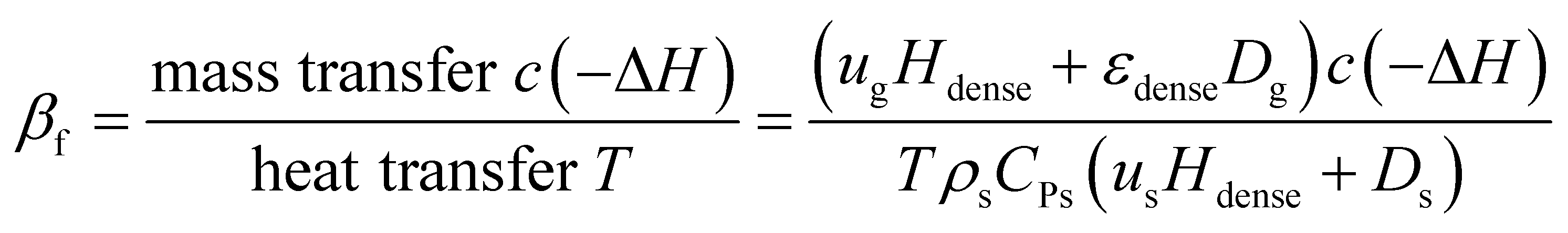 | (11) |
The fluidized Prater number βf is used to estimate temperature gradients in fluidized beds. When βf increases, the reaction heat rate increases faster than the heat transfer rate and the reaction heat couldn't be transferred efficiently, resulting in heat accumulation, large temperature gradient and even hot spots. When βf decreases, the heat transfer rate increases faster than the reaction heat rate and the reaction heat can be transferred efficiently, resulting in small temperature gradient. So like the Prater number β in fixed beds, the fluidized Prater number βf is a convenient criterion indicating large temperature gradient in fluidized beds. Fig. 2 shows the temperature gradient versus βf for the previously mentioned reaction units. With the increase of βf, the temperature gradient increases, validating the role of βf.
 | ||
| Fig. 2 Temperature gradient versus βf. | ||
Influence of gas velocity and bed diameter on the fluidized Prater number βf
For a specified reaction, except operating parameters, the most important parameters of βf is the dispersion coefficients of solids and gas. Fig. 3A and B, shows the dispersion coefficients of solids and gas versus gas velocity.1,39–50 The last three data points (20 kt, 50 kt, 100 kt) are derived from the investigated simulations and are close to Du's45 experimental results. So the simulated results are reliable in bubbling and turbulent regimes. Results from different researchers fluctuate within a certain range since their experimental conditions are not the same, especially the bed diameter. However, they all have similar trends with increase of gas velocity. For the solids dispersion coefficient, it increases with gas velocity at turbulent regime, and part of the resulting data even shows a non-linear increase45,48,50,51 While, with the further increase of gas velocity from turbulent regime to fast fluidization regime, the solids dispersion coefficient decreases suddenly to a very small value due to the phase separation and core-annular flow structure formed in the fast fluidization regime. For the gas dispersion coefficient, it increases with gas velocity at bubbling regime, then gradually decreases in the turbulent regime and finally decreases to a very small value in the fast fluidization regime. | ||
| Fig. 3 Solids and gas dispersion coefficients versus gas velocity and bed diameter. | ||
Fig. 3C and D show the solids and gas dispersion coefficients versus bed diameter. The solids and gas dispersion coefficients have an adverse relationship with the increase of bed diameter. For the solids dispersion coefficient, it increases with bed diameter which means a larger fluidized bed has a higher solids mixing ability and can be described by
| Ds = 0.2206D0.5 | (12) |
However, the gas dispersion coefficient decreases with bed diameter which means a larger fluidized bed has a lower gas mixing ability, and can be described by
| Dg = 0.0442D−0.4 | (13) |
Du's45 data of solids and gas dispersion coefficients at different gas velocities are used to calculate the βf to study the influence of gas velocity. The relationship of solids and gas dispersion coefficients at different bed diameters, eqn (12) and (13), are used to calculate βf to study the influence of bed diameter.
Fig. 4A shows the influence of gas velocity on βf. With the increase of gas velocity in the bubbling and turbulent regime, βf decreases gradually, which means the temperature gradient would decrease at the same time. But with the further increase of the gas velocity from the turbulent regime to the fast fluidization regime, βf jumps to a very large value, resulting in larger temperature gradient.
 | ||
| Fig. 4 Influence of gas velocity and bed diameter on βf. | ||
Thus, increasing gas velocity in the turbulent regime can decrease βf effectively and avoid the formation of hot spots in gas–solid fluidized beds. However, in practice, there lays an upper limit for the gas velocity, for the reason that βf goes up again into the fast fluidization regime. This significantly reduces the heat transfer rate and causes the temperature increase.
The above discussion brings one important issue for real operation of highly exothermic gas-solids fluidized bed reactors to light. When the reactor has a hot spot, decreased gas velocity may cause an increase in hot spot temperature in the fluidized bed, instead of the expected decrease with the decrease load of reaction capacity. The reason is due to the heat transfer ability decreasing more than the mass transfer, with the decreasing gas velocity. This is a dangerous operation zone, for both real case industrial operation and reactor control. Our simulation and experimental data both show this zone exists.
Fig. 4B shows the influence of the scale of the bed diameter on βf. With the increase of bed diameter, βf decreases, but the rate of decreasing slows down gradually. Which means an increased bed diameter in gas–solid fluidized beds can decrease the temperature gradient and avoid the generation of hot spot, especially at small and medium bed diameters.
The simulation results and the comparison with industrial data highlight a very important rule for a high exothermic reaction in a fluidized bed reactor scale up, there exists a diameter size for a fluidized bed, for both small and medium diameter, where there exists hot spot. When the reactor diameter increase to even larger, the hot spot disappears, due to the heat transfer ability increasing and the mass transfer ability decreasing. For the scale up of the fluidized bed reactor, checking for the hot spot is very important, and in many cases, scale down may also have a hot spot.
A series of simulations with different gas velocities and bed diameters were conducted in order to verify the rule. The axial temperature profiles at different gas velocities with a bed diameter of 2.6 m are shown in Fig. 5A. With a gas velocity increases from 0.3 m s−1 to 0.9 m s−1 and βf decreases from 1.13 to 0.86, the overall temperature decreases, the maximum temperature of the hot spots decreases and the axial temperature profiles tend to be more uniform. The axial temperature profiles of different bed diameters with a gas velocity of 0.7 m s−1 are shown in Fig. 5B. With a bed diameter increases from 0.3 m to 7 m and βf decreases from 0.94 to 0.75, the maximum temperature of the hot spots decreases and the axial temperature profiles tend to be more uniform as well.
 | ||
| Fig. 5 Axial temperature profile versus gas velocity and bed diameter. | ||
Operating map for industrial hydrogenation of nitrobenzene reaction
For the design and operation of a highly exothermic reaction in a fluidized bed reactor, an operation map for this type of system is important. Fig. 6 shows the operating map for the industrial hydrogenation of nitrobenzene reaction. Fig. 6A shows the temperature gradient versus the βf. The curve-fitting equation is
 | (14) |
 | ||
| Fig. 6 Operating map for hydrogenation of nitrobenzene reaction. | ||
This equation gives a convenient criterion for temperature gradient. According to the equation, when βf = 1, then ΔT/Tin = 0.152, which means when the inlet temperature is 200 °C, 473 K, then the temperature gradient is 72 °C. And if the temperature gradient must be controlled in 30 °C, then βf < 0.77.
Fig. 6B shows βf versus the Reynolds number, Re. The curve-fitting equation is
| βf = 5.73Re−0.14 | (15) |
The black points and the fitted curve are calculated from the mentioned simulations. The other three industrial data points are fitted well with the curve.14 Fig. 6 can be used to calculate the possible axial temperature gradient for the industrial hydrogenation of nitrobenzene reaction. This method and the fluidized Prater number βf can be promoted to other similar reactions.
Conclusions
In this investigation, a 2D pseudo homogeneous phase model was built to simulate the highly exothermic hydrogenation of nitrobenzene reaction in gas–solid fluidized reactors and then compared with the industrial temperature profiles. Simulation results and industrial data showed that for highly exothermic reactions, there could be hot spots even in fluidized beds, resulting in the deterioration of the catalyst, low conversion of the reactant, low yield of the desirable product and even security risks.Furthermore, the fluidized Prater number βf is introduced for theoretical analysis and the quantitative calculation of the temperature gradient. It is a criteria on comparing reaction heat production rate and heat transfer rate.
The cause of the hot spot and the effect of gas velocity and bed diameter have been analysed via βf. Contrary to fixed beds, in fluidized beds, with low gas velocity, there tends to be a large temperature gradient and hot spot. While with the increase of gas velocity in turbulent regime, βf decreases, the overall temperature decreases, the hot spot gradually disappears and the temperature profile tends to be more uniform. Therefore, the conventional idea to copy the operation from a fixed bed reactor to a fluidized bed reactor when the hot spot appears, which would be to decrease the gas velocity in order to decrease load, is incorrect and even dangerous. But the gas velocity cannot be too high into fast fluidization regime, in case that βf increases again and the temperature increases at the same time.
For the bed diameter, with small diameter, there tends to be a large temperature gradient and hot spot. While with the increase of bed diameter, βf decreases, the hot spot gradually disappears and the temperature profile tends to be more uniform. In addition, it is much easier to design a fluidized bed with large bed diameter to be operated in high gas velocity in turbulent regime, which is more effective to eliminate the hot spot problem.
An operating map for the industrial hydrogenation of nitrobenzene reaction is provided to estimate the possible axial temperature gradient by operating parameters, and this method can be utilized for other similar reactions.
Nomenclature
| a | Specific surface area of the heat exchanger, m−1 |
| c | Concentration of gas, mol m−3 |
| cC6H5NO2 | Concentration of C6H5NO2, mol m−3 |
| CPs | Specific heat of solids, J (kg−1 K−1) |
| DA | Effective diffusivity of reactant A in fixed beds, m2 s−1 |
| Ds | Solids dispersion coefficient, m2 s−1 |
| Dg | Gas dispersion coefficient, m2 s−1 |
| Hdense | Height of dense phase region, m |
| k | Chemical reaction rate coefficient, s−1 |
| keffective | Effective thermal conductivity of a porous catalyst in fixed beds, J (m−1 s−1 K−1) |
| ks | Thermal dispersion coefficient of solids, J (m−1 s−1 K−1) |
| Qc | Heat removal rate of cooling water, J (m−3 s−1) |
| Qp | Reaction heat production rate, J (m−3 s−1) |
| r | Chemical reaction rate, mol (m−3 s−1) |
| Re | The Reynolds number, dimensionless |
| T | Temperature, K |
| Tc | Temperature of cooling water, K |
| Tin | Temperature of inlet gas, K |
| us | Superficial velocity of solids, m s−1 |
| ug | Inlet velocity of gas, m s−1 |
| z | Axial height, m |
| αs | Heat transfer coefficient of heat exchanger, W (m−2 K−1) |
| β | The Prater number in fixed beds, dimensionless |
| βf | The fluidized Prater number, dimensionless |
| ρs | Apparent density of solids, kg m−3 |
| εdilute | Voidage in dilute phase region, dimensionless |
| εdense | Voidage in dense phase region, dimensionless |
| ΔH | Heat of chemical reaction, J mol−1 |
| ΔT | Temperature gradient, K |
Acknowledgements
This work was supported by the National Basic Research Program of China (973 Program, 2011CB932602), the National Natural Science Foundation of China (No.20141301065 and 21306103) and Tsinghua National Laboratory for Information Science and Technology.Notes and references
- H. T. Bi, N. Ellis, I. A. Abba and J. R. Grace, Ind. Eng. Chem. Fundam., 2000, 55, 4789 CAS.
- J. R. Grace, Powder Technol., 2000, 113, 242 CrossRef CAS.
- A. Stefanova, H. T. Bi, C. J. Lim and J. R. Grace, Int. J. Heat Mass Transfer, 2008, 51, 2020 CrossRef CAS.
- J. Wang, Particuology, 2010, 8, 176 CrossRef.
- A. Stefanova, Heat Transfer Near The Transition to Turbulent Fluidization, The University of British Columbia, 2009 Search PubMed.
- V. V. Ranade, Computational Flow Modeling For Chemical Reactor Engineering, 2002 Search PubMed.
- M. Rüdisüli, T. J. Schildhauer, S. M. A. Biollaz and J. R. van Ommen, Powder Technol., 2012, 217, 21 CrossRef.
- S. Ge, L. Xinchun, Q. Weizhong, C. Wei, S. Congyu, S. Yongjun and Y. Xiaoqiu, Energy Procedia, 2012, 29, 552 CrossRef.
- J. Werther and E.-U. Hartge, Ind. Eng. Chem. Res., 2004, 43, 5593 CrossRef CAS.
- S. Khajeh, Z. Arab Aboosadi and B. Honarvar, J. Nat. Gas Sci. Eng., 2014, 19, 152 CrossRef CAS.
- M. R. Rahimpour and M. Bayat, Int. J. Hydrogen Energy, 2011, 36, 6616 CrossRef CAS.
- K. V. N. S. Rao and G. V. Reddy, Combust. Sci. Technol., 2007, 179, 1589 CrossRef CAS.
- Z. Li, M. van Sint Annaland, J. A. M. Kuipers and N. G. Deen, Chem. Eng. Sci., 2016, 140, 279 CrossRef CAS.
- W.-z. Qian, C.-h. Ke, X.-m. Fang and G. X. Fei Wei, Mod. Chem. Ind., 2005, 25, 49–53 CAS.
- J. C. Song, N. Yutani and L. T. Fan, Ind. Eng. Chem. Fundam., 1984, 23, 170–174 CAS.
- E. Pourazadi, R. Vakili, D. Iranshahi, A. Jahanmiri and M. R. Rahimpour, Can. J. Chem. Eng., 2013, 91, 54 CrossRef CAS.
- Y. Kaneko, T. Shiojima and M. Horio, Chem. Eng. Sci., 1999, 54(24), 5809–5821 CrossRef CAS.
- W. Xiaobo, Study of Muti-Stage Fluidized bed Reactor for Producing Vinyl Chloride from Acetylene and Non-mercury Catalyst, Tsinghua University, 2008 Search PubMed.
- S. Artlich, E.-U. Hartge and J. Werther, Ind. Eng. Chem. Res., 1998, 37, 782 CrossRef CAS.
- P. B. Weisz and J. S. Hicks, Chem. Eng. Sci., 1962, 17, 265 CrossRef CAS.
- L. A. Belfiore, Can. J. Chem. Eng., 2007, 85, 268 CrossRef CAS.
- Y. Behjat, S. Shahhosseini and S. H. Hashemabadi, Int. Commun. Heat Mass Transfer, 2008, 35, 357 CrossRef.
- H. Yiannoulakis, A. Yiagopoulos and C. Kiparissides, Chem. Eng. Sci., 2001, 56, 917 CrossRef CAS.
- S. A. Scott, J. F. Davidson, J. S. Dennis and A. N. Hayhurst, Ind. Eng. Chem. Res., 2004, 43, 5632 CrossRef CAS.
- Z. Y. Zhou, A. B. Yu and P. Zulli, AIChE J., 2009, 55, 868 CrossRef CAS.
- J. M. Matsen, Powder Technol., 1996, 88, 237 CrossRef CAS.
- Y. Che, Z. Tian, Z. Liu, R. Zhang, Y. Gao, E. Zou, S. Wang and B. Liu, Powder Technol., 2015, 286, 107 CrossRef CAS.
- Y.-Q. Zhuang, X.-M. Chen, Z.-H. Luo and J. Xiao, Comput. Chem. Eng., 2014, 60, 1 CrossRef CAS.
- H. Liu, R. J. Cattolica and R. Seiser, Int. J. Hydrogen Energy, 2016, 41, 11974 CrossRef CAS.
- H. Pan, X.-Z. Chen, X.-F. Liang, L.-T. Zhu and Z.-H. Luo, Powder Technol., 2016, 299, 235 CrossRef CAS.
- Y. Che, Z. Tian, Z. Liu, R. Zhang, Y. Gao, E. Zou, S. Wang and B. Liu, Powder Technol., 2015, 278, 94 CrossRef CAS.
- S. Schneiderbauer, S. Puttinger, S. Pirker, P. Aguayo and V. Kanellopoulos, Chem. Eng. J., 2015, 264, 99 CrossRef CAS.
- L.-T. Zhu, L. Xie, J. Xiao and Z.-H. Luo, Chem. Eng. Sci., 2016, 143, 369 CrossRef CAS.
- Z. Wang, Gas mixing and hydrodynamic behaviors in a turbulent fluidized bed, Tsinghua University, 1997 Search PubMed.
- M. Jinsheng, Chem. React. Eng. Technol., 1988, 4, 64 Search PubMed.
- W. Zhi-guo, J. Shan and W. Fei, Chem. React. Eng. Technol., 2001, 17, 278–281 Search PubMed.
- M. S. Murthy, Chem. Age India, 1963, 14, 653 CAS.
- M. Das, A. Bandyopadhyay, B. C. Meikap and R. K. Saha, Chem. Eng. J., 2008, 145, 249 CrossRef CAS.
- M. Foka, J. Chaouki, C. Guy and D. Klvana, Chem. Eng. Sci., 1996, 51, 713 CrossRef CAS.
- J. Liu, J. R. Grace, H. T. Bi, H. Morikawa and J. Zhu, Chem. Eng. Sci., 1999, 54(22), 5441–5449 CrossRef CAS.
- H. I. Cho, C.-H. Chung, G. Y. Han, G. R. Ahn and J. S. Kong, Korean J. Chem. Eng., 2000, 17(3), 292 CrossRef CAS.
- J. Sterneus, F. Johnsson and B. Leckner, Powder Technol., 2002, 126, 28 CrossRef CAS.
- Y. Yanhui, J. Xinli, W. Fei and J. Yong, Chin. J. Chem. Eng., 2001, 9, 291 Search PubMed.
- R. Krishna and J. M. v. Baten, Chem. Eng. J., 2001, 82, 247 CrossRef CAS.
- B. Du, L.-S. Fan, F. Wei and W. Warsito, AIChE J., 2002, 48, 1896 CrossRef CAS.
- R. W. Breault, Powder Technol., 2006, 163, 9 CrossRef CAS.
- V. Jiradilok, D. Gidaspow and R. W. Breault, Chem. Eng. Sci., 2007, 62, 3397 CrossRef CAS.
- Y. Zhang, C. Lu and M. Shi, Chem. Eng. Res. Des., 2009, 87, 1400 CrossRef CAS.
- B. Chalermsinsuwan, D. Gidaspow and P. Piumsomboon, Chem. Eng. J., 2011, 171, 301 CrossRef CAS.
- A. Avidan and J. Yerushalmi, AIChE J., 1985, 31, 835 CrossRef CAS.
- D. Gidaspow, J. Jung and R. K. Singh, Powder Technol., 2004, 148, 123 CrossRef CAS.
| This journal is © The Royal Society of Chemistry 2017 |