
 Open Access Article
 This Open Access Article is licensed under a Creative Commons Attribution-Non Commercial 3.0 Unported Licence
Enhancement of nitrogen and sulfur co-doping on the electrocatalytic properties of carbon nanotubes for VO2+/VO2+ redox reaction
Chuanchang Li *ab,
Baoshan Xieab,
Jian Chenab,
Jianjun Heab and
Zhangxing He*c
*ab,
Baoshan Xieab,
Jian Chenab,
Jianjun Heab and
Zhangxing He*c
aKey Laboratory of Efficient & Clean Energy Utilization, The Education Department of Hunan Province, Changsha University of Science and Technology, Changsha 410114, China. E-mail: chuanchangli@csust.edu.cn; Fax: +86-0731-85258409; Tel: +86-0731-85258409
bSchool of Energy and Power Engineering, Changsha University of Science and Technology, Changsha 410114, China
cSchool of Chemical Engineering, North China University of Science and Technology, Tangshan 063009, China. E-mail: zxhe@ncst.edu.cn; Fax: +86-0315-2592574; Tel: +86-0315-2592574
First published on 24th February 2017
Abstract
Heteroatom doping on the surface of an electrode and catalyst can impact the surface and electronic properties. Herein, nitrogen and sulfur co-doped multi-walled carbon nanotubes (denoted as MWCNTs-NS) prepared via a pyrolysis method, in which thiourea served as both nitrogen and sulfur sources, were investigated as an electrocatalyst for the VO2+/VO2+ redox couple in vanadium redox flow battery. It was revealed that the pyrolysis process had no effect on the microstructure of MWCNTs. The VO2+/VO2+ redox reaction on MWCNTs-NS exhibited higher electrochemical kinetics when compared with that on pristine and nitrogen-doped MWCNTs. The nitrogen and sulfur co-doping for MWCNTs can decrease the charge transfer resistance of the VO2+/VO2+ redox reaction. Static cells using graphite felt modified by the MWCNTs samples were employed to evaluate their electrocatalytic properties for the VO2+/VO2+ reaction. The cell using the MWCNTs-NS electrocatalyst showed the smallest electrochemical polarization, resulting in a larger energy density and energy efficiency. The results indicate that MWCNTs-NS is a novel efficient catalyst for the VO2+/VO2+ redox reaction with excellent electrocatalytic properties.
1. Introduction
Vanadium redox flow battery (VRFB), as a promising large-scale energy storage system, has attracted significant attention of researchers due to its long life and high energy efficiency.1,2 The electrolyte, electrode, and membrane are the three main components for the VRFB. The sluggishness of redox reactions on the electrode in the membrane separated side partly limits the development of the VRFB. The VO2+/VO2+ redox reaction is particularly sluggish when compared with the V2+/V3+ redox reaction.3 Therefore, catalyst materials with high electrocatalytic properties are required to improve the electrochemical activity of the VO2+/VO2+ redox couple.4,5Carbonaceous materials doped by heteroatoms, such as N, B, and O, exhibit especial electrochemical and physical properties, attracting significant attention of the researchers in the past few decades.6–10 Chemical doping has been acknowledged as a superior approach to break the sluggishness of the carbon layer and to change the chemical electronic properties by modulating the electron states.11 Substitutional doping with heteroatoms into the carbon framework can modulate the chemical properties and create new active sites, further improving the electrocatalytic activity of carbonaceous materials.12–14 Furthermore, co-doping by multi-elements with different electronegativities can result in a unique electron distribution, causing a positive synergistic effect.15 Liu et al.16 reported that B and N co-doped carbon nanofibers exhibit an outstanding electrochemical activity for the VO2+/VO2+ redox couple, which is better than N or B mono-doped carbon nanofibers. The electrocatalytic properties towards the VO2+/VO2+ redox couple are mainly determined by the type of incorporation of B and N into the carbon nanostructure. Flox et al.17 modified PAN-based graphite felt by a thermochemical treatment using an NH3/O2 mixed gas. The nitrogen and oxygen-containing groups were incorporated onto the graphite felt surface, with the nitrogen and oxygen contents of up to 8% and 32%, respectively. The introduced groups could facilitate electron transfer through the electrolyte/electrode interface both for the oxidation and reduction processes.
Carbon nanotubes have been widely applied in electrochemical fields such as lithium-ion batteries, fuel cells, electroanalytical chemistry, and flow batteries due to their unique chemical and physical performance.18–21 Carbon nanotubes have been acknowledged as a superior electrocatalyst or support for redox couples in VRFBs.22–24 For instance, Li et al.25 compared the electrocatalytic activity of functionalized multi-walled carbon nanotube for the VO2+/VO2+ couple and found that the VO2+/VO2+ reaction exhibited the highest electrocatalytic kinetics on carboxyl MWCNTs compared with that on pristine and hydroxyl MWCNTs. He et al.26 developed a Mn3O4/MWCNTs composite catalyst via a solvothermal method, and the composite revealed superior electrocatalytic properties for the VO2+/VO2+ redox couple due to the synergistic effect of Mn3O4 and MWCNTs. Han et al.27 prepared a graphene oxide nanosheets/MWCNTs hybrid using an electrostatic spray technique. This hybrid demonstrated superior electrocatalytic performance towards the VO2+/VO2+ couple in VRFB, resulting from the formation of an effective mixed conducting network.
In this study, N and S co-doped carbon nanotubes were prepared for the first time, which were employed as electrocatalytic materials for the VO2+/VO2+ redox couple, and their electrochemical kinetics and battery performance were investigated for VRFB.
2. Experimental
2.1. Preparation
MWCNTs and thiourea were added to 30 mL ethanol and then stirred for 30 min. The suspension was heated under agitation at 50 °C to evaporate ethanol. The molar ratio of MWCNTs to thiourea was set at 4![[thin space (1/6-em)]](https://www.rsc.org/images/entities/char_2009.gif) :1. The resulting solid was sintered at 800 °C for 2 h under an Ar atmosphere with the gas flowing for 2 h before heating to eliminate the air. The product was denoted as MWCNTs-NS. For comparison, pristine and N-doped MWCNTs were prepared in the absence of thiourea and by replacing thiourea with urea in the same molar ratio. The samples were then denoted as MWCNTs and MWCNTs-N, respectively.
:1. The resulting solid was sintered at 800 °C for 2 h under an Ar atmosphere with the gas flowing for 2 h before heating to eliminate the air. The product was denoted as MWCNTs-NS. For comparison, pristine and N-doped MWCNTs were prepared in the absence of thiourea and by replacing thiourea with urea in the same molar ratio. The samples were then denoted as MWCNTs and MWCNTs-N, respectively.
2.2. Characterization
The microstructure of the samples was studied using a Nova NanoSEM230 FE-SEM at a 10 kV accelerating voltage, and a JEOL JEM-2100F TEM with a LaB6 filament as the electron source. X-ray photoelectron spectroscopy (XPS) measurements were performed via a K-Alpha 1063 (Thermo Fisher Scientific) using Al Kα radiation (6 mA, 12 kV).2.3. Electrochemical measurements
Cyclic voltammetry measurements were performed using a CHI660E electrochemical workstation (Shanghai Chenhua Instrument, China) via the three-electrode system. The three-electrode system included a glassy carbon electrode covered by the MWCNTs sample as the working electrode, a saturated calomel electrode as the reference electrode, and a Pt electrode as the counter electrode. The measurements were performed at the scan rate of 20 mV s−1 in the range of 0.2–1.6 V in a 3.0 mol L−1 H2SO4 + 2.0 mol L−1 VOSO4 electrolyte solution. The glassy carbon electrodes modified by the MWCNTs samples were prepared as follows. The glassy carbon electrode was polished as described in the literature.25 Then, 10 mg MWCNTs sample was dispersed in 5 mL dimethylformamide by ultrasonication for 2 h. A 20 μL of the suspension was placed on the glassy carbon electrode. The glassy carbon electrode with the suspension was heated at 80 °C for 8 h in an oven.Electrochemical impedance spectroscopy measurements were conducted using a 3.0 mol L−1 H2SO4 + 1.0 mol L−1 VOSO4 solution with an amplitude of 5 mV in the frequency range of 10−1 to 105 Hz at the ambient temperature. The measured system and electrochemical workstation used were the same as those for the cyclic voltammetry measurements.
2.4. Charge–discharge test
The charge–discharge performance of the cell was evaluated via a single static cell. The cell was assembled by two pieces of 3 × 3 cm2 polyacrylonitrile-based graphite felt (6 mm, Shenhe Carbon Fiber Materials Co. Ltd., China) as the electrode, a perfluorinated ion-exchange membrane (Nepem-1110, Best Industrial & Trade Co., Ltd., China), and conductive plastics (1.0 mm, Guangdong Foshan Plastics Factory) as the current collector; 1.6 mol L−1 V3+/V4+ (molar ratio: 1:1) were the original electrolytes in both the negative and positive sides. The tests were conducted in the range of 0.7–1.7 V at the current density of 50 mA cm−2 for 50 cycles using a battery test system (CT2001C-10 V/5 A, Wuhan Land Co., China). The graphite felts modified by the MWCNTs samples were prepared as follows. Graphite felts were washed with distilled water via ultrasonication and then dried at 100 °C for 10 h. The graphite felts were then immersed in MWCNTs-dispersed dimethylformamide with the concentration of 0.4 mg mL−1 and then dried at 100 °C for 24 h.
3. Results and discussion
3.1. SEM and TEM
The SEM images of MWCNTs, MWCNTs-N, and MWCNTs-NS are shown in Fig. 1a–c. As observed, the doping of heteroatoms has no obvious influence on the morphologies of MWCNTs. The TEM image of MWCNTs-NS (see Fig. 1d) confirms the type of multi-walled carbon nanotube, and MWCNTs have an average diameter of about 25 nm with a thickness of about 8 nm. | ||
| Fig. 1 SEM images of MWCNTs (a), MWCNTs-N (b), MWCNTs-NS (c), and TEM image of MWCNTs-NS (d). | ||
3.2. XPS
The incorporation of heteroatoms (N and S) was confirmed by the XPS measurements. The XPS full scan spectrum of MWCNTs-NS is shown in Fig. 2a. Correspondingly, the atomic percentage of MWCNTs-NS was evaluated as 96.69% for C, 0.86% for S, 1.23% for N, and 1.22% for O. The peak fitting of S2p and N1s for MWCNTs-NS is presented in Fig. 2b and c. The high-resolution S2p peak at about 164 eV is deconvoluted into three constituent peaks. The major peaks situated at the binding energies of 162.7 eV and 163.8 eV can be ascribed to C–S bonding arising from spin–orbit coupling.28,29 The minor peak at the binding energy of 167.8 eV is attributed to the oxidized sulfur moieties (–SOn–).12 The high-resolution N1s spectrum of MWCNTs-NS demonstrates the existence of pyrrole-like N (400.6 eV) and pyridine-like N (398.5 eV) species (see Fig. 2c), which can be employed as dopants, resulting in the formation of defects on the surface of the graphite felt.30–32 The presence of O atoms may originate from the physicochemically adsorbed oxygen on the surface of MWCNTs.33 The XPS results indicate that N and S heteroatoms are incorporated into the carbon framework of MWCNTs via this method, further serving as active sites.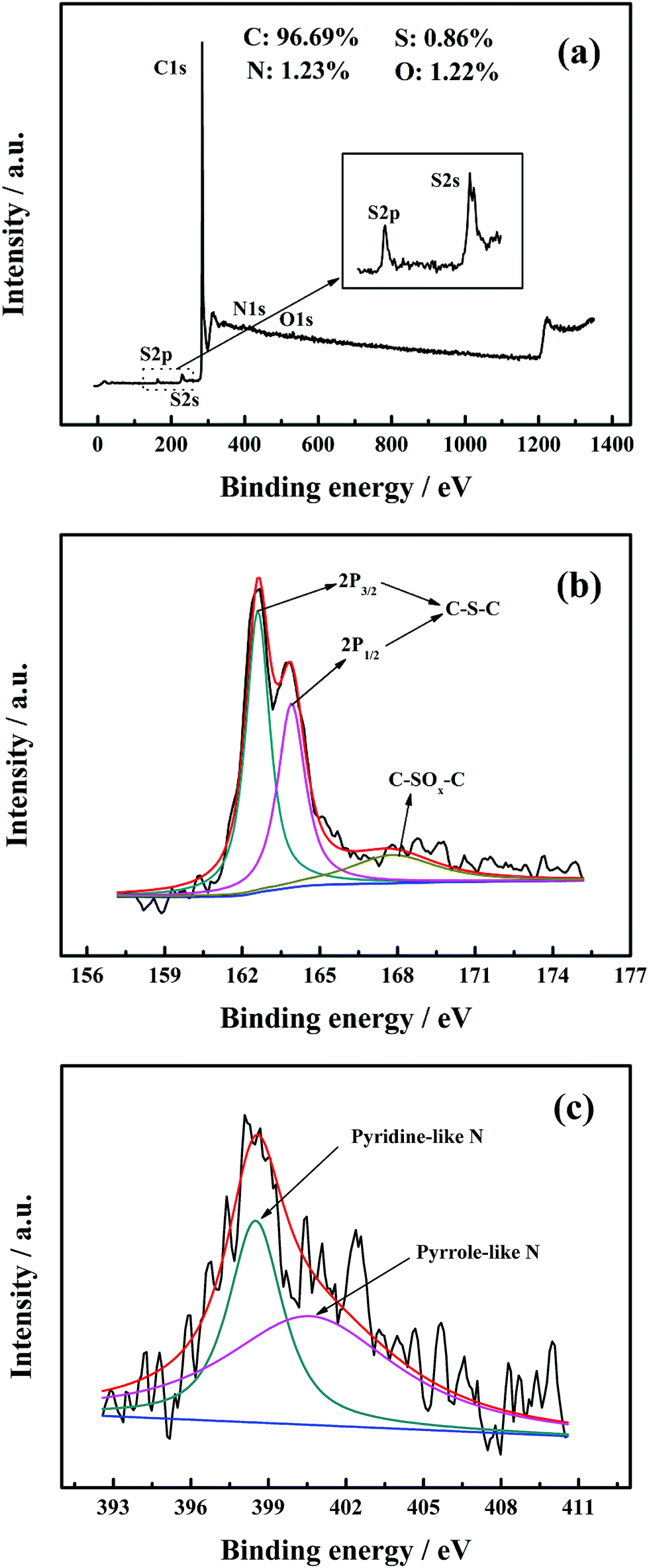 | ||
| Fig. 2 XPS survey of MWCNTs-NS (a) and high resolution XPS of S2p (b) and N1s (c). | ||
3.3. Cyclic voltammetry
The cyclic voltammetry curves of the glass carbon electrodes modified by the MWCNTs samples are shown in Fig. 3, and the corresponding electrochemical parameters are presented in Table 1. The cathodic and anodic peak shapes corresponding to the reduction and oxidation processes for the VO2+/VO2+ reaction are obvious for all the MWCNTs samples. The cathodic and anodic peaks are situated at approximately 0.8 V and 1.1 V, respectively. As for the three MWCNTs samples, the peak currents are in the order of MWCNTs-NS > MWCNTs-N > MWCNTs for both the reduction and oxidation processes. The anodic peak currents for the MWCNTs-NS and MWCNTs-N are 1.13 mA and 0.51 mA larger than that for the pristine MWCNTs, and the corresponding cathodic peak currents are 0.85 mA and 0.31 mA larger than that for the pristine MWCNTs, respectively. It suggests that the electrochemical activity of the VO2+/VO2+ couple on the modified MWCNTs is higher than that on the pristine MWCNTs, especially for MWCNTs-NS. The peak potential intervals (ΔEp) of MWCNTs-NS and MWCNTs-N are 251 mV and 276 mV, respectively, which are both smaller than that of the pristine MWCNTs (417 mV). Moreover, the ratios of the cathodic peak current to anodic peak current (Ipc/Ipa) of the modified MWCNTs are closer to 1 compared to that of the pristine MWCNTs. Note that the value of Ipc/Ipa is in the range of 0.4–0.6, which is probably due to a portion of VO2+ ions diffusing into the bulk measured solution of VO2+ ions after the oxidation of VO2+ ions, resulting in smaller cathodic peak current compared with the anodic peak current. Smaller ΔEp and better symmetry of the peak shape indicate that the VO2+/VO2+ redox couple exhibits best electrochemical reversibility on MWCNTs-NS. The results demonstrate that the electrochemical kinetics of the VO2+/VO2+ redox couple on MWCNTs can be improved by the incorporation of heteroatoms, and the electrocatalytic kinetics of the redox reaction were in the order of MWCNTs-NS > MWCNTs-N > MWCNTs.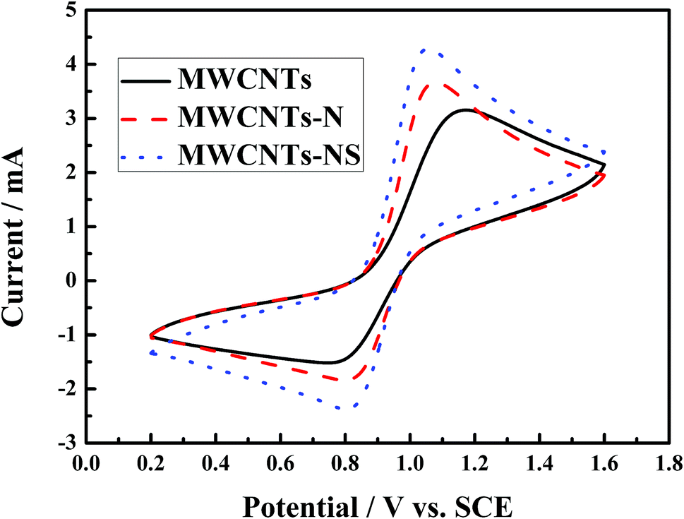 | ||
| Fig. 3 Cyclic voltammetry curves of glass carbon electrodes modified by different MWCNTs samples at the scan rate of 20 mV s−1 in a 2.0 mol L−1 VOSO4 + 3.0 mol L−1 H2SO4 electrolyte solution. | ||
| Sample | Ipa (mA) | Ipc (mA) | ΔEp (mV) | Ipc/Ipa |
|---|---|---|---|---|
| a Ipa: anodic peak, Ipc: cathodic peak, ΔEp: peak potential interval. | ||||
| MWCNTs | 3.152 | 1.520 | 417 | 0.482 |
| MWCNTs-N | 3.664 | 1.839 | 276 | 0.502 |
| MWCNTs-NS | 4.286 | 2.376 | 251 | 0.554 |
The excellent electrocatalytic properties of MWCNTs-NS for the VO2+/VO2+ redox reaction can be explained as follows. First, compared with doping by one heteroatom, co-doping by two heteroatoms can lead to an increase in the number of heteroatoms, resulting in the increase of active sites.30,34 Second, the unique structural features and synergistic effect of the N and S co-doping, due to the redistribution of spin and charge density and newly created active sites, can improve the electrocatalytic properties of MWCNTs.11,35–37
3.4. Electrochemical impedance spectroscopy
The electrochemical impedance spectroscopy of the MWCNTs samples in a 1.0 mol L−1 VOSO4 + 3.0 mol L−1 H2SO4 solution at the open-circuit voltage are presented in Fig. 4. Z′ with the value of about 11 Ω at Z′′ = 0 is the ohmic resistance, which includes electrode, electrolyte, and electrode/electrolyte surface contact resistance.16 The ohmic resistance remains almost constant for the three MWCNTs samples due to its nature of high conductivity. The semicircle at high frequency in Nyquist plots corresponds to the charge transfer process between the electrolyte and electrode surface, and the radius of the semicircle reflects the value of the charge transfer resistance.38,39 As can be seen from Fig. 4, the charge transfer resistance of the VO2+/VO2+ couple is in the order of MWCNTs-NS > MWCNTs-N > MWCNTs. The results are in agreement with the results of the cyclic voltammetry measurements. The electrochemical impedance spectroscopy and cyclic voltammetry results demonstrate that the incorporation of heteroatoms for MWCNTs enhances the electrochemical kinetics of the VO2+/VO2+ couple, especially for MWCNTs-NS.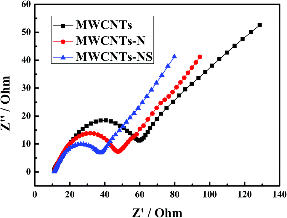 | ||
| Fig. 4 Electrochemical impedance spectroscopy of glassy carbon electrodes modified by different MWCNTs samples in 1.0 mol L−1 VOSO4 + 3.0 mol L−1 H2SO4 at open-circuit voltage. | ||
3.5. Charge–discharge test
SEM images of the pristine graphite felt and MWCNTS-NS-modified graphite felt are compared in Fig. 5. The graphite felt has a diameter of about 13 μm. As observed, the MWCNTs-NS sample can be attached to the surface of the graphite felt via ultrasonication. The introduction of MWCNTs with a large surface area can provide more electrode reaction places for the redox couple. Moreover, the introduced N and S heteroatoms on MWCNTs-NS can be employed as active sites. The increase in the reaction places and introduced active sites are beneficial for the electrochemical performance of the vanadium redox flow battery.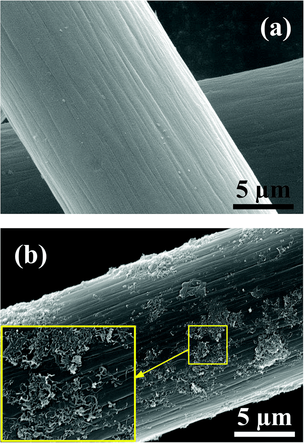 | ||
| Fig. 5 SEM images of the pristine graphite felt (a) and MWCNTs-NS modified graphite felt (b). | ||
The 10th charge–discharge curves of the cells using the MWCNTs samples as a catalyst in the positive side at the current density of 50 mA cm−2 are shown in Fig. 6. As can be seen, the cells using MWCNTs and MWCNTs-NS exhibit larger charge–discharge times, lower charge voltages, and higher discharge voltages. A longer charge–discharge time would lead to an increase of discharge capacity of the cell, and a higher discharge voltage would increase the energy density of the VRFB system. As for the two cells using MWCNTs and MWCNTs-NS as catalysts for the VO2+/VO2+ redox couple, the cell using MWCNTs-NS exhibits better electrochemical properties compared with the pristine cell.
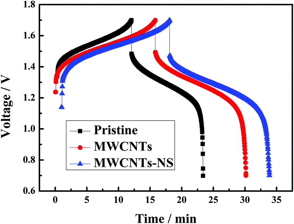 | ||
| Fig. 6 The 10th charge–discharge curves of the cell using the MWCNTs samples as a catalyst in the positive side at a current density of 50 mA cm−2. | ||
The discharge capacity and efficiency of the cells using different MWCNTs samples at the current density of 50 mA cm−2 are shown in Fig. 7. As can be seen, the discharge capacity significantly increases when employing the MWCNTs samples as a catalyst in the positive side. The initial discharge capacity of the cells using MWCNTs and MWCNTs-NS are 120.1 mA h and 128.5 mA h, respectively, which are much larger than that without a catalyst (97.0 mA h). As for the two MWCNTs samples, the cell using a MWCNTs-NS catalyst exhibits a larger discharge capacity. The retentions of the discharge capacity for 40 cycles using MWCNTs and MWCNTs-NS are 75.3% and 76.5%, respectively, which are comparable with that of the pristine cell (70.4%), indicating the high stability of the electrochemical activity of the MWCNTs samples. The average coulombic efficiencies of the cells using MWCNTs and MWCNTs-NS for 40 cycles are 97.6% and 96.1%, slightly lower than that of the pristine cell (98.1%). This is ascribed to the slightly severe self-discharge originating from the longer charge–discharge process. However, the energy efficiency of the cells increased by 3.5% and 5.1% when using MWCNTs and MWCNTs-NS catalysts, respectively, compared with that of the pristine cell (73.8%). The large discharge capacity and efficiency demonstrate the improvement of the electrochemical performance of the cell by MWCNTs samples, especially for MWCNTs-NS.
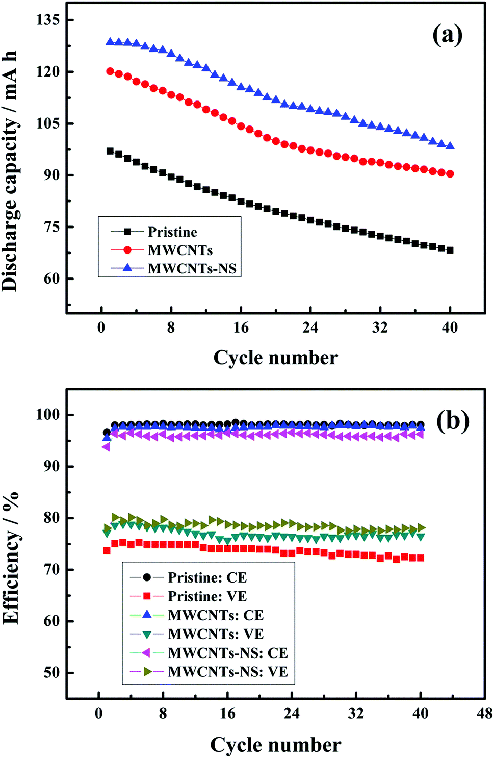 | ||
| Fig. 7 The discharge capacity (a) and efficiency (b) of the cells using different MWCNTs samples as a function of cycle number at the current density of 50 mA cm−2. | ||
4. Conclusion
We reported nitrogen and sulfur co-doped carbon nanotubes (MWCNTs-NS) synthesized via a simple route of direct carbonization using thiourea. The MWCNTs-NS exhibit excellent electrocatalytic properties for the VO2+/VO2+ redox couple in the VRFB. The heteroatom doping process has no effect on the surface morphologies of MWCNTs. The cell using the MWCNTs-NS electrocatalyst reveals an improvement in the discharge capacity and energy efficiency. MWCNTs-NS is a novel catalyst for the VO2+/VO2+ redox reaction with excellent electrocatalytic properties, further improving the comprehensive energy storage performance for the VRFB system.Acknowledgements
This work was supported by the National Natural Science Foundation of China (51504041), the Natural Science Foundation of Hunan Province (2016JJ3009), the Scientific Research Fund of Hunan Provincial Education Department (15K007), and the Key Laboratory of Efficient & Clean Energy Utilization, The Education Department of Hunan Province (2015NGQ008).Notes and references
- Z. He, L. Liu, C. Gao, Z. Zhou, X. Liang, Y. Lei, Z. He and S. Liu, RSC Adv., 2013, 3, 19774–19777 RSC.
- Y.-C. Chang, Y.-C. Shih, J.-Y. Chen, G.-Y. Lin, N.-Y. Hsu, Y.-S. Chou and C.-H. Wang, RSC Adv., 2016, 6, 102068–102075 RSC.
- A. Ejigu, M. Edwards and D. A. Walsh, ACS Catal., 2012, 5, 7122–7130 CrossRef.
- Y. Huang, J. Huo, S. Dou, K. Hu and S. Wang, RSC Adv., 2016, 6, 66368–66372 RSC.
- H. T. Thu Pham, C. Jo, J. Lee and Y. Kwon, RSC Adv., 2016, 6, 17574–17582 RSC.
- A. M. Pezeshki, J. T. Clement, G. M. Veith, T. A. Zawodzinski and M. M. Mench, J. Power Sources, 2015, 294, 333–338 CrossRef CAS.
- K. Parvez, S. Yang, Y. Hernandez, A. Winter, A. Turchanin, X. Feng and K. Müllen, ACS Nano, 2012, 6, 9541–9550 CrossRef CAS PubMed.
- Z.-S. Wu, A. Winter, L. Chen, Y. Sun, A. Turchanin, X. Feng and K. Muellen, Adv. Mater., 2012, 24, 5130–5135 CrossRef CAS PubMed.
- S. Yang, L. Zhi, K. Tang, X. Feng, J. Maier and K. Muellen, Adv. Funct. Mater., 2012, 22, 3634–3640 CrossRef CAS.
- L. Yang, S. Jiang, Y. Zhao, L. Zhu, S. Chen, X. Wang, Q. Wu, J. Ma, Y. Ma and Z. Hu, Angew. Chem., Int. Ed., 2011, 50, 7132–7135 CrossRef CAS PubMed.
- X. Duan, K. O'Donnell, H. Sun, Y. Wang and S. Wang, Small, 2015, 11, 3036–3044 CrossRef CAS PubMed.
- Z. Yang, Z. Yao, G. Li, G. Fang, H. Nie, Z. Liu, X. Zhou, X. A. Chen and S. Huang, ACS Nano, 2012, 6, 205–211 CrossRef CAS PubMed.
- J. Jin, X. Fu, Q. Liu, Y. Liu, Z. Wei, K. Niu and J. Zhang, ACS Nano, 2013, 7, 4764–4773 CrossRef CAS PubMed.
- H. Wang, T. Maiyalagan and X. Wang, ACS Catal., 2012, 2, 781–794 CrossRef CAS.
- X.-K. Kong, C.-L. Chen and Q.-W. Chen, Chem. Soc. Rev., 2014, 43, 2841–2857 RSC.
- L. Shi, S. Liu, Z. He, H. Yuan and J. Shen, Electrochim. Acta, 2015, 178, 748–757 CrossRef CAS.
- C. Flox, J. Rubio-García, M. Skoumal, T. Andreu and J. R. Morante, Carbon, 2013, 60, 280–288 CrossRef CAS.
- Q. S. Song, G. K. Aravindaraj, H. Sultana and S. L. I. Chan, Electrochim. Acta, 2007, 53, 1890–1896 CrossRef CAS.
- H. Trotter, R. Phillips, B. Ni, Y. H. Hu, S. B. Sinnott, P. T. Mikulski and J. A. Harrison, J. Nanosci. Nanotechnol., 2005, 5, 536–541 CrossRef CAS PubMed.
- C.-Z. Li, Z.-B. Wang, X.-L. Sui, L.-M. Zhang and D.-M. Gu, RSC Adv., 2016, 6, 32290–32297 RSC.
- Z. Yang, X. Yu, Y. Zhang and G. Xu, RSC Adv., 2016, 6, 108158–108163 RSC.
- S. Yang, H. Song, X. Chen, A. V. Okotrub and L. G. Bulusheva, Electrochim. Acta, 2007, 52, 5286–5293 CrossRef CAS.
- D. T. Welna, L. Qu, B. E. Taylor, L. Dai and M. F. Durstock, J. Power Sources, 2011, 196, 1455–1460 CrossRef CAS.
- W. Li, J. Liu and C. Yan, Electrochim. Acta, 2012, 79, 102–108 CrossRef CAS.
- W. Li, J. Liu and C. Yan, Carbon, 2011, 49, 3463–3470 CrossRef CAS.
- Z. He, L. Dai, S. Liu, L. Wang and C. Li, Electrochim. Acta, 2015, 176, 1434–1440 CrossRef CAS.
- P. X. Han, Y. H. Yue, Z. H. Liu, W. Xu, L. X. Zhang, H. X. Xu, S. M. Dong and G. L. Cui, Energy Environ. Sci., 2011, 4, 4710–4717 CAS.
- X. Yu and H. S. Park, Carbon, 2014, 77, 59–65 CrossRef CAS.
- X. Yu, Y. Kang and H. S. Park, Carbon, 2016, 101, 49–56 CrossRef CAS.
- W. Ai, Z. M. Luo, J. Jiang, J. H. Zhu, Z. Z. Du, Z. X. Fan, L. H. Xie, H. Zhang, W. Huang and T. Yu, Adv. Mater., 2014, 26, 6186–6192 CrossRef CAS PubMed.
- Z. He, L. Shi, J. Shen, Z. He and S. Liu, Int. J. Energy Res., 2015, 39, 709–716 CrossRef CAS.
- W. Ai, W. Zhou, Z. Du, Y. Du, H. Zhang, X. Jia, L. Xie, M. Yi, T. Yu and W. Huang, J. Mater. Chem., 2012, 22, 23439–23446 RSC.
- J. Wu, Z. R. Yang, X. W. Li, Q. J. Sun, C. Jin, P. Strasser and R. Z. Yang, J. Mater. Chem. A, 2013, 1, 9889–9896 CAS.
- J. P. Paraknowitsch and A. Thomas, Energy Environ. Sci., 2013, 6, 2839–2855 CAS.
- S.-A. Wohlgemuth, R. J. White, M.-G. Willinger, M.-M. Titirici and M. Antonietti, Green Chem., 2012, 14, 1515–1523 RSC.
- J. Xu, G. Dong, C. Jin, M. Huang and L. Guan, ChemSusChem, 2013, 6, 493–499 CrossRef CAS PubMed.
- J. Liang, Y. Jiao, M. Jaroniec and S. Z. Qiao, Angew. Chem., Int. Ed., 2012, 51, 11496–11500 CrossRef CAS PubMed.
- Y. Shao, X. Wang, M. Engelhard, C. Wang, S. Dai, J. Liu, Z. Yang and Y. Lin, J. Power Sources, 2010, 195, 4375–4379 CrossRef CAS.
- W. H. Wang and X. D. Wang, Electrochim. Acta, 2007, 52, 6755–6762 CrossRef CAS.
| This journal is © The Royal Society of Chemistry 2017 |