 Open Access Article
Self-assembled Co9S8/RGO-CNT interconnected architecture as composite electrode for supercapacitors†
Wen Chen ,
Ye Li,
Xiao Han,
Xiaoran Zhao and
Yan Zhao*
Beihang University, China. E-mail: jennyzhaoyan@buaa.edu.cn
First published on 20th January 2017
Abstract
Co9S8 nanoparticles are dispersed homogeneously on the backbone of self-assembled RGO-CNT by using hydrothermal and vacuum filtration method. The interconnected structure of Co9S8/RGO-CNT generates a profound impact on the electrode, resulting from the addition of CNTs into RGO/Co9S8, forming a 3D intertwined structure. The composite electrode shows a high specific capacitance of 1376.78 F g−1, which is much higher than that of graphene or Co9S8 as electrode material, and excellent cycling stability at the scan rate of 5 mV s−1. In addition, the composite electrode exhibits brilliant long-term stability with the specific capacitance of 894.9 F g−1 after 500 charge/discharge cycles. The Co9S8/RGO-CNT composite with interconnected architecture is a promising electrode candidate for supercapacitors.
1 Introduction
Supercapacitors have been widely researched because of their increasing applications not only in computers, cameras and other small power devices, but also in the trigger devices of automobiles and large wind power plants.1–3 Supercapacitors have higher power density, faster charge–discharge ability, longer life cycle and higher efficiency compared with traditional batteries.4–7 However, the energy density of supercapacitors is low, which can restrict their applications. It is reported that high energy density can be achieved by pseudocapacitive reactions, such as those using RuO2, MnO2, Co3O4, V2O5, NiO, etc.8–12 In addition, metal sulfide-based supercapacitors of the same element group have also been studied.3 Wang and co-workers showed that the CoS2-based supercapacitor electrode achieved 314 F g−1 at the current density of 0.5 A g−1.3 Similarly, Ranga Rao synthesized hierarchical structured Co3O4 with high porosity, and charge–discharge measurement results indicated that this electrode material can attain 548 F g−1 at the current density of 8 A g−1.10 However, such specific capacitances are still relatively low in the application of electrical devices. Thus, it is essential to hybridize supercapacitors with pseudocapacitive materials to achieve high specific capacitance and high energy density.Graphene has been regarded as a promising electrode material for supercapacitor application because of its ultrathin surface area and excellent electrical conductivity.13–16 However, monolayer graphene units often stack into multilayers, which can cause a great loss to surface area of graphene. Thus, graphene supercapacitors have low capacitance caused by the stacking of graphene. It is worth noting that metal oxide or sulfide nanoparticles, such as Co3O4/RGO, MnO2/GNS, and CoS2/RGO, may be used as spacers to prevent graphene monolayers from stacking.3,9,10 In addition, inserting some conductive carbons materials, such as carbon nanotubes (CNT), between graphene sheets can link graphene sheets into a stable network, which can effectively prevent the stacking of graphene sheets.17,18 Niu and coworkers synthesized the graphene/CNT interconnected network for lithium sulfur batteries with an initial capacity of 1008 mA h g−1 at 0.3C and capacity retention of 70% after 100 cycles.17 Many recent research studies reported that cobalt sulfide exhibits great performance as an electrode material for supercapacitors, which results from its various nanostructures.19,20
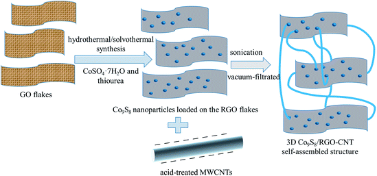
Herein, we report Co9S8 with graphene and CNT-based materials. On the one hand, the large specific surface of graphene can benefit the loading of Co9S8 nanoparticles;21 on the other hand, CNTs link the graphene sheets and form a intertwined, connected structure, which can make more paths for electrons and ions.
2 Experimental
2.1 Materials
Natural flake graphite and cobaltous sulfate heptahydrate (CoSO4·7H2O) were purchased from GuoYao Group Chemical Reagent Co., Ltd, China. Multiwalled carbon nanotubes (MWCNTs) were purchased from Beijing TianNai Co., Ltd, China. Sulphuric acid, potassium permanganate, hydrogen peroxide, thiourea, potassium nitrate, ammonia and glucose were purchased from Beijing Chemical Factory; all these reagents were of analytical grade.2.2 Synthesis of Co9S8/RGO-CNT composites
GO was prepared by modified Hummers' method, and MWCNTs were acid-treated with concentrated H2SO4 (60 mL) and KNO3 (1.5 g) at 70 °C for 7 h.22–25 As for Co9S8/RGO-CNT composite synthesis, about 1.2 g CoSO4·7H2O was dissolved in 30 mL of ethylene glycol (EG) and 10 mL of deionized water under stirring, then about 0.6 g thiourea was dispersed into this scarlet-red solution. About 65 mg of GO was dissolved in the aforementioned scarlet-red solution through sonication for 1 h. Then, 2 mL ammonia and 0.1 g glucose were added into the mixed solution, which was then transferred into a 50 mL Teflon-lined stainless-steel autoclave and heated in an oven at 170 °C for 10 h. After cooling to room temperature naturally, Co9S8/RGO powder was finally obtained by centrifugation, washing thoroughly with DI water and ethanol repeatedly, and drying at 60 °C for 7 h in a vacuum oven. Next, CNTs were added into the Co9S8/RGO aqueous solution through vacuum filtration and sonication. For self-assembly of the Co9S8/RGO-CNT composite, Co9S8/RGO and surface-modified CNTs (Co9S8/RGO![[thin space (1/6-em)]](https://www.rsc.org/images/entities/char_2009.gif) :
:![[thin space (1/6-em)]](https://www.rsc.org/images/entities/char_2009.gif) CNTs = 3
CNTs = 3![[thin space (1/6-em)]](https://www.rsc.org/images/entities/char_2009.gif) :
:![[thin space (1/6-em)]](https://www.rsc.org/images/entities/char_2009.gif) 1 wt ratio) were dispersed evenly with the addition of 3 mg CTAB in 100 mL of DI water under sonication for 2 h. Then, the solution was vacuum-filtrated with a polytetrafluoroethylene (PTFE) membrane, pore size = 0.2 μm, and self-assembled Co9S8/RGO-CNT film was formed during the filtration process and designated as 30% CNT. Two other Co9S8/RGO-CNT composites were prepared by changing the amount of CNTs (10 wt% and 50 wt%), and the samples were designated as 10% CNT and 50% CNT, respectively. For comparison, pure Co9S8/RGO was also prepared following the same procedure in the absence of CNTs.
1 wt ratio) were dispersed evenly with the addition of 3 mg CTAB in 100 mL of DI water under sonication for 2 h. Then, the solution was vacuum-filtrated with a polytetrafluoroethylene (PTFE) membrane, pore size = 0.2 μm, and self-assembled Co9S8/RGO-CNT film was formed during the filtration process and designated as 30% CNT. Two other Co9S8/RGO-CNT composites were prepared by changing the amount of CNTs (10 wt% and 50 wt%), and the samples were designated as 10% CNT and 50% CNT, respectively. For comparison, pure Co9S8/RGO was also prepared following the same procedure in the absence of CNTs.
2.3 Characterization
The physical properties of the Co9S8/RGO-CNT were examined with X-ray diffraction (XRD), cold cathode analytical field emission scanning electron microscopy (FESEM), transmission electron microscopy (TEM) and X-ray photo-electron spectroscopy (XPS).XRD analysis was obtained with a Rigaku D/max-2200 with Cu Kα radiation as X-ray source. The SEM images were taken via a JSM-7500F for morphological analysis. TEM images were obtained xEI Tecnai G2 F20 microscope. The chemical state and composition of the composites were measured by XPS via an ESCALab 220i-XL spectrometer with a monochromated Al K radiation (1486.6 eV).
2.4 Electrochemical measurements
The electrochemical performance of the Co9S8/RGO-CNT electrode was analyzed in a three-electrode cell including a Pt wire as the counter electrode, saturated calomel electrode (SCE) as the reference electrode, a 1 M KOH aqueous solution as the electrolyte and the Co9S8/RGO-CNT film loaded on Ni foam (1.0 cm × 1.0 cm) directly as the working electrode.Herein, cyclic voltammetry (CV) experiments, electrochemical impedance spectroscopy (EIS) and galvanostatic charge–discharge curves were performed using a CHI 660E electrochemical workstation. CV measurements were conducted at a scan rate of 10 mV s−1 with the voltage range of −0.1 V to 0.6 V. EIS tests were performed at open-circuit potential in the frequency range between 100 kHz and 0.01 Hz under a perturbation amplitude of 5 mV. Galvanostatic charge–discharge analysis was carried out at various current densities with the voltage range of −0.1 V to 0.3 V. All electrochemically characterized data for each composite given in the report were obtained under identical conditions at room temperature.
The specific capacitance (C) of the electrode can be calculated according to the following equation,
 | (1) |
3 Results and discussion
3.1 Structural and morphological characterization of Co9S8/RGO-CNT
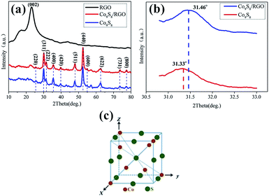
The composition and purity of the obtained Co9S8 sample is shown in Fig. 2a–c. All of the diffraction peaks in this pattern can be readily indexed to face-centered cubic Co9S8 (JCPDS card no. 65-6801). The crystal structure of Co9S8 is shown in Fig. 2c, where the S atoms are arranged through cubic close-packing, atoms are surrounded by a tetrahedron of atoms, and
  atoms are surrounded by an octahedron of S atoms.26–28 Comparing the diffraction peaks of the Co9S8 and Co9S8/RGO samples, there are some differences shown in Fig. 2b; the diffraction peaks of the plane (222) between two samples are different from 2θ and the peak's value, which may be caused by the addition of graphene, and which may prove that there might be some kinds of molecular forces between Co9S8 and RGO sheets. The crystal size grown on the surface of the RGO could be calculated by the Scherrer equation:
 | (2) |
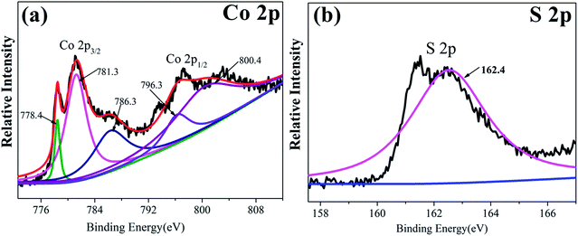
More detailed elemental analysis of the Co9S8/RGO sample was done by XPS. Fig. 3a and b shows the core level spectra of the Co 2p and S 2p region. The Co 2p spectrum, including Co 2p3/2 and Co 2p1/2, suggest the two spin–orbit doubles characteristic of Co2+ and Co3+.29–31 The S 2p peak at 161.9 eV is the binding energy of Co–S.32,33 The Co 2p and S 2p peaks in the XPS patterns are characteristic of Co9S8.33
The microstructures and morphologies of the Co9S8/RGO-CNT composite were investigated by SEM. As shown in Fig. 4a, the Co9S8 nanoparticles were scattered evenly with a size of about 50 nm on the RGO sheets, and the Co9S8 particles are microspheres; it is noteworthy that the particles are uniformly anchored on RGO sheets. The small size and homogenous distribution of Co9S8 particles in the Co9S8/RGO composite could be attributed to the functional groups on RGO acting as the nucleation sites for Co9S8 particles. Fig. 4b–d present SEM images of Co9S8/RGO composite with different contents of CNTs. It can been seen easily that Co9S8/RGO is well dispersed in the CNT network in Fig. 4c, while in Fig. 4b, part of the Co9S8/RGO is out of the CNT network, and in Fig. 4d, lots of CNTs are intertwined together, thus resulting in aggregation. To sum up, it is concluded that proper CNTs added into the Co9S8/RGO composite are extremely significant. With Co9S8/RGO evenly scattered in the highly conductive CNT network, the 3D hierarchical structure can provide a robust electrical connection within the entire electrode framework, enable the contact with the liquid electrolyte readily, and even maintain such features during the cycling process because of the 3D wrapping effect of the CNTs.34
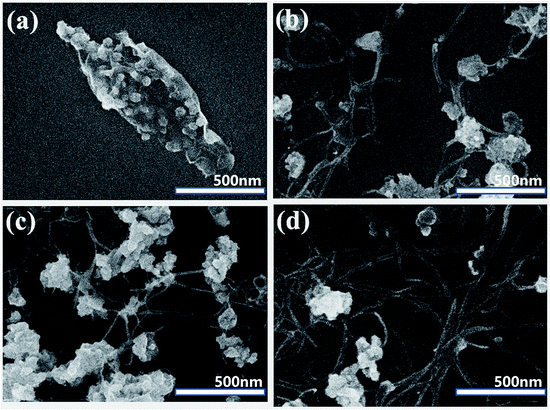 | ||
| Fig. 4 SEM images of Co9S8/RGO (a), Co9S8/RGO-10% CNT (b), Co9S8/RGO-30% CNT (c) and Co9S8/RGO-50% CNT (d). CNT and graphene sheets intertwine and form an interconnected structure. | ||
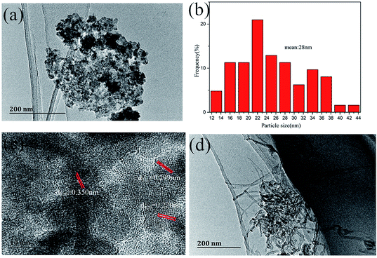
Further microstructures of the Co9S8/RGO-CNT composite were characterized by TEM. From Fig. 5a and b, it can be observed that Co9S8 particles are well dispersed on the RGO sheets, while aggregation occurred in a portion of the area. Fig. 5c is the high-resolution TEM (HRTEM) image of Co9S8/RGO, and it indicates Co9S8 particles with a d-spacing of 0.350 nm, 0.299 nm and 0.220 nm, which correspond to the (220), (311) and (420) planes of Co9S8, respectively. As for the TEM image of the Co9S8/RGO-CNT composite in Fig. 5d, it is noteworthy that Co9S8/RGO groups are connected to each other by CNTs. The results indicate that with the unique structural properties of RGO and highly conductive nature of uniformly interconnected CNT network, such continuous interconnected network finally can render well-developed porous structures, high mechanical strength, and superior flexibility of the Co9S8/RGO-CNT composites, and hence can be considered as an ideal electrode material in supercapacitors.35,36
3.2 Electrochemical characterization of Co9S8/RGO-CNT
The capacitive properties of the composite materials were assessed by CV, galvanostatic charge–discharge and EIS measurements.Fig. 6a–d shows the CV curves of pure Co9S8/RGO and Co9S8/RGO-CNT with the voltage range of −0.1 V to 0.6 V and various scan rates ranging from 5 mV s−1 to 50 mV s−1. The CV curves of Co9S8 and Co9S8/RGO-CNT have two nearly reversible and symmetrical redox peaks, indicating good capacitive behavior. Though there is no unified conclusion explaining the reaction mechanism of Co9S8, it is reported that Co9S8 may react with the form between Co2+, Co3+ and Co4+, and it can be described as the following reaction:37
| Co9S8 + OH− → Co9S7OH + e− | (3) |
| Co9S7OH + OH− → Co9S6(OH)2 + e | (4) |
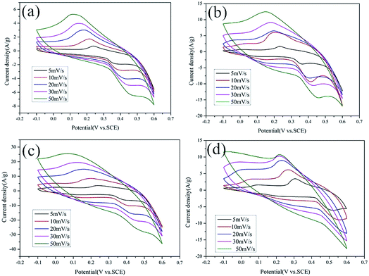 | ||
| Fig. 6 CV curves of pure RGO (a), Co9S8 (b), Co9S8/RGO (c) and Co9S8/RGO-CNT (d) at different scan rates in a three-electrode system. | ||
The specific capacitance of Co9S8/RGO was calculated by CV curves using a standard equation as stated in the Experimental section. The highest specific capacitance of RGO, Co9S8 and Co9S8/RGO was found to be 243.99 F g−1, 541.99 F g−1 and 709.25 F g−1, respectively, while that of Co9S8/RGO-CNT is 1376.78 F g−1 at scan rate of 5 mV s−1; it was also found to decrease with increasing current density. The reduction of specific capacitance may be attributed to the reduced ion concentration between the electrolyte and electrode interface.
The charge–discharge cycles of Co9S8/RGO and Co9S8/RGO-CNT are shown in Fig. 7a–d, which were carried out at various current densities between 0.5 A g−1 and 4 A g−1 and at the voltage range of −0.1 V to 0.3 V in 1 M KOH electrolyte. The charge–discharge curves show a nearly symmetrical and linear shape, presenting good supercapacitive behaviors.
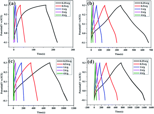 | ||
| Fig. 7 The galvanostatic charge–discharge curves of pure RGO (a), Co9S8 (b), Co9S8/RGO (c) and Co9S8/RGO-CNT (d) at various current densities in the three-electrode system. | ||
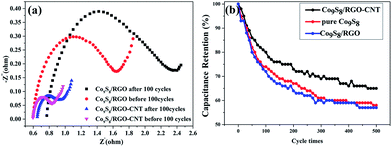
The electrochemical impedance measurements were carried out at the frequency range of 100 kHz to 0.01 Hz, as shown in Fig. 8a. It can be easily observed that the Nyquist plots before and after 100 cycles consist of a semi-circle in the high frequency and a straight line in the low frequency, which is the typical feature of capacitive behavior and characteristic of ion diffusion in the electrode. Comparing the curve of Co9S8/RGO with Co9S8/RGO-CNT before 100 cycles, the radius of the semi-circle of Co9S8/RGO-CNT is much smaller than that of Co9S8/RGO, which is attributed to the Co9S8/RGO-CNT composites' interconnected structure and better conductive performance. At the low-frequency district, the slope of Co9S8/RGO is lower than that of Co9S8/RGO-CNT, indicating that the interface impedance of Co9S8/RGO-CNT is less, which shows its better conductive performance. As for the high-frequency district, the radius of the semicircle represents charge transfer impedance, and the larger the radius, the greater the impedance and the lower the charge transfer.13,28,29 Therefore, it is concluded that Co9S8/RGO-CNT is better than Co9S8/RGO.
Long cycling behavior is a major factor for the practical application of supercapacitors, and the values of specific capacitance after 500 cycles are shown in Fig. 8b. From the curves, the specific capacitance retention ratio of Co9S8/RGO is 55% after 500 cycles, while the Co9S8/RGO with 30% CNT is 65%, which shows better cycling stability.
4 Conclusions
In summary, we have successfully synthesized Co9S8/RGO-CNT using hydrothermal and vacuum-filtration methods. SEM and TEM images show that the morphologies of Co9S8/RGO-CNT have a unique 3D structure caused by graphene and CNTs interconnected together. Moreover, the excellent electrochemical performance of Co9S8/RGO-CNT composites is attributed to the conductive 3D interconnected network composed by interconnected graphene sheets and CNTs, which provide a fast and continuous highway for electron and ion transfer and accommodate the load of Co9S8 particles during charge/discharge cycling. The unique structure can guarantee a better specific capacitance as well as charge–discharge and long-term stability, which shows a good prospect for the future. The highest specific capacitance of Co9S8/RGO-CNT is 1376.78 F g−1 at the scan rate of 5 mV s−1, and the specific capacitance of Co9S8/RGO-CNT is 894.9 F g−1 after 500 cycles. The outstanding electrochemical properties of Co9S8/RGO-CNT suggest that it is a promising electrode material for supercapacitors.Acknowledgements
The authors of this study gratefully acknowledge Beihang University MSE School for the TEM and SEM. Many thanks also go to Dr Li Ye, Dr Han Xiao and Dr Zhao Xiaoran for their helpful input.Notes and references
- X. Li, X. Wang, L. Zhang, S. Lee and H. Dai, Science, 2008, 319, 1229–1232 CrossRef CAS PubMed.
- F. Bonacco, L. Colombo and G. H. Lu, et al., Science, 2015, 347, 1246501–1246509 CrossRef PubMed.
- B. Wang, J. Mater. Chem., 2012, 229, 15750–15756 RSC.
- G. Q. Zhang, H. B. Wu, H. E. Hoster, M. B. Chan-Park and X. W. Lou, Energy Environ. Sci., 2012, 5, 9453–9456 CAS.
- X. Y. Dong, L. Wang, D. Wang, C. Li and J. Lin, Langmuir, 2012, 28, 293–298 CrossRef CAS PubMed.
- M. M. Yao, Z. H. Hu, Z. J. Xu and Y. F. Liu, J. Alloys Compd., 2015, 644, 721–728 CrossRef CAS.
- L. Huang, D. C. Chen, Y. Ding, S. Feng, Z. L. Wang and M. L. Liu, Nano Lett., 2013, 13, 3135–3139 CrossRef CAS PubMed.
- M. D. Stoller, S. Murali, N. Quarles, Y. W. Zhu, J. R. Potts, X. J. Zhu, H. W. Ha and R. S. Ruoff, Phys. Chem. Chem. Phys., 2012, 14, 3388–3391 RSC.
- T. C. Liu, W. G. Pell and B. E. Conway, Electrochim. Acta, 1997, 42, 3541–3552 CrossRef CAS.
- G. Rajeshkhanna, E. Umeshbabu, P. Justin and G. R. Rao, Int. J. Hydrogen Energy, 2015, 40, 12303–12314 CrossRef CAS.
- L. Chuan, A. James and N. Branko, J. Electrochem. Soc., 1998, 145, 4097–4101 CrossRef.
- J. Cheng, B. Wang and H. L. Xin, et al., J. Mater. Chem. A, 2013, 1, 10814–10820 CAS.
- L. Cao, L. B. Kong and Y. Y. Liang, et al., Chem. Commun., 2004, 14, 1646–1647 RSC.
- P. Simon and Y. Gogotsi, Nat. Mater., 2008, 7, 845–854 CrossRef CAS PubMed.
- W. Chen, S. Li, C. Chen and L. Yan, Adv. Mater., 2011, 23, 5679–5683 CrossRef CAS PubMed.
- M. Pumera, Energy Environ. Sci., 2011, 3, 668–674 Search PubMed.
- W. Chen and L. Yan, Nanoscale, 2011, 3, 3132–3137 RSC.
- S. Niu, W. Lv, C. Zhang, Y. Shi, J. Zhao, B. Li, Q.-H. Yang and F. Kang, J. Power Sources, 2015, 295, 182–189 CrossRef CAS.
- X. L. Jia, Z. Chen, X. Cui, Y. T. Peng, X. L. Wang, G. Wang, F. Wei and Y. F. Lu, ACS Nano, 2012, 6, 9911–9919 CrossRef CAS PubMed.
- Y. Wang, Y. P. Wu, Y. Huang, F. Zhang, X. Yang, Y. F. Ma and Y. S. Chen, J. Phys. Chem. C, 2011, 115, 23192–23197 CAS.
- Q. Cheng, J. Tang, J. Ma, H. Zhang, N. Shinya and L. C. Qin, Phys. Chem. Chem. Phys., 2011, 13, 438–444 RSC.
- N. Jha, P. Ramesh, E. Bekyarova, M. E. Itkis and R. C. Haddon, Adv. Energy Mater., 2012, 2, 438–444 CrossRef CAS.
- K. Y. Ma, J. P. Cheng, F. Liu and X. B. Zhang, J. Alloys Compd., 2016, 679, 277–284 CrossRef CAS.
- G. X. Wang, J. Yang, J. Park, X. L. Gou, B. Wang, H. Liu and J. Yao, J. Phys. Chem. C, 2008, 112, 8192–8195 CAS.
- M. C. Liu, Y. Zhao, S. Gao, Y. Wang, Y. X. Duan, X. Han and Q. Dong, New J. Chem., 2015, 39, 1094–1100 RSC.
- H. Jiang, C. Z. Li, T. Sun and J. Ma, Nanoscale, 2012, 4, 807–812 RSC.
- C. H. Zheng and T. Yao, et al., J. Alloys Compd., 2016, 678, 93–101 CrossRef CAS.
- J. Pu, Z. H. Wang, K. L. Wu, N. Yu and E. H. Sheng, Phys. Chem. Chem. Phys., 2014, 16, 785–791 RSC.
- R. B. Rakhi, N. A. Alhebshi, D. H. Anjum and H. N. Alshareef, J. Mater. Chem. A, 2014, 2, 16190–16198 CAS.
- J. F. Li, S. L. Xiong, Y. R. Liu, Z. C. Ju and Y. Qian, ACS Appl. Mater. Interfaces, 2013, 5, 981–988 CAS.
- P. F. Yin, L. L. Sun, Y. L. Gao and S. Y. Wang, Bull. Mater. Sci., 2008, 31, 593–596 CrossRef CAS.
- R. Ramachandram, M. Saranya, C. Santhosh, V. Velmurugan, B. P. C. Raghupathy, S. K. Jeong and A. N. Grace, RSC Adv., 2014, 421151–451162 Search PubMed.
- S. J. Bao, Y. B. Li, C. M. Li, Q. L. Bao, Q. Lu and J. Guo, Cryst. Growth Des., 2008, 83745–83749 Search PubMed.
- S. Peng, L. Li, X. Han, W. Sun and M. Srinivasan, Angew. Chem., Int. Ed., 2014, 53, 12594–12599 CAS.
- F. Fu, Y. Chen, P. Li, J. He, Z. Wang, W. Lin and W. Zhang, RSC Adv., 2015, 5, 71790–71795 RSC.
- M. Zhou, T. Tian, X. Li, X. Sun, J. Zhang, Y. Chen, P. Cui, J. Tang and L. C. Qin, Chem. Phys. Lett., 2013, 581, 64–69 CrossRef CAS.
- X. Zhang, D. Zhao, P. Tang, Y. Shen, C. Xu, H. Lia and Y. Xiao, J. Mater. Chem. A, 2013, 1, 3706–3712 CAS.
Footnote |
| † Electronic supplementary information (ESI) available. See DOI: 10.1039/c6ra27685g |
| This journal is © The Royal Society of Chemistry 2017 |

