 Open Access Article
Creative Commons Attribution 3.0 Unported Licence
An alkaline direct oxidation glucose fuel cell using three-dimensional structural Au/Ni-foam as catalytic electrodes
Jinyao Chen *,
Hao Zheng,
Jian Kang*,
Feng Yang,
Ya Cao and
Ming Xiang
Key State Laboratory of Polymer Materials Engineering, Polymer Research Institute of Sichuan University, Chengdu 610065, People's Republic of China. E-mail: chenjinyao@scu.edu.cn; jiankang@scu.edu.cn; Tel: +86-028-85406333
First published on 12th January 2017
Abstract
Glucose is an ideal fuel for fuel cells because it is abundant in nature, renewable, non-toxic and easy to produce. Glucose fuel cells using enzymes and microbes as the catalysts are limited by their very poor performance and rather short durability. In this work, a direct oxidation glucose fuel cell using an anion-exchange membrane and three-dimensional structural Au/Ni foam electrodes is developed. The effects of the concentration of glucose and KOH and operation temperature on the fuel cell performance are investigated. The results show that this type of direct oxidation glucose fuel cell with a relatively cheap membrane and non-platinum catalysts can produce a maximum power density of 26.6 mW cm−2 at a current density of 89 mA cm−2 with 0.5 M glucose and 6 M KOH at a temperature of 70 °C, which is favorable for large-scale use. The high performance of the fuel cell is attributed mainly to the increased kinetics of both the glucose oxidation reaction and oxygen reduction reaction, rendered by a better electrocatalytic activity of the Au/Ni foam and higher operating temperature.
1. Introduction
With the rapid growth of the global economy and population, the demand for energy is increasing. However, conventional fossil fuels, such as oil and coal, are non-renewable energy sources. In order to reduce the reliance on fossil fuels, the use of biomass as an energy source is becoming a viable way. As one of the most abundant sugars in nature, glucose can be obtained from a lot of residual biomass that is produced by agricultural activities and from special energy crops.1,2 At present, traditional methods for obtaining energy from glucose involve producing ethanol and converting into hydrogen, but these methods are hampered by economic and technical issues.3,4 Another approach to obtaining energy from glucose is to feed it into a fuel cell to yield electricity. By this way, the chemical energy of glucose can be directly changed to electrical energy with less energy loss.Lots of work on glucose as a fuel for direct oxidation fuel cell, including enzymatic and microbial fuel cells (MFC), has been done over the past decades.4–10 As an important application of a biofuel cell, direct oxidation glucose fuel cell has been explored to supply the necessary energy for implanted medical devices.11,12 For this type of enzymatic glucose fuel cells, the most critical issue is its very poor performance. Furthermore, it is difficult to keep the activity of enzyme and the stability of power output because enzymes are proteins that typically have a limited lifetime, even in a buffer solution.4,6 In MFCs, the chemical energy of glucose is converted to electrical energy by the catalytic reaction of microorganisms. MFCs have relatively long-term lifetimes and complete oxidation of glucose.6 However, the performance of microbial fuel cells is also very poor because there is the most key hurdle that it is very difficult for electron to transfer from the microbe to the electrode. The power density is only about 0.43 mW cm−2 at the voltage of about 0.66 V.13
Because of the above-described problems of enzymatic and microbial fuel cells, direct oxidation glucose fuel cells that use metal catalysts and alkaline medium have been explored.14–16 Using a noble metal catalyst such as platinum (Pt) and alkaline solution instead of the enzymes and microbes, some recent reports revealed the possibility to improve the performance of the glucose fuel cell.3,14 Benefiting from their biocompatibility and long-term stability, these noble metals are suitable catalysts for the glucose fuel cell. As reported, a maximum power density of 3.0 mW cm−2 and an open-circuit voltage (OCV) of 1.08 V can be obtained at room temperature for alkaline glucose fuel cell with the glucose concentration of 1.85 M and the KOH concentration of 7.0 M when using PtCo and Pt as the anode and cathode catalysts.14
For a direct oxidation glucose fuel cell, the membrane separating the cathode and the anode can be either proton exchange membranes (PEM, typically Nafion) or anion exchange membranes (AEM).3,15–18 Some reports showed the performance of the glucose fuel cell can be remarkably improved when an acidic electrolyte is changed into an alkaline, i.e., an anion-exchange membrane.3,16 Fujiwara et al. compared the cell performance between an AEM-glucose fuel cell and a PEM-glucose fuel cell using the Pt black and PtRu black as the cathode and anode catalysts. The performance of the glucose fuel cell significantly improved from 1.5 to 20 mW cm−2 when an AEM replaced a PEM.3 The improvement of the cell performance is beneficial from the enhanced kinetics of the glucose oxidation reaction (GOR) and oxygen reduction reaction (ORR) in an alkaline media compared with those in an acidic media.19
However, the high cost and low catalytic stability caused by catalyst poisoning are critical obstacles for large-scale use of glucose fuel cell using the noble Pt as catalysts. Therefore, non-Pt metals with long lifetime and operational stability, including Au, Ag, Ni, Pd and manganese oxide were considered as catalysts in direct oxidation glucose fuel cells.19–27 Au is a primary candidate as catalysts in alkaline glucose fuel cells, due to its high electrocatalytic activity for glucose oxidation and oxygen reduction without observable self-poisoning. Compared to the other metals, the oxidation potential of Au in neutral and alkaline medium is more negative and therefore Au as catalysts for the oxidation of glucose has been extensively examined.28–38 Based on the observed phenomena that a gold oxide layer formed on the surface of a gold electrode could have a great catalytic effect on the oxidation of glucose, Nikolaeva et al. proposed a mechanism for glucose electrooxidation at high potentials.39 Cui et al. investigated the complex oxidation of glucose at the surface of gold electrodes in different conditions of pH, buffer and halide concentration.40 Liu et al. investigate the performance of the gold electrode for glucose oxidation in the presence of glucose at different concentrations by cyclic-voltammetric techniques.41 They found that a positive current peak due to the presence of glucose occurred during the cathodic sweep. The current values had a highly linear dependence on the concentration of glucose in several regions, depending on the medium composition. The above investigations indicated that it is feasible for using Au as catalysts in alkaline medium for a direct oxidation glucose fuel cell. As far as we know, there are few studies on a direct glucose fuel cell that uses an anion-exchange membrane and Au catalytic electrodes at the anode and cathode.42–44
In this study, to develop a novel electrode with good catalytic and mass transport properties for a direct oxidation glucose fuel cell, nickel foam was chosen as a substrate material of the electrode, and Au was used as an active catalytic component. Because of its three dimensional (3D) network structure with high porosity, nickel foam has better transport and diffusion of reactants (such as glucose) to the electro-catalyst surfaces. Au/Ni foam electrodes with good catalytic performance and transport properties were prepared by a spontaneous deposition of Au particles onto nickel foam surface, and the performance of an alkaline glucose fuel cell using such an Au/Ni-foam electrode as both the anode and the cathode was investigated.
2. Experimental
2.1 Preparation of Au/Ni-foam electrode
Au/Ni-foam composite electrodes were prepared by a simple spontaneous deposition of Au particles onto the surface of nickel foam.45 In order to clean and activate the surface, Ni foams (110 ppi, 320 g m−2 and 95% porosity, 0.5 mm in thickness, Changsha Lyrun New Material Co. Ltd., China) were pretreated with acetone, 6.0 M HCl, and deionized water for 15 min step by step prior to use. The Au particles were deposited on the surface of Ni foam by dipping the pretreated Ni foam substrate into an aqueous solution of AuCl3 (Alfa Aesar, Premion®, 99.99%) with the concentration of 4 mM for 60 s at room temperature. Hereafter, the electrode was remove from the solution, and rinsed with deionized water thoroughly. The resulting electrodes were stored in 2 M KOH till use. All solutions were made with analytical grade chemical reagents and deionized water. The morphology of the Au/Ni-foam electrode was characterized using a scanning electron microscopy (SEM, JEOL JSM-5900LV) under an accelerating voltage of 20 kV.2.2 Pretreatment of anion exchange membrane
Anion exchange membranes (Fumasep™ FAB) were purchased from Fuma-Tech, Germany. AEMs were pretreated using acetone, deionized water and 3 wt% KCl solution for 30 min step by step. Then the pretreated membranes were kept in 3 wt% KCl solution till use.2.3 Glucose fuel cell set-up and instrumentation
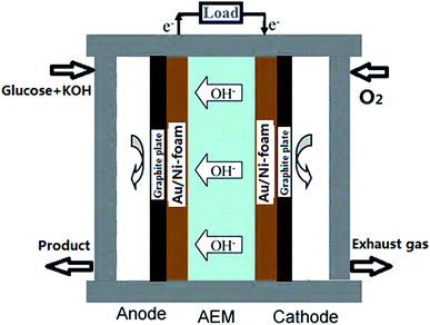
A schematic image of AEM-glucose fuel cell is shown in Fig. 1. Au/Ni-foams with a geometrical area of 4 cm2 were used as the anode and the cathode of the glucose fuel cell. The sandwich structure of anode/membrane/cathode was compressed between two graphite block current collectors with a serpentine flow field. Both flow-fields were made from the stainless-steel plate, in which a single serpentine flow channel, 2.0 mm wide and 1 mm deep. The electrolyte including glucose and KOH was fed into the anode at various flow rate controlled by a peristaltic pump, while pure oxygen was fed to the cathode at a flow rate of 500 standard cubic centimeter per minute (sccm) measured by a mass flow controller (Omega FMA-7105E). In addition, the operating temperature was controlled by two electrical heating rods installed in the cell fixtures and measured with a thermocouple located at the anode current collector.2.4 Polarization curve measurement
The cell polarization curves were measured using a CHI 650E electrochemical analyzer (Shanghai Chenhua Instrument Inc., China). The internal resistance of the cell was measured by the built-in function of CHI 650E electrochemical analyzer. The glucose fuel cell was allowed to build a equilibrium at open circuit for about 1 hour, until the stable open circuit potential was obtained.3. Results and discussion
3.1 The morphology of Au/Ni-foam electrode
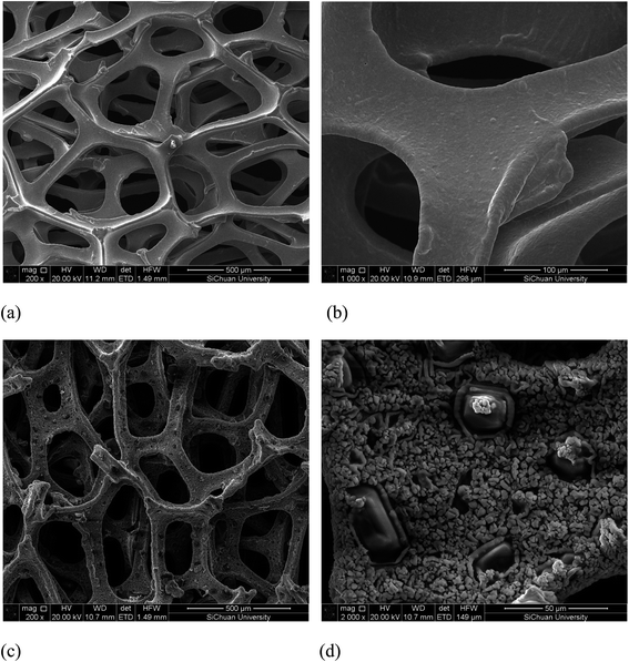
The SEM images of the nickel foam and Au/Ni-foam electrode are shown in Fig. 2. It can seen from Fig. 2(a) and (b) that a three dimensional microporous and cross-linked skeleton structure with a smooth surface is observed in the SEM images of the Ni foam used in this work. Fig. 2(c) and (d) display the SEM images of deposited Au particles onto the Ni foam. It can be seen that Au grains with a size range of 3–10 μm densely covered the Ni foam surface. Comparing with the conventional electrodes generally used in fuel cells, the Au/Ni-foam electrode with such 3D micropore integrated structures should have better mass transport property and enhancing electrochemical reaction rates due to short mass transfer lengths allowing liquid and gas species reacting efficiently at the electrode/electrolyte interface.3.2 Performance of alkaline glucose fuel cell with Au/Ni-foam electrodes
In this study, the prepared Au/Ni-foams are used as the catalytic electrodes at the anode and cathode. Liu et al.41 had investigated the performance of the gold electrode in the presence of glucose at different concentrations by cyclic-voltammetric techniques. Based on the cyclic voltammetric results, they proposed the following electrocatalytic oxidation mechanism of glucose in KOH solution at the gold electrode surface.
 | (1) |
 | (2) |
This reaction can be described as eqn (3) by rapid electrochemical regeneration of the oxide of gold surface.
| AUnOm−1 + 2OH− ⇌ AUnOm + H2O + 2e− | (3) |
N. Fujiwara et al.3 proposed the anodic reaction of AEM glucose fuel cell using Pt catalysts, as described by eqn (4).
| C6H12O6 (glucose) + 2OH− → C6H12O7 (gluconic acid) + H2O + 2e− | (4) |
Therefore, it is obvious that the reaction mechanism is the same for both Pt and Au catalyst. Therefore, the anodic, cathodic and total reactions for an alkaline glucose fuel cell using such an Au/Ni-foam electrode can be described as following:
Anode:
| C6H12O6 (glucose) + 2OH− → C6H12O7 (gluconic acid) + H2O + 2e− | (5) |
Cathode:
| ½O2 + H2O + 2e− → 2OH− | (6) |
Overall:
| C6H12O6 (glucose) + ½O2 → C6H12O7 (gluconic acid) | (7) |
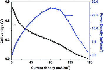
Fig. 3 shows the polarization and power density curves of alkaline direct oxidation glucose fuel cells with Au/Ni-foams electrode as both the anode and the cathode. It can be seen from Fig. 3 that no retrogradation is found, indicating that Au/Ni foams have no catalyst poisoning effect as observed in Pt-based glucose fuel cells. When the experiment was performed at 70 °C, a peak power density of 26.6 mW cm−2 is achieved at a current density of 89 mA cm−2, with 0.5 M glucose solution mixed with 6.0 M KOH pumped into the anode at a flow rate of 10 mL min−1 and with dry pure oxygen fed to the cathode at a flow rate of 500 sccm. It was reported3 that a maximum power density of 20 mW cm−2 could be reached for an AEM-glucose fuel cell which consisted of PtRu/C and Pt/C as the anode and cathode catalysts. The higher performance of glucose fuel cell in this study may be attributed to the better mass transport property and the superior electrocatalytic activity of Au/Ni foam electrodes for the glucose oxidation reaction (GOR) and the oxygen reduction reaction (ORR) in the alkaline medium.
3.3 Effect of glucose concentration on the performance of AEM-glucose fuel cell
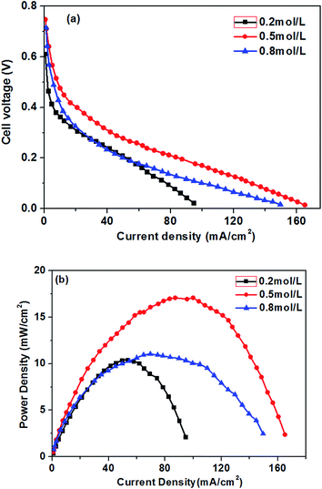
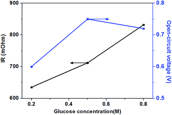
The effect of different glucose concentrations on the cell performance with at a KOH concentration of 0.5 M is shown in Fig. 4. With increasing glucose concentration from 0.2 to 0.5 M, the performance of the AEM-glucose fuel cell enhances, and the limiting current density of the cell is improved from 95 to 165 mA cm−2. The cell performance dropped with further increasing in glucose concentration. Hence, a maximum power density of 17.1 mW cm−2 is obtained with an optimum glucose concentration of 0.5 M, as shown in Fig. 4. The reason for these phenomena is as follows. The potential of the anode depends on the local concentrations of both glucose and hydroxyl ions in the anode catalyst layer for a given anode catalyst. A change in either one of these concentrations causes to a change in the other. Increasing the glucose concentration from 0.1 to 0.5 M results in an increasing glucose concentration and a reduction concentration of the hydroxyl ions at the anode catalyst layer. In order to ensure the better progress of GOR, however, the concentration of hydroxyl ions must still be kept at an appropriate level. Therefore, the increase in the glucose concentration leads to the enhanced kinetics of GOR, which reduces the activation loss of the anode, and the cell voltages are improved, as confirmed by open circuit voltage (OCV) in Fig. 5. In addition, the mass transport polarization can be also decreased with the increase in the glucose concentration, which further improves the performance of the glucose fuel cell. It should be noteworthy that the increase in the glucose concentration will raise the internal cell resistance because of the increased mass transport resistance of hydroxyl ions, which leads to an increase of the ohmic loss. The improvement of the activation and mass transport properties in the anode due to the increased glucose concentration, however, not only recompense the increased ohmic loss but also enhance the performance of the glucose fuel cell. Therefore, the performance of the AEM-glucose fuel cell improves when increasing the glucose concentration from 0.2 to 0.5 M.When further adding the glucose concentration to 0.8 M, however, the cell performance is decreased. This is mainly because the glucose concentration will be much higher at the active surfaces of the catalytic electrodes corresponding to the relatively low concentration of hydroxyl ions caused by 1.0 M KOH, which leading to the less adsorption of hydroxyl ions on the active site. Hence the electrochemical kinetics is decreased and the OCV of the fuel cell is lowered, as shown in Fig. 5, and the cell performance is reduced.46 On the other hand, a barrier created by the high concentration of the glucose solution may hinder the transfer of hydroxyl ions and therefore give rise to an increase in internal cell resistance (shown in Fig. 5), leading to a decline of the cell performance. Therefore, the cell performance declines with further increasing the glucose concentration from 0.5 to 0.8 M, due to the reduced electrochemical kinetics and the large ohmic loss.
3.4 Effect of KOH concentration on the performance of AEM-glucose fuel cell
Fig. 6 presents the curves of the fuel cell voltage and power density against the current density measured at various KOH concentration and a given glucose concentration of 0.5 M. With increasing the current density, the cell voltage decreases quickly and linearly, indicating that the reduced performance of the glucose fuel cell results mainly from the electrochemical polarization in the low current density region (below 30 mA cm−2). The concentration polarization caused by mass transport is not observed even at current densities higher than around 160 mA cm−2, which indicating that the electrodes have superior mass transport property, avoiding the occurrence of the concentration polarization.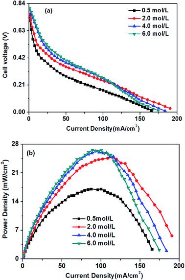 | ||
| Fig. 6 Effect of KOH concentrations on cell performance. Anode: 0.5 M glucose containing various KOH concentration aqueous solutions, 10 mL min−1. Cathode: pure oxygen, 500 sccm. Temperature: 70 °C. | ||
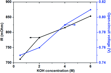
In the low and moderate current density region (below 120 mA cm−2), it can be found that the cell voltage increases with increasing KOH concentration. This is mainly attributed to the enhanced GOR kinetic caused by a higher KOH concentration, which resulting in the increase in the OCV of the fuel cell, as shown in Fig. 7. At the same time, with increasing KOH concentration, the internal cell resistance is raised from 712 to 854 mohm because the higher KOH concentration in the anode catalyst layer increase the mass transport resistance of hydroxyl ions from the cathode to anode, which resulting in the larger ohmic loss. However, the decrease of the cell voltage is predominated by the activation polarization at low current densities. Therefore, it can be found in Fig. 6 that the cell voltage monotonously improves with increasing KOH concentration due to the enhanced electrochemical kinetics.
Generally, the alkaline medium at the anode significantly influences not only the electrochemical kinetics, but also the move of the hydroxyl ion to the anode.46,47 The internal resistance of the glucose fuel cell increases with an increase in the KOH concentration, as presented in Fig. 7. In the AEM-glucose, the hydroxyl ions transfer from the cathode to the anode. A higher concentration of the hydroxyl ion in the anode catalyst layer caused by the increasing of KOH concentration at the anode hinders to transfer the hydroxyl ion from the cathode to the anode, which causing the larger transport resistance. The enhanced electrochemical kinetics of GOR due to the high KOH concentration, however, not only recompenses the increased ohmic loss, but also raises the cell performance in this current density range. Therefore, in low and moderate current density region the cell performance of this AEM-glucose fuel cell is improved with increasing KOH concentration from 0.5 to 4.0 M.
However, the cell performance is not further improved when further adding the KOH concentration from 4.0 to 6.0 M. This is mainly because that too high KOH concentration results in an excess cover of hydroxyl ions in the anode catalyst layer, which reducing the amount of sites in the catalyst layer available for glucose adsorption,48 thereby causing the decline of the cell performance. At the same time, the increase in the KOH concentration improves the internal cell resistance, as shown in Fig. 7, resulting in a greater ohmic loss and thus a poor performance of the glucose fuel cell.
In summary, the KOH concentrations remarkably affect the performance of the AEM-glucose fuel cell dependent on the current density. Because of the enhanced kinetics of the GOR with higher KOH concentration at low and moderate current densities, the cell performance is dominated by the increasing KOH concentration. In high current density regions, however, the high KOH concentrations in the anode deteriorate the cell performance. For a given current density region, too high a KOH concentration hinders the transport of hydroxyl ions from the cathode to the anode, which resulting in a larger ohmic loss and thus a poor cell performance; too low a KOH concentration decreases the GOR kinetics, which causing high activation polarization and thus poor cell performance.
3.5 Effect of operating temperature on the cell performance
Fig. 8 shows the influence of the operation temperatures on the fuel cell performance. As expected, the fuel cell performance improves with the increase of the operation temperature. When the operation temperature is increased from 23 to 70 °C, the limiting current density improves from 82 to 165 mA cm−2. The enhanced performance of the glucose fuel cell with increasing operation temperature is attributed mainly to faster electrochemical kinetics, enhanced mass transfer and increased conductivity of the hydroxyl ions.16 The kinetics of both the GOR and ORR in the glucose fuel cell can be enhanced by an increase in the operation temperature. The improvement of hydroxyl ion conductivity will decrease the ohmic polarization of the cell. Additionally, an increase in the operating temperature will improve the glucose and oxygen diffusivities in the catalyst layers, which causing the low mass transport polarization. Therefore, the operation temperature plays an important role on the cell performance.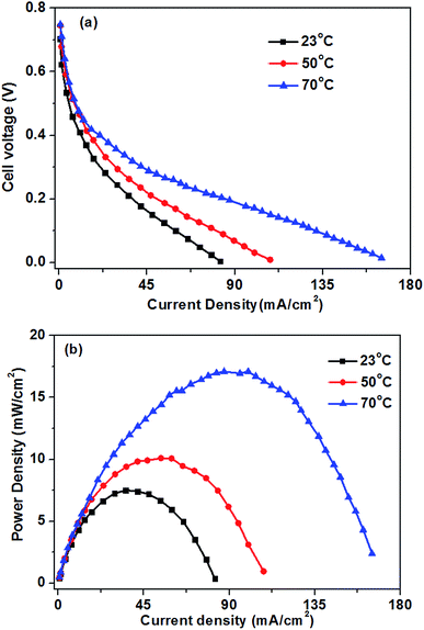 | ||
| Fig. 8 Effect of operation temperature on glucose fuel cell performance. Anode: 0.5 M glucose + 0.5 M KOH aqueous solution, 10 mL min−1. Cathode: pure oxygen, 500 sccm. | ||
4. Conclusions
Au/Ni-foam electrodes with three dimensional network structure were successfully prepared by simple spontaneous deposition of Au particles on nickel foam substrates. An alkaline glucose fuel cell with an anion-exchange membrane and Au/Ni-foam electrodes has been developed. The results also indicate that the performance of the glucose fuel cell is influenced significantly by operating parameters such as glucose concentration, KOH concentration and operating temperature. This type of direct oxidation glucose fuel cell with a relatively cheap membrane and non-platinum catalysts can produce a maximum power density of 26.6 mW cm−2 at a current density of 89 mA cm−2 on 0.5 M glucose and 6 M KOH at the temperature of 70 °C, which is favorable for large-scale use. The excellent performance of the glucose fuel cell is attributed mainly to the enhanced kinetics of both GOR and ORR, induced by a better electrocatalytic activity and mass transport property of Au/Ni foams and higher operating temperature.References
- S. K. Chaudhuri and D. R. Lovley, Nat. Biotechnol., 2003, 21, 1229 CrossRef CAS PubMed.
- Van Wyk and P. H. Jacobus, Trends Biotechnol., 2001, 19, 172 CrossRef PubMed.
- N. Fujiwara, S. Yamazaki, Z. Siroma, T. Ioroi, H. Senoh and K. Yasuda, Electrochem. Commun., 2009, 11, 390 CrossRef CAS.
- S. C. Barton, J. Gallaway and P. Atanassov, Chem. Rev., 2004, 104, 4867 CrossRef CAS PubMed.
- S. C. Barton, H. H. Kim, G. Binyamin and A. Heller, J. Am. Chem. Soc., 2001, 123, 5802 CrossRef CAS.
- H. H. Kim, Y. C. Zhang and A. Heller, Anal. Chem., 2004, 76, 2411 CrossRef CAS PubMed.
- S. Shleev, J. Tkac, A. Christenson, T. Ruzgas, A. I. Yaropolov, J. W. Whittaker and L. Gorton, Biosens. Bioelectron., 2005, 20, 2517 CrossRef CAS PubMed.
- R. A. Bullen, T. C. Arnot, J. B. Lakeman and F. C. Walsh, Biosens. Bioelectron., 2006, 21, 2015 CrossRef CAS PubMed.
- P. Pandey, V. N. Shinde, R. L. Deopurkar, S. P. Kale, S. A. Patil and D. Pant, Appl. Energy, 2016, 168, 706–723 CrossRef CAS.
- M. Ghasemi, M. Ismail, S. K. Kamarudin, K. Saeedfar, W. R. W. Daud, S. H. A. Hassan, L. Y. Heng, J. Alam and S. E. Oh, Appl. Energy, 2013, 102, 1050–1056 CrossRef CAS.
- E. Katz, A. F. Bueckmann and I. Willner, J. Am. Chem. Soc., 2001, 123, 10752 CrossRef CAS PubMed.
- I. Willner, Science, 2002, 298, 2407 CrossRef CAS PubMed.
- K. Rabaey, N. Boon, S. D. Siciliano, M. Verhaege and W. Verstraete, Appl. Environ. Microbiol., 2004, 70, 5373 CrossRef CAS PubMed.
- K. Y. Chan, X. Zhan, C. M. Lam, M. Chung, A. C. C. Tseung, P. K. Shen and J. K. You, US 7,419,580 B2, Methods and apparatus for the oxidation of glucose molecules, September 15, 2009.
- L. An, T. S. Zhao, S. Y. Shen, Q. X. Wu and R. Chen, J. Power Sources, 2011, 196, 186–190 CrossRef CAS.
- Y. S. Li, T. S. Zhao and Z. X. Liang, J. Power Sources, 2009, 187, 387–392 CrossRef CAS.
- C. Apblett, et al., Bio Microfuel Cell Grand Challenge Final Report, Sandia National Laboratories, 2005, http://www.prod.sandia.gov/techlib/accesscontrol.cgi/2005/055734.pdf Search PubMed.
- T. S. Zhao, R. Chen, W. W. Yang and C. Xu, J. Power Sources, 2009, 191, 185–202 CrossRef CAS.
- H. F. Cui, J. S. Ye, X. Liu, D. W. Zhang and F. S. Shen, Nanotechnology, 2006, 17, 2334 CrossRef CAS.
- C. Tan, F. Wang and J. Liu, Mater. Lett., 2009, 63, 969 CrossRef CAS.
- M. S. EI-Deab, T. Sotomura and T. Ohsaka, Electrochem. Commun., 2005, 7, 29 CrossRef.
- M. S. EI-Deab, T. Sotomura and T. Ohsaka, Electrochim. Acta, 2006, 52, 1792 CrossRef.
- L. Jiang, A. Hsu, D. Chu and R. Chen, J. Electrochem. Soc., 2009, 156, B643 CrossRef CAS.
- Y. Yang, Y. Zhou and C. Cha, Electrochim. Acta, 1995, 40, 2579 CrossRef CAS.
- K. Asazawa, T. Sakamoto and S. Yamaguchi, J. Electrochem. Soc., 2009, 156, B509 CrossRef CAS.
- I. Roche, E. Chanet, M. Chatenet and J. Vondrk, J. Phys. Chem. C, 2007, 111, 1434 CAS.
- P. Strasser, Rev. Chem. Eng., 2009, 25, 255–295 CAS.
- M. Tominaga, T. Shimazoe, M. Nagashima, H. Kusuda, A. Kubo, Y. Kuwahara and I. Taniguchi, J. Electroanal. Chem., 2006, 590, 37 CrossRef CAS.
- M. Tominaga, T. Shimazoe, M. Nagashima and I. Taniguchi, Electrochem. Commun., 2005, 7, 189 CrossRef CAS.
- Y.-G. Zhou, S. Yang, Q.-Y. Qian and X.-H. Xia, Electrochem. Commun., 2009, 11, 216 CrossRef CAS.
- Y. Bai, W. Yang, Y. Sun and C. Sun, Sens. Actuators, B, 2008, 134, 471 CrossRef CAS.
- J. J. Yu, S. Lu, J.-W. Li, F.-Q. Zhao and B.-Z. Zeng, J. Solid State Electrochem., 2007, 11, 1211 CrossRef CAS.
- C. Jin and I. Taniguchi, Chem. Eng. Technol., 2007, 30, 1298 CrossRef CAS.
- B. K. Jena and C. R. Raj, Chem.–Eur. J., 2006, 12, 2702 CrossRef CAS PubMed.
- M. Tominaga, T. Shimazoe, M. Nagashima and I. Taniguchi, Chem. Lett., 2005, 34, 202 CrossRef CAS.
- M. W. Hsiao, R. R. Adzic and E. G. Yeager, J. Electrochem. Soc., 1996, 143, 759 CrossRef CAS.
- K. B. Kokoh, J. M. Leger, B. Beden, H. Huser and C. Lamy, Electrochim. Acta, 1992, 37, 1909 CrossRef CAS.
- R. R. Adzic, M. W. Hsiao and E. B. Yeager, J. Electroanal. Chem. Interfacial Electrochem., 1989, 260, 475 CrossRef CAS.
- N. N. Nikolaeva, O. A. Khazova and Y. B. Vasil'ev, Elektrokhimiya, 1983, 19, 1042 CAS.
- M. Pasta, F. L. Mantia and Y. Cui, Electrochim. Acta, 2010, 55, 556–5568 CrossRef.
- E. B. Makovos and C. C. Liu, Bioelectrochem. Bioenerg., 1986, 15, 157 CrossRef CAS.
- H. M. Hong, S. U. Park and J. M. Park, Electrochim. Acta, 2010, 55, 2232 CrossRef.
- J. Varcoe, R. Slade, G. Wright and Y. Chen, J. Phys. Chem. B, 2006, 110, 21041 CrossRef CAS PubMed.
- F. H. B. Lima, J. Zhang and M. H. Shao, J. Phys. Chem. C, 2007, 111, 404 CAS.
- D. X. Cao, Y. Y. Gao, G. L. Wang, R. R. Miao and Y. Liu, Int. J. Hydrogen Energy, 2010, 35, 807–813 CrossRef CAS.
- K. Scott, E. Yu, G. Vlachogiannopoulos, M. Shivare and N. Duteanu, J. Power Sources, 2008, 175, 452–457 CrossRef CAS.
- J. S. Park, S. H. Park, S. D. Yim, Y. G. Yoon, W. Y. Lee and C. S. Kim, J. Power Sources, 2008, 178, 620–626 CrossRef CAS.
- J. S. Spendelow and A. Wieckowski, Phys. Chem. Chem. Phys., 2007, 9, 2654–2675 RSC.
| This journal is © The Royal Society of Chemistry 2017 |

