
 Open Access Article
 This Open Access Article is licensed under a Creative Commons Attribution-Non Commercial 3.0 Unported Licence
Ru–Fe alloy mediated α-Fe2O3 particles on mesoporous carbon nanofibers as electrode materials with superior capacitive performance†
Ying Yang *a,
Feng Yanga,
Cheng-Jun Sunb,
Hairui Zhaoa,
Shijie Haoa,
Dennis E. Brownc,
Jiao Zhanga and
Yang Renb
*a,
Feng Yanga,
Cheng-Jun Sunb,
Hairui Zhaoa,
Shijie Haoa,
Dennis E. Brownc,
Jiao Zhanga and
Yang Renb
aState Key Laboratory of Heavy Oil Processing, China University of Petroleum, Changping, Beijing 102249, China. E-mail: catalyticscience@163.com
bX-ray Science Division, Argonne National Laboratory, 9700 S. Cass Ave., Argonne, Illinois 60439, USA
cDepartment of Physics, Northern Illinois University, De Kalb, Illinois 60115, USA
First published on 20th January 2017
Abstract
We herein first report Ru–Fe alloy mediated α-Fe2O3 particles on mesoporous carbon nanofibers (RuFe@Fe2O3/mCNF) as electrode materials. Such ternary composites are facilely fabricated by skillful construction of Ru, Fe-containing zinc–trimesic acid metal organic framework fibers before one-step pyrolysis. The resulting RuFe@Fe2O3 particles (20–33 nm) are evenly dispersed and firmly embedded into mesoporous carbon nanofibers formed simultaneously. In-depth characterization reveals that the RuFe@Fe2O3 particles are mainly Ru(+3) substituted α-Fe2O3, present on the periphery of Ru–Fe alloys. Particle size, as well as composite porosity and conductivity are readily tailored by controlling the feed ratio of RuCl3 to FeCl3. The elaborately fabricated RuFe@Fe2O3/mCNF-25% (25 at% Ru in total metals) delivers a large specific capacitance of 285 F g−1 at the scan rate of 1 mV s−1 and a high energy density up to 47.6 W h kg−1 at the current density of 0.25 A g−1. It also shows good rate capability and outstanding cycling stability up to 5000 times (only 4.7% loss). Such a electrode has great potential for practical applications in electrochemical capacitors.
Introduction
Electrochemical capacitors have the potential to emerge as one of the most promising energy storage devices owing to the advantages of short charging time, long cycling life, and large power density.1–5 The crucial task for constructing high-performance capacitors is to explore electrode materials with superior capacitance. Compared with carbonaceous materials, transition metal oxides are typically pseudo-capacitive materials bearing large capacitance. By utilization of fast and reversible Faraday redox reactions for charge storage, transition metal oxides are superior to conducting polymers because the latter often suffers swelling during charge–discharge process and has a long response time.6,7 Particularly, transition metal oxides such as NiO, MnO2, Co3O4, V2O5, In2O3, and so forth have been intensively investigated.8–13 Although these classes of metal oxides are well established for electrochemical energy storage applications, the development of alternative electrode materials with a combination of lower cost and superior performance is still of particular interest.Fe2O3 is of particular interest owing to its natural abundance, low cost and environmental compatibility. Hematite (α-Fe2O3), which is the most stable iron oxide under ambient conditions, exhibits superior pseudocapacitance in alkali sulfite electrolytes. This makes it a potential competitive candidate for a supercapacitor. In this regard, α-Fe2O3 nanostructures are prepared as electrode materials. For instance, the multi-layered α-Fe2O3 nanosheets have been fabricated and show the maximum capacitance of 116 F g−1 at the current density of 0.75 A g−1, which drops to 86 F g−1 after 1000 continuous charge–discharge cycles.14 Meanwhile, ordered α-Fe2O3 nanotube arrays are constructed and exhibit a larger capacitance of 138 F g−1 at 1.3 A g−1.15 Because of inferior electrical conductivity, α-Fe2O3 nanomaterials display poor capacitive performance in alkaline electrolytes, and thereby seem unrealistic for supercapacitor applications. Incorporation of multi-walled carbon nanotubes (MCNTs) into α-Fe2O3 nanosphere proves to be a way to improve the conductivity, leading to better ion diffusion, and thus yields a superior capacitance of 100 F g−1 at 2 mV s−1.16 However, during the synthesis, α-Fe2O3 nanospheres are easy to aggregate and to grow into large particles that lose their dispersion and decline the availability. Recently, synthesis of size-controlled α-Fe2O3 particles (20–60 nm) is achieved on nitrogen-doped graphene, and the capacitance is improved to 350 F g−1 even at the current density of 10 A g−1.17 Despite of this success, the capacitive performance of α-Fe2O3-containing electrodes is far from satisfactory. It still remains challenging to explore smaller size, well-dispersed α-Fe2O3 composite electrodes with superior electrochemical performance.
Carbon nanofiber (CNF) is an intriguing one-dimensional carbon material that is widely utilized to design fascinating electrode materials for supercapacitors because of its excellent electrical conductivity and mechanical stability.18 Construction of CNF-based metal oxide composites not only improves the dispersion and conductivity of metal oxides, but also combines the advantages of double-layer effect and faradaic redox reaction.19–21 And thus various metal oxides are grafted onto carbon nanofibers to construct versatile electrode materials by a step-wise procedure. Whereas, such a fabrication may damage the carbonaceous networks and decrease the conductivity, adversely affecting the performance. More seriously, the size and dispersion of metal oxides are difficult to control and their weak adsorption makes them suffer from detachment during processing and application, leading to impaired stability. To replace such “low efficient” preparations, in situ synthesis is performed to fabricate evenly dispersed and confined metal oxides into CNFs by electrospinning of metal salt–polyacrylonitrile fibers before a thermal conversion.22,23 However, the resulting composites are mostly microporous, or have low surface area and porosity, though the pore-forming reagents including surfactants and silica assistants are involved,24–26 which largely limits the power capacity. In this specific case, efficient fabrication of conductive, stable, and porous CNF composite electrodes within well-dispersed metal oxides are highly desirable.
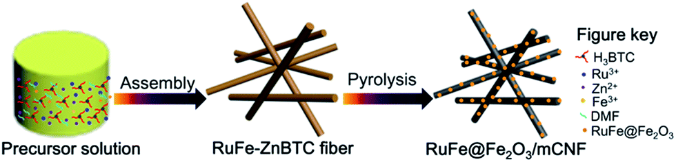
We herein report Ru–Fe alloy mediated α-Fe2O3 particles on mesoporous carbon nanofibers (RuFe@Fe2O3/mCNF) in situ fabricated by skillful construction of Ru, Fe-containing zinc–trimesic acid metal organic framework fibers before pyrolysis. This facile synthesis renders evenly dispersed RuFe@Fe2O3 particles confined into mesoporous CNFs formed simultaneously. The doping of Ru not only contributes to additional pseudocapacitance, but also mediates the dispersion of α-Fe2O3, which presents on the periphery of Ru–Fe alloys. The size of RuFe@Fe2O3 particles is well controlled in the range of 20–33 nm by tailoring the feed ratio of RuCl3 to FeCl3, which also contributes to the variation for porosity and conductivity of final composites. For electrochemical supercapacitor test in 6 M KOH, the elaborately fabricated RuFe@Fe2O3/mCNF-25% (25 at% Ru in total metals) exhibits a large capacitance of 285 F g−1 per mass of the composite electrode, and a high energy density up to 47.6 W h kg−1, as well as good rate capability and outstanding cycling stability. To the best our knowledge, this is the first example to in situ integrate dispersion controlled α-Fe2O3 into mesoporous carbon nanofibers mediated by pseudo-capacitive Ru species. And the integrated merits, such as excellent dispersion, high porosity and conductivity, as well as intimate contact, should be responsible for the superior capacitive performance.
Experimental
Chemicals
Zinc acetate dihydrate (Zn(Ac)2·2H2O, AR), ruthenium chloride (RuCl3, AR), ferric chloride (FeCl3, AR), trimesic acid (C9H6O6, >98%, TCI), N,N-dimethylformamide (DMF, AR), nitrogen (N2, >99.999%), acetylene black (Battery Grade), polytetrafluoroethylene (PTFE, 60 wt%, Aldrich), Ni foam (Battery Grade), and ethanol (AR) are all commercially received and used directly without further purification.Synthesis of RuFe@Fe2O3/mCNF composites
Trimesic acid (H3BTC), RuCl3, FeCl3 and Zn(Ac)2·2H2O were used as precursors for Ru, Fe-containing zinc–trimesic acid metal organic framework fiber synthesis. The molar ratio of precursors used in the preferred preparation is 6H3BTC![[thin space (1/6-em)]](https://www.rsc.org/images/entities/char_2009.gif) :0.0015x RuCl3:0.0015(10 − x) FeCl3:5 Zn(Ac)2·2H2O:650DMF, where x was set to be 3, 5 and 9. Typically, certain amount of metal salts combined with 1.25 g of H3BTC were dissolved in 50 mL of DMF under constant agitation at room temperature for 30 min, and were further solvothermally treated at 140 °C for 12 h. The resulting precipitate was collected after decanting the mother liquor, rinsing with DMF and drying under vacuum, yielding Ru3Fe7–ZnBTC, Ru5Fe5–ZnBTC and Ru9Fe1–ZnBTC fibers. The resulting fibers were then placed in a quartz boat, flushing with N2 flow, and heated in a horizontal tube furnace up to 950 °C at a rate of 5° min−1 and maintained at this temperature for 2 h, yielding RuFe@Fe2O3/mCNF-11%, RuFe@Fe2O3/mCNF-25% and RuFe@Fe2O3/mCNF-40% (Scheme 1).
:0.0015x RuCl3:0.0015(10 − x) FeCl3:5 Zn(Ac)2·2H2O:650DMF, where x was set to be 3, 5 and 9. Typically, certain amount of metal salts combined with 1.25 g of H3BTC were dissolved in 50 mL of DMF under constant agitation at room temperature for 30 min, and were further solvothermally treated at 140 °C for 12 h. The resulting precipitate was collected after decanting the mother liquor, rinsing with DMF and drying under vacuum, yielding Ru3Fe7–ZnBTC, Ru5Fe5–ZnBTC and Ru9Fe1–ZnBTC fibers. The resulting fibers were then placed in a quartz boat, flushing with N2 flow, and heated in a horizontal tube furnace up to 950 °C at a rate of 5° min−1 and maintained at this temperature for 2 h, yielding RuFe@Fe2O3/mCNF-11%, RuFe@Fe2O3/mCNF-25% and RuFe@Fe2O3/mCNF-40% (Scheme 1).
 | ||
| Scheme 1 Schematic description of RuFe@Fe2O3/mCNF composite synthesis. | ||
Characterization
Powder XRD was collected with a Bruker D8 Advance X-ray diffractometer with nickel filtered CuKα radiation (λ = 1.5406 Å). The samples were scanned in the 2θ range from 5 to 80° and in steps of 4° min−1. The infrared spectra of samples were recorded in KBr disks using a Nicolet Nexus 870 FTIR spectrometer. SEM analysis was performed on a FEI-Quanta 200F field-emission scanning microscope operated at 15 kV with an EDX detector to determine the morphology of the prepared samples. The TEM images, high angle annular dark field-scanning TEM (HAADF-STEM) and EDS mapping of elements were analyzed using a FEI Tecnai G2 F20 transmission electron microscope equipped with an energy dispersive X-ray spectroscopic analyzer operated at a voltage of 200 kV. Samples were sonicated for 5 min in EtOH, one drop of the suspended sample was dripped in a holely carbon microgrid supported on a 300 mesh copper grid. N2 adsorption/desorption isotherms were recorded at 77 K using a JW-BK222 static volumetric gas adsorption instrument manufactured by Beijing JWCB Sci. & Tech. Co., Ltd. Before measurements, the samples were de-gassed at 300 °C for 3 h in vacuum. Specific surface area was determined by the Brunauer–Emmett–Teller (BET) method and mesopore size distributions were measured by using Barrett–Joyner–Halenda (BJH) method from the desorption branch of the isotherms. Raman spectra were recorded with a HORIBA JobinYvon HR800 with a microscope attachment. The laser wavelength of 633 nm was focused using a diffraction limited spot, and the scan time was 2 s for each sample. X-ray photoelectron spectroscopy (XPS) was performed on a Thermo ESCALAB 250Xi X-ray photoelectron spectrometer (employing a monochromated Al-Kα) X-ray source (hν = 1486.6 eV). All of the binding energy peaks of XPS spectra were calibrated by placing the principal C1s binding energy peak at 284.8 eV. Peaks from all the high resolution core spectra were fitted with XPSPEAK 4.1 software, using mixed Gaussian–Lorentzian functions. In situ high-energy synchrotron X-ray diffraction measurements were performed on the 11-ID-C beamline of the Advanced Photon Source (APS) at Argonne National Laboratory. X-rays of 115 keV energy and 0.6 mm × 0.6 mm beam size were used to obtain two-dimensional (2D) diffraction patterns in the transmission geometry using a Perkin-Elmer large area detector placed at 1.6 m from the sample. X-ray absorption fine structure (XAFS) was carried out on the 20-BM-B beamline of APS at Argonne National Laboratory. The XAFS data were obtained in the fluorescence mode at the Ru K-edge (22117.0 eV) and Fe K-edge (7112.0 eV) using Ru foil and Fe foil as the reference, respectively. The XAFS data were processed using the Athena software for background removal, post-edge normalization and X-ray absorption near edge structure (XANES) analysis. The oxidation states of the samples were determined by comparing the inflection point of the edge from the sample to that of standards with known oxidation state. The extended X-ray absorption fine structure (EXAFS) was analyzed using Artemis software, which implemented FEFF. The EXAFS data reduction was conducted by utilizing the standard procedures. The EXAFS function, χ, was obtained by subtracting the post-edge background from the overall absorption and then normalized with respect to the edge jump step. Subsequently, k3-weighted χ(k) data in k space were Fourier transformed to r space to separate the EXAFS contributions from the different coordination shells.
Ru and Fe content was estimated by inductively coupled plasma-atomic emission spectroscopy (ICP-AES) analysis conducted on a Perkin Elmer emission spectrometer. Each 10 mg of vacuum-dried RuFe@Fe2O3/mCNF composite was placed in a digester with PTFE lined, and dissolved in 4 mL of aqua Fortis solution mixed with 1 mL H2O2. Microwave digestion was carried out for 20 min to completely dissolve the metal species. After cooling, each solution was filtered through a 0.45 μm polyethersulfone filter and then submitted for analysis.
Electrochemical test
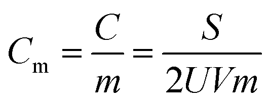
Electrochemical measurements were performed via a conventional three-electrode system in a 6 M KOH-distilled water electrolyte, using a CHI660D electrochemical workstation. The Hg/HgO electrode was used as a reference electrode, and Pt as a counter electrode. The working electrode slurries containing the RuFe@Fe2O3/mCNF synthesized, acetylene black and polytetrafluorethylene at a weight ratio of 7:2:1 were painted on a nickel foam (1 × 1 cm2) to create samples for electrochemical characterization. The coated Ni foam was pressed under a pressure of 3 MPa to enhance the adhesion between the electrode material and the Ni foam. The electrochemical properties were tested by cyclic voltammetry (CV) and galvanostatic charge–discharge (GCD, the potential window in the range of −1.0 to 0 V versus Hg/HgO electrode), and electrochemical impedance spectroscopy (EIS, frequency range between 1 mHz and 103 kHz). The electrochemical capacitance (Cm) of the electrode was determined as follows:in which Cm is the gravimetric specific capacitance (F g−1), C is the capacitance (F), m is the mass of electrode material (g), S is the integrated area of the CV curve, V is the scan rate (mV s−1) and U is the potential window (V).
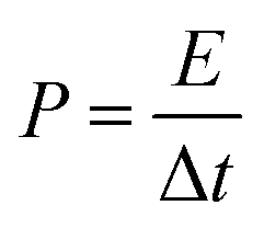
The energy density and power density were estimated, using the following equations:
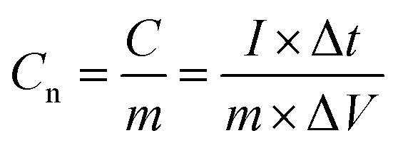

where Cn is the gravimetric specific capacitance (F g−1) based on the galvanostatic charge–discharge test, I is the charge–discharge current (A), ΔV (V) refers to the potential change within the discharge time Δt (s), E (J g−1) refers to the energy density, P (W g−1) corresponds to the average power density.
Results and discussion
Morphological structure and transformation
Fig. 1A shows the typical SEM image of Ru5Fe5–ZnBTC with a Ru/Fe feed ratio of 1.00. It has a fibrous shape with an average diameter of ca. 100 nm and a length of 5–10 μm, implying the successful fabrication of fiber precursors achieved via a self-assembly process. Such fiber precursors bear rich Zn and O species (Fig. S1a†), which constitute the Zn4O secondary building units in Ru, Fe-containing zinc–trimesic acid metal organic frameworks. Stretching vibrations at 1626, 1578, 1374 and 1252 cm−1 demonstrate the presence of phenol-bridged struts,27 as illustrated in the FT-IR pattern of Ru5Fe5–ZnBTC (Fig. S2a†). XPS was undertaken to accurately determine the specific bonding. High-resolution scans of C1s were deconvoluted into three peaks at 284.5, 285.1 and 285.9 eV, along with another peak at 288.7 eV (Fig. 1Ba) for carbon-functional group as C–C, C–N, C–O, and –COOH, respectively.28 The deconvolution of O1s broad peak yields two classic peaks near 531.4 and 532.1 eV (Fig. 1Ca), which are associated with –COOH and C–O groups in Ru5Fe5–ZnBTC.29 Being pyrolyzed at 950 °C, the parent fibrous morphology is inherited in the resulting RuFe@Fe2O3/mCNF-25% (Fig. 1D). The decrease in the Zn content and the absence of stretches from organic struts suggest the evolution of Ru5Fe5–ZnBTC precursor to carbonaceous material (Fig. S1b and S2b†). Correspondingly, three peaks at 284.6, 285.1 and 286.3 eV for C–C, C–N and C–O groups remain in RuFe@Fe2O3/mCNF-25% (Fig. 1Bb), implying the transformation of carboxy-containing struts to inorganic carbons, in accordance with the FT-IR result.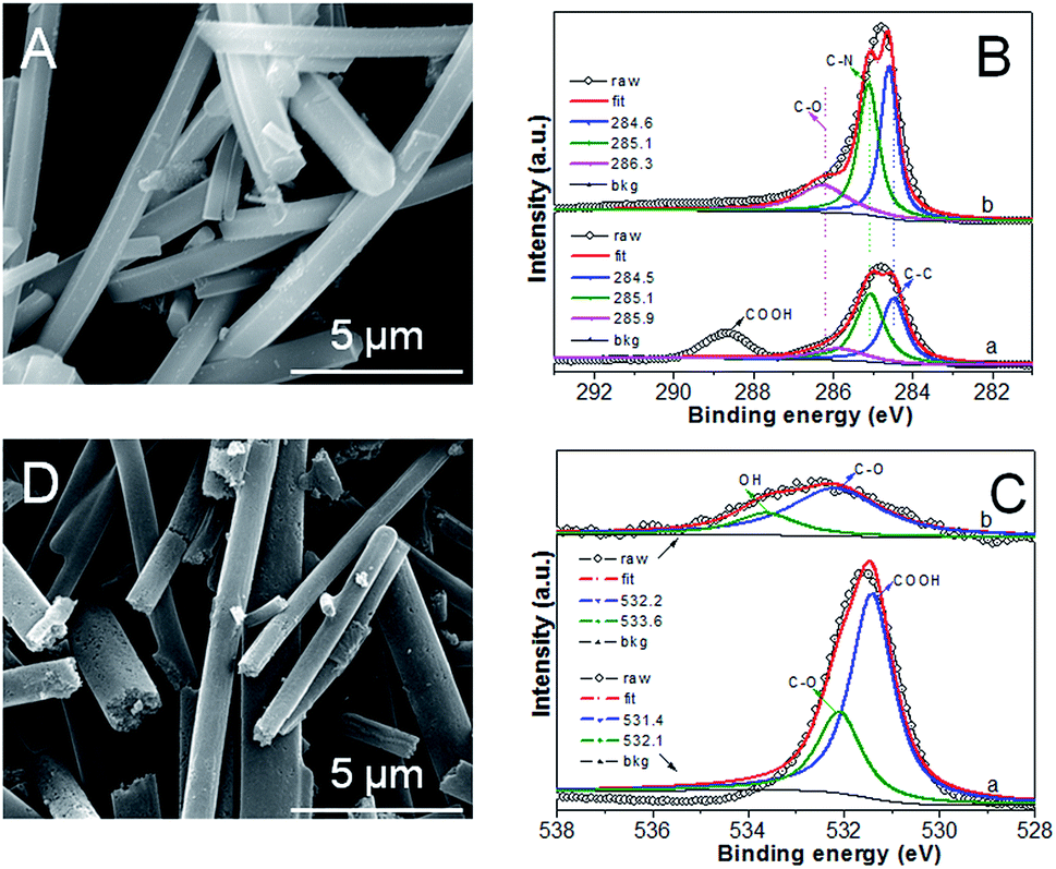 | ||
| Fig. 1 SEM image (A), XPS spectra of C1s (B) for Ru5Fe5–ZnBTC, and XPS spectra of O1s (C), SEM image (D) for RuFe@Fe2O3/mCNF-25%. | ||
X-ray diffraction (XRD) pattern of Ru5Fe5–ZnBTC shows rutile-structured (P42/mnm) diffractions ranging from 5 to 20°,30 which was transformed to (002) and (101) diffractions at 23° and 43°,31 respectively (Fig. 2a). This implies the evolution of crystalline Ru5Fe5–ZnBTC fiber to amorphous carbon. To investigate the local structure of carbon, Raman study of RuFe@Fe2O3/mCNF-25% was performed and the result is shown in Fig. 2b. It is clear that two main peaks present at 1363 and 1607 cm−1, corresponding to the D band and G band of carbons, respectively. In the Raman spectrum, the G band represents the in-plane bond-stretching motion of the pairs of C sp2 atoms (the E2g phonons); whereas the D band corresponds to the breathing mode of rings or k-point phonons of A1g symmetry.32 In addition, a small peak centers around 1511 cm−1, ascribed to the A band from oxygen-functionalized amorphous carbons.33 The presence of O-containing groups is further confirmed in the high-resolution O1s XPS spectrum (Fig. 1Cb). Two main peaks at 532.2 and 533.6 eV are assigned to C–O and OH groups in RuFe@Fe2O3/mCNF-25%.34 The integral area ratio of the “D band” to the G band is 3.4; while the integral area of the “A band” to the “G band” is 0.4, implying that the graphitic structures were not well developed. It is the case that substantial defects are created, which facilitate the confinement of particles within the voids of carbon networks.
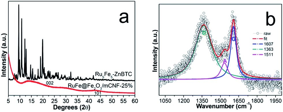 | ||
| Fig. 2 XRD pattern (a), and Raman spectrum (b) of RuFe@Fe2O3/mCNF-25%. | ||
Particle composition and structure
The typical TEM image of RuFe@Fe2O3/mCNF-25% is displayed in Fig. 3a, showing uniform and inter-crossed nanofibers. Investigation of a single nanofiber demonstrates the presence of evenly dispersed particles, as revealed by bright-field TEM and HAADF-STEM images (Fig. 3b and c). Elemental maps show the presence of Fe and Ru elements, which are uniformly distributed throughout a length of nanofiber, along with C, O and residual Zn species (Fig. 3d–i). Mapping a single particle in Fig. 3j reveals its composition, which comprises Fe, Ru and O elements (Fig. 3k–m). These elements are overlapped, demonstrating the atomic mixture of Fe, Ru and O without segregation.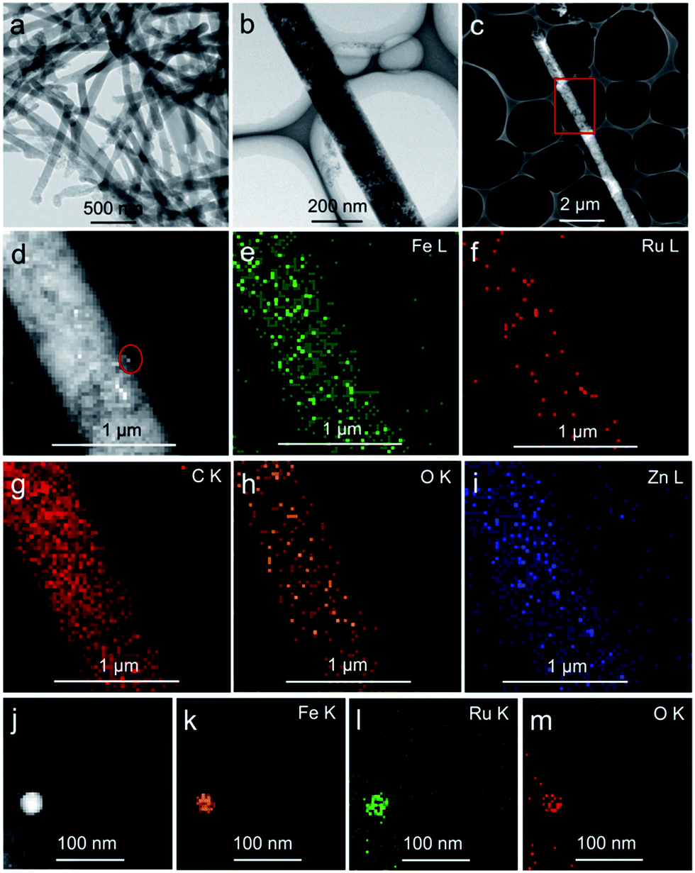 | ||
| Fig. 3 Structure and characteristic of RuFe@Fe2O3/mCNF-25%: (a and b) bright-field TEM image, (c and d) HAADF-STEM image, (e–i) elemental mapping of Fe, Ru, C, O and Zn throughout a single nanofiber, and (j–m) HAADF-STEM image and elemental mapping of Fe, Ru and O of a single particle. | ||
To understand the formation of particles during pyrolysis, in situ high-energy XRD patterns of Ru5Fe5–ZnBTC are collected in Ar atmosphere at increasing temperatures from 30 to 750 °C (Fig. 4). The starting Ru5Fe5–ZnBTC displays a set of rutile-structured diffractions in the 2θ range of 0.5–1.6°. When heated to 300 °C, new diffractions emerge, as represented by the triangle symbols (Fig. 4a), linking to a phase transition. An intensity decrease is observed when heated from 420 to 600 °C, suggesting the decomposition is initially started at 420 °C and completed at ca. 600 °C. Meanwhile, the inorganic carbon forms and is consolidated when further heated. At ca. 660 °C, distinct diffractions of α-Fe2O3 species (JCPDS no. 33-0664) at 2.34°, 3.78°, 4.17°, 4.58° and 4.74° are observed.35 It is worth mentioning that these diffractions slightly shift to lower 2θ angles as compared to those of α-Fe2O3 standard, linking to the expansion of interplanar spacing. It can be inferred that isomorphous replacement of α-Fe2O3 occurred in the presence of Ru(+3). As the temperature was further elevated to 690 °C, diffractions at 3.0°, 5.8°, 6.0° and 7.0° can be clearly identified (Fig. 4b), corresponding to the formation of hcp-structured Ru–Fe alloys (P63/mmc).36 Based on these results, it is probable that the Ru(+3) and Fe(+3) complexes were partially reduced during pyrolysis in the presence of liberated gas (H2, CO, etc.) and carbon. And they are agglomerated to integrated particles including Ru–Fe alloys and substituted α-Fe2O3 through metal–metal and metal–support interactions. However, these species are silent using lab XRD technique probably owing to the low metal dosage. In addition, these diffractions get more intense with increasing temperature to 750 °C, indicating larger crystallite size at higher temperature.
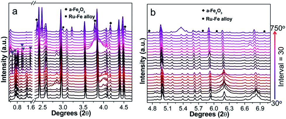 | ||
| Fig. 4 In situ synchrotron high-energy XRD patterns recorded by pyrolysis of Ru5Fe5–ZnBTC in the 2θ range of (a) 0.3–4.7° and (b) 4.7–7.1°. | ||
To acquire the electronic property and local structure of particles, XAFS was measured via a separated Ru K-edge and Fe K-edge scan. As illustrated in Fig. 5A, compared with Ru5Fe5–ZnBTC, RuFe@Fe2O3/mCNF-25% exhibits a negative shift in the adsorption edge position, suggesting the Ru(+3) species are mostly reduced.37,38 Whereas these reduced Ru(+3) species carry some positive charges since the edge position is positively shifted as compared to that of Ru foil.39 In the corresponding k space, RuFe@Fe2O3/mCNF-25% shows clear oscillations at a higher k region of k > 8 Å−1 compared with Ru5Fe5–ZnBTC (Fig. S3†), indicating the dominance of high Z backscatters, which would be Fe or Ru. Consistently, RuFe@Fe2O3/mCNF-25% exhibits one prominent peak at ∼2.2 Å from Ru–Fe contributions, different from ∼1.6 Å from Ru–O pairs in Ru5Fe5–ZnBTC (Fig. 5B), confirming the formation of Ru–Fe alloys.40 As for Fe K-edge analysis, RuFe@Fe2O3/mCNF-25% is similar to Ru5Fe5–ZnBTC in terms of XANES (Fig. 5C), k3-weighted EXAFS (Fig. S4†) and Fourier transformed EXAFS (Fig. 5D). It can be ascribed to the dominance of low Z backscatters around Fe species, which would be O in our system,41 revealing the formation of iron oxides. Curve fitting of EXAFS data in r space for both Ru and/or Fe depending bonds is less satisfactory because the error of coordination number is always larger than 10%. However, the peak intensity is proportional to the coordination number. Interestingly, for RuFe@Fe2O3/mCNF-25%, very strong Ru–Fe and Fe–O contributions are shown in Fig. 5B and D, and relatively weak contributions from Ru–O and Fe–Ru are also observed. This strongly suggests that Ru(+3) species are mostly reduced and interact with a small fraction of reduced Fe species to form Ru–Fe alloys, while most Fe(+3) species retain and prefer to combine with O to form substituted α-Fe2O3.
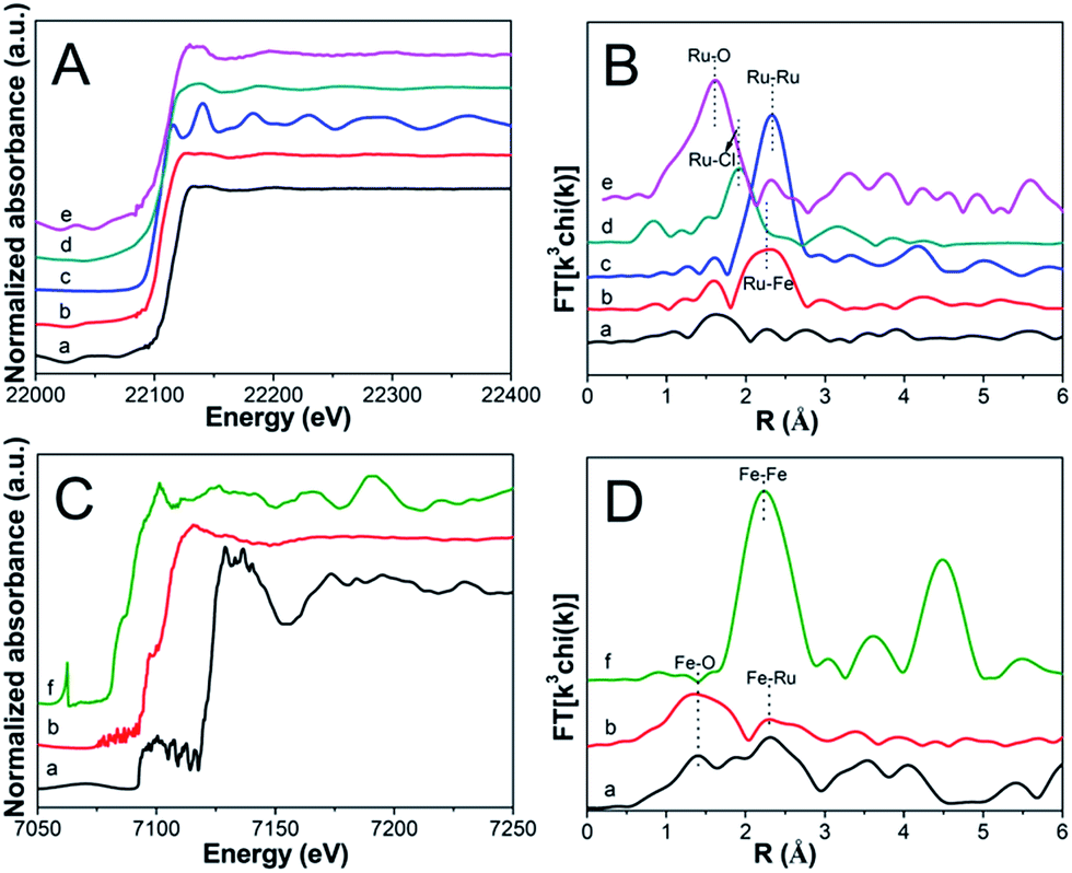 | ||
| Fig. 5 XANES of Ru K-edge (A), EXAFS of Ru K-edge (B), XANES of Fe K-edge (C), and EXAFS of Fe K-edge (D) for (a) Ru5Fe5–ZnBTC, (b) RuFe@Fe2O3/mCNF-25%, (c) Ru foil, (d) RuCl3, (e) RuO2 and (f) Fe foil. | ||
To explore the location and configuration of particles, survey scan using XPS was carried out. As illustrated in Fig. S5,† the survey spectra reveal the presence of C, O, N, Zn, Fe and Ru in Ru5Fe5–ZnBTC, whereas the content of both Fe and Ru is sharply decreased in RuFe@Fe2O3/mCNF-25%, implying that RuFe@Fe2O3 particles are mostly embedded in the carbonaceous network, confirming the TEM result. The detected atomic ratio of Ru to Fe was 0.1, which is smaller than that of 0.3 estimated by ICP-AES. This strongly suggests that α-Fe2O3 components are mostly present on the periphery of Ru–Fe alloys, corresponding to a RuFe@Fe2O3 configuration. Compared to the bare α-Fe2O3 on CNFs, such a configuration renders α-Fe2O3 disperse better. Based on all the above experimental results and analyses, it is clear that one-pot construction of Ru, Fe-containing zinc–trimesic acid fibers was realized and their evolution into Ru–Fe alloy mediated α-Fe2O3 particles (RuFe@Fe2O3) evenly dispersed on carbon nanofibers was achieved in a single step.
Effect of Ru/Fe feed ratio
Doping of Ru improves the dispersion of α-Fe2O3 component, except for its contribution to additional pseudocapacitance. To tailor the property and capacitive performance of final composites, Ru molar percentage was varied by tuning the Ru/Fe feed ratio. In our experiment, the feed ratio of RuCl3 to FeCl3 was set to be 0.43, 1.00 and 9.00. As a result, it is found that the Ru/Fe molar ratio in RuFe@Fe2O3/mCNF composites deviates from that in the synthetic mixture (Table S1†). For example, RuFe@Fe2O3/mCNF-25% is found to have a Ru/Fe molar ratio of 0.34, lower than the feed ratio of 1.00. The estimated Ru/Fe molar ratio increases with the increase of Ru/Fe feed ratio. The higher the Ru/Fe feed ratio, the more is the enrichment of Ru in the composite. The Ru molar percentage in all metals is 11, 25 and 40% in RuFe@Fe2O3/mCNF-11%, RuFe@Fe2O3/mCNF-25% and RuFe@Fe2O3/mCNF-40%, derived from Ru3Fe7–ZnBTC, Ru5Fe5–ZnBTC and Ru9Fe1–ZnBTC, respectively.Accompanied by the change of Ru molar percentage, the evolution of particles was also demonstrated. As shown in Fig. 6, RuFe@Fe2O3/mCNF composites have spherical particles evenly dispersed on the carbonaceous networks, exhibiting a decreased size with Ru molar percentage from 32.9 nm for RuFe@Fe2O3/mCNF-11% to 20.8 nm for RuFe@Fe2O3/mCNF-40%. Interestingly, the more the Ru introduced, the smaller the particle size is. It is known that metallic Ru has a higher melting point, implying that reduced Ru species are less movable than Fe species. As more Ru species are involved, less aggregation occurred during pyrolysis, thereby leading to a smaller size. In this study, the particle size was successfully controlled to be around 23 nm in the case of noble metal saving. This strongly suggests that the dispersion of α-Fe2O3 was enhanced by decreasing the particle size, as well as constructing the RuFe@Fe2O3 configuration.
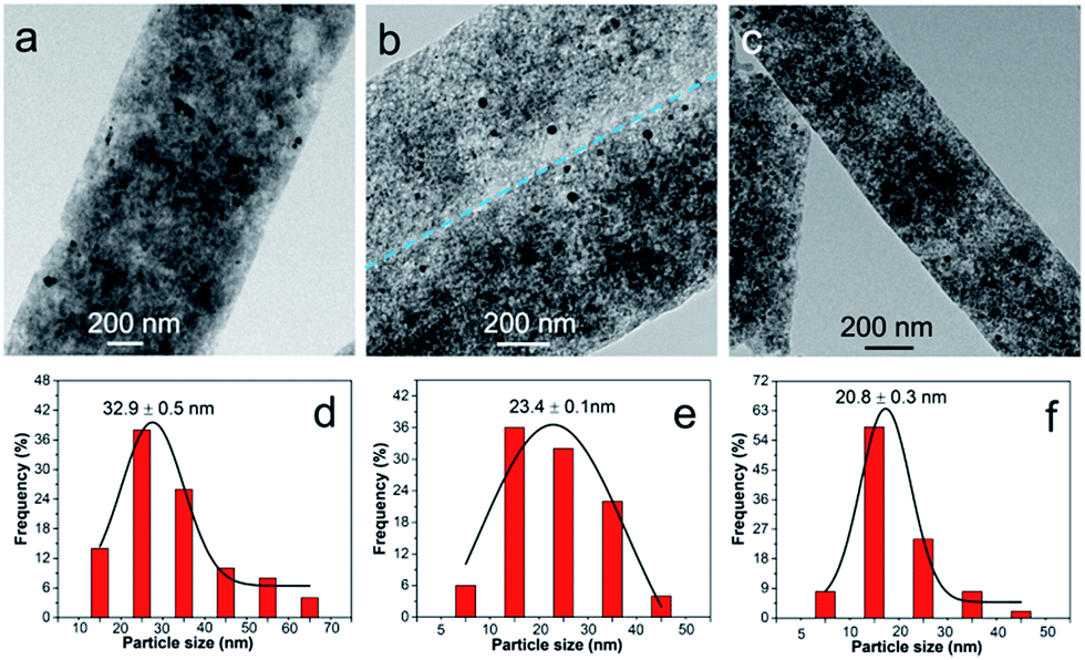 | ||
| Fig. 6 TEM images and the corresponding particle size distribution histograms of (a and d) RuFe@Fe2O3/mCNF-11%, (b and e) RuFe@Fe2O3/mCNF-25% and (c and f) RuFe@Fe2O3/mCNF-40%. | ||
On the other hand, N2 adsorption reveals the pore structure is Ru/Fe molar ratio dependant. The surface area and pore volume vary with the Ru/Fe molar ratio, though all RuFe@Fe2O3/mCNF composites are mesoporous and have a similar pore size ranging from 3.6 to 3.9 nm (Fig. S6†). Increasing Ru/Fe molar ratio leads to an increase first in the surface area and pore volume from 963 m2 g−1 and 1.28 cm3 g−1 for RuFe@Fe2O3/mCNF-11% to 1162 m2 g−1 and 1.30 cm3 g−1 for RuFe@Fe2O3/mCNF-25%, and then a decrease to 919 m2 g−1 and 1.08 cm3 g−1 for RuFe@Fe2O3/mCNF-40% (Table 1). The difference may originate from the interaction between metal species and CNFs.
| Materials | SBETa (m2 g−1) | Vpb (cm3 g−1) | Dpc (nm) | Specific capacitanced (F g−1) |
|---|---|---|---|---|
| a The BET surface area was obtained from the adsorption branches in the relative pressure range of 0.05–0.20.b The single point adsorption total pore volume was taken at the relative pressure of 0.96.c The mesopore size distribution was calculated from the desorption branches by the Barret–Joyner–Halenda (BJH) method.d Calculated based on CV curves at 1 mV s−1. | ||||
| RuFe@Fe2O3/mCNF-11% | 963 | 1.28 | 3.6 | 114 |
| RuFe@Fe2O3/mCNF-25% | 1162 | 1.30 | 3.9 | 285 |
| RuFe@Fe2O3/mCNF-40% | 919 | 1.08 | 3.7 | 180 |
Electrochemical property
To evaluate the electrochemical performance of RuFe@Fe2O3/mCNF composites, cyclic voltammetry (CV) was first performed to investigate the charge storage capacity of composite electrodes. Fig. 7a shows the CV curves of different RuFe@Fe2O3/mCNF composites at a scan rate of 1 mV s−1. All of them exhibit quasi-rectangular and symmetric shapes, suggesting fast reversible faradaic reactions and ideal capacitive behavior. The absence of redox peaks suggests the supercapacitor is charged–discharged at a pseudo-constant rate over the complete voltammetric cycle.42 The specific capacitance is proportional to the integrated CV area. RuFe@Fe2O3/mCNF-25% exhibits a larger specific capacitance of 285 F g−1; while RuFe@Fe2O3/mCNF-11% and RuFe@Fe2O3/mCNF-40% have a smaller specific capacitance of 114 and 180 F g−1, respectively. It is clear that the capacitance is Ru molar percentage relevant. On the other hand, increasing the total metal content from 7.15 to 16.58 mmol g−1, the capacitance jumps to as high as 285 F g−1 for RuFe@Fe2O3/mCNF-25%, and drops to 114 F g−1 for RuFe@Fe2O3/mCNF-11% (Tables 1 and S1†). This suggests that excessive loading of redox species would deteriorate the capacitive behavior of electrodes. As mentioned by Huang and coworkers, the densely anchored metal oxides would surely block the diffusion pathway of ions and electrolyte for energy storage, thus leading to lower specific capacitance.43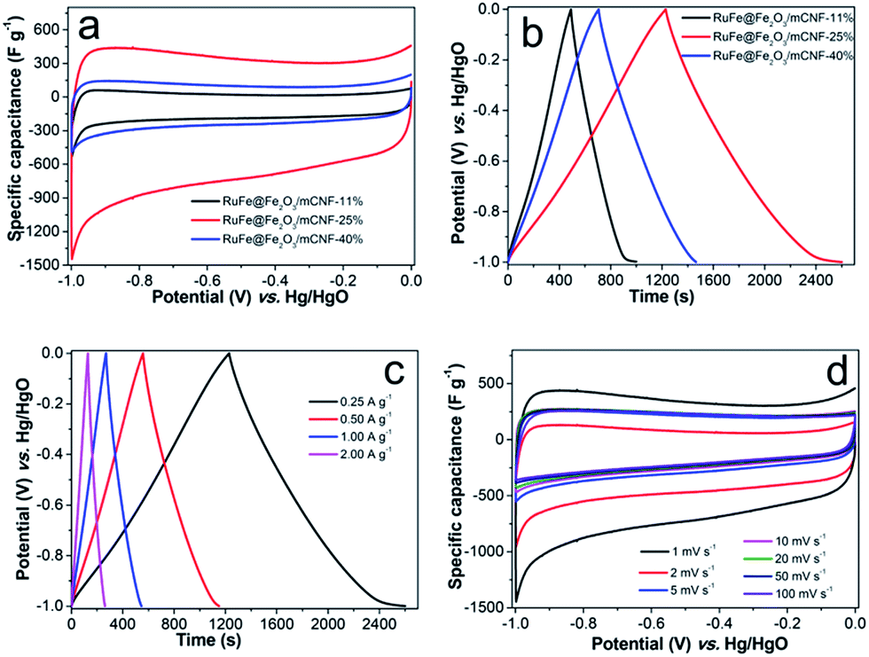 | ||
| Fig. 7 Capacitive performance: (a) CV curves at 1 mV s−1, (b) GCD curves at 0.25 A g−1, (c) charge–discharge curves of RuFe@Fe2O3/mCNF-25% at various current densities and (d) CV curves at different scans for RuFe@Fe2O3/mCNF-25%. | ||
Fig. 7b presents the charge–discharge curves at a current density of 0.25 A g−1. Charge–discharge curves of RuFe@Fe2O3/mCNF electrodes are highly linear and symmetrical, indicating excellent electrochemical reversibility and charge–discharge efficiency (nearly 100%). RuFe@Fe2O3/mCNF-25% has a significantly higher charge storage capacity than other electrode materials, showing a 7–57% increase in the discharge time. The change of capacitance based on the GCD curves (Table S2†) is consistent with that from the cyclic voltammograms. RuFe@Fe2O3/mCNF-25% shows an impressive rate capability. A good symmetry and fairly linear slopes are observed in the GCD curves at current densities of 0.25–2.00 A g−1 (Fig. 7c), indicating a good electrochemical capacitive characteristic and superior reversible redox reaction. It reveals a good rate performance, especially at large charge–discharge current densities, implying that RuFe@Fe2O3/mCNF-25% is suitable for application in supercapacitors in which the rapid charge–discharge is required. Additionally, the voltage loss is low even at a high current density, indicating a low internal resistance.
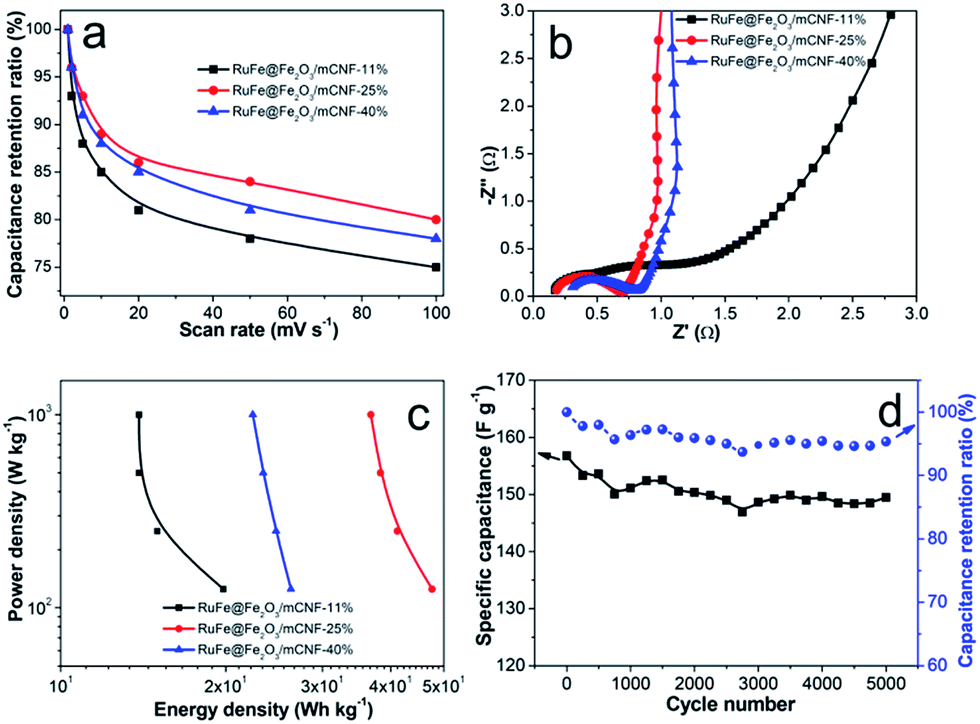
The superior RuFe@Fe2O3/mCNF-25% was then subjected to further CV investigation under different scan rates (Fig. 7d). The CV curves retain a relatively rectangular shape without a very oblique angle even at a scan rate as high as 100 mV s−1, indicating the highly capacitive nature with rapid charging–discharging characteristics.44 The specific capacitance decreases by 23% (from 285 to 147 F g−1) as the sweep rate increases from 1 to 100 mV s−1, indicating the excellent mesoporosity.45 RuFe@Fe2O3/mCNF-25% has a large surface area and pore volume. These properties have allowed a high rate of solution infiltration and facilitate the ion insertion/extraction and electron transportation. The relationship between the capacitance retention ratio and potential scan rate is plotted (Fig. 8a). The minimized capacitance at a high scan rate originates from the decreased ion accessible surface areas. The higher the capacitance retention ratio is, the better the ion transport behavior will be. The capacitance retention ratios at 100 mV s−1 are all above 75% for RuFe@Fe2O3/mCNF composites, suggesting the superior porosity.
 | ||
| Fig. 8 (a) Capacitance retention ratios as a function of scan rates in 6 M KOH, (b) Nyquist plots, (c) Ragone plots, and (d) cycling stability of RuFe@Fe2O3/mCNF-25%. | ||
The EIS analysis is a powerful and informative technique to evaluate the properties of conductivity and charge transport in the electrode/electrolyte interface. The equivalent circuit fitting of the Nyquist plot of RuFe@Fe2O3/mCNF-25% is shown in Fig. S7.† The semicircular part in the higher frequency corresponds to the charge transfer at the electrode/electrolyte interface, and its diameter is equivalent to the faradaic charge transfer resistance (Rct). Solution resistance (Rs) is the intersection of the curve at real part Z′. It is a combinational resistance of ionic resistance of electrolyte, intrinsic resistance of substrate, and contact resistance between electrode and current collector. The slope of the curves at a low frequency is called Warburg impedance (W), which is induced by ion diffusion/transport from the electrolyte to the electrode surface. Comparing the Nyquist plots of different composites (Fig. 8b), it is found that both RuFe@Fe2O3/mCNF-25% and RuFe@Fe2O3/mCNF-40% show a nearly vertical line in the low frequency region, exhibiting excellent capacitor behavior. The Rs is estimated to be 0.17, 0.18 and 0.31 Ω for RuFe@Fe2O3/mCNF-11%, RuFe@Fe2O3/mCNF-25% and RuFe@Fe2O3/mCNF-40%, respectively, suggesting the influence of Ru molar percentage on the conductivity. Moreover, RuFe@Fe2O3/mCNF-25% shows a smaller Rct compared with other two, confirming the superior conductivity.
The power density and energy density are two important parameters for evaluating the electrochemical performance of supercapacitors. Fig. 8c presents the Ragone plots of RuFe@Fe2O3/mCNF electrodes. The highest energy is obtained from RuFe@Fe2O3/mCNF-25%, which is 47.6 W h kg−1 at the power density of 125 W kg−1. This demonstrates the potential application of RuFe@Fe2O3/mCNF-25% in efficient and flexible energy-storage devices.
Since long cycle life is very important to electrochemical capacitors, the stability of RuFe@Fe2O3/mCNF-25% in the electrolyte was tested using the galvanostatic charge–discharge at a current density of 10 A g−1. The specific capacitance of RuFe@Fe2O3/mCNF-25% remains almost constant with a slight fluctuation, and 95.3% of the original capacitance is retained when cycling up to 5000 cycles, as demonstrated in Fig. 8d. The fading rate is only 0.01‰ per cycle, which makes RuFe@Fe2O3/mCNF-25% highly stable during the repeated charge–discharge process. Such a high stability can be ascribed to the tight contact between RuFe@Fe2O3 particle and carbon nanofiber rendered by the in situ synthesis. The cycling performance of RuFe@Fe2O3/mCNF-25% is much better than that of FeNi alloy particle-decorated graphene prepared by a stepwise procedure (ca. 3.6% loss after 1000 cycles).46
Conclusions
In summary, Ru–Fe alloy mediated α-Fe2O3 particles on mesoporous carbon nanofibers were successfully developed by construction and evolution of Ru, Fe-containing zinc–trimesic acid metal organic framework fibers. The resulting RuFe@Fe2O3 particles are evenly embedded into the mesoporous carbon nanofibers formed simultaneously, and prove to be substituted α-Fe2O3 present on the periphery of Ru–Fe alloys. Particle size, as well as composite porosity and conductivity are varied with the Ru/Fe feed ratio. The elaborately fabricated RuFe@Fe2O3/mCNF-25% displays a large capacitance and energy density, and good rate capability and outstanding cycling stability, as well as application potential for supercapacitors. The integrated merits, such as excellent dispersion, high porosity and conductivity, as well as intimate contact, should be responsible for the superior capacitive performance.Acknowledgements
The authors gratefully acknowledge financial support from the National Natural Science Foundation of China (21303229, 51471187, 51571211), Beijing Natural Science Foundation (2152025, 2152026), and Science Foundation of China University of Petroleum, Beijing (2462013YJRC018). Sector 20 facilities at the Advanced Photon Source, and research at these facilities, are supported by the US Department of Energy-Basic Energy Sciences, the Canadian Light Source and its funding partners, the University of Washington, and the Advanced Photon Source. Use of the Advanced Photon Source, an Office of Science User Facility operated for the U.S. Department of Energy (DOE) Office of Science by Argonne National Laboratory, supported by the U.S. DOE under Contract No. DE-AC02-06CH11357, is also acknowledged.Notes and references
- G. P. Wang, L. Zhang and J. J. Zhang, Chem. Soc. Rev., 2012, 41, 797–828 RSC.
- M. J. Zhi, C. C. Xiang, J. T. Li, M. Li and N. Q. Wu, Nanoscale, 2013, 5, 72–88 RSC.
- J. Tang and Y. Yamauchi, Nat. Chem., 2016, 8, 638–639 CrossRef CAS PubMed.
- R. R. Salunkhe, C. Young, J. Tang, T. Takei, Y. Ide, N. Kobayashia and Y. Yamauchi, Chem. Commun., 2016, 52, 4764–4767 RSC.
- N. L. Torad, R. R. Salunkhe, Y. Q. Li, H. Hamoudi, M. Imura, Y. Sakka, C.-C. Hu and Y. Yamauchi, Chem.–Eur. J., 2014, 20, 7895–7900 CrossRef CAS PubMed.
- M. X. Liu, L. H. Gan, W. Xiong, Z. J. Xu, D. Z. Zhu and L. W. Chen, J. Mater. Chem. A, 2014, 2, 2555–2562 CAS.
- S. Chen, W. Xing, J. J. Duan, X. J. Hu and S. Z. Qiao, J. Mater. Chem. A, 2013, 1, 2941–2954 CAS.
- M. S. Kolathodi, M. Palei and T. S. Natarajan, J. Mater. Chem. A, 2015, 3, 7513–7522 CAS.
- B. Wang, J. S. Chen, Z. Y. Wang, S. Madhavi and X. W. Lou, Adv. Energy Mater., 2012, 2, 1188–1192 CrossRef CAS.
- S. K. Meher, P. Justin and G. R. Rao, ACS Appl. Mater. Interfaces, 2011, 3, 2063–2073 CAS.
- S. Wu, W. Chen and L. Yan, J. Mater. Chem. A, 2014, 2, 2765–2772 CAS.
- A. Ghosh, E. J. Ra, M. H. Jin, H. Jeong, T. H. Kim, C. Biswas and Y. H. Lee, Adv. Funct. Mater., 2011, 21, 2541–2547 CrossRef CAS.
- B. P. Bastakoti, H. Oveisi, C.-C. Hu, K. C. W. Wu, N. Suzuki, K. Takai, Y. Kamachi, M. Imura and Y. Yamauchi, Eur. J. Inorg. Chem., 2013, 2013, 1109–1112 CrossRef CAS.
- D. W. Wang, Q. H. Wang and T. M. Wang, Nanotechnology, 2011, 22, 135604 CrossRef PubMed.
- K. Y. Xie, J. Li, Y. Q. Lai, W. Lu, Z. A. Zhang, Y. X. Liu, L. M. Zhou and H. T. Huang, Electrochem. Commun., 2011, 13, 657–660 CrossRef CAS.
- X. Zhao, C. Johnston and P. S. Grant, J. Mater. Chem., 2009, 19, 8755–8760 RSC.
- Z. L. Ma, X. B. Huang, S. Dou, J. H. Wu and S. Y. Wang, J. Phys. Chem. C, 2014, 118, 17231–17239 CAS.
- H. Jiang, L. P. Yang, C. Z. Li, C. Y. Yan, P. S. Lee and J. Ma, Energy Environ. Sci., 2011, 4, 1813–1819 CAS.
- G.-H. An and H.-J. Ahn, J. Power Sources, 2014, 272, 828–836 CrossRef CAS.
- L. Yang, S. Cheng, Y. Ding, X. B. Zhu, Z. L. Wang and M. L. Liu, Nano Lett., 2012, 12, 321–325 CrossRef CAS PubMed.
- X. W. Liu, D. H. Teng, T. Li, Y. H. Yu, X. H. Shao and X. P. Yang, J. Power Sources, 2014, 272, 614–621 CrossRef CAS.
- B. Wang, J. L. Cheng, Y. P. Wu, D. Wang and D. N. He, J. Mater. Chem. A, 2013, 1, 1368–1373 CAS.
- Y. M. Chen, X. Y. Li, X. Y. Zhou, H. M. Yao, H. T. Huang, Y.-W. Mai and L. M. Zhou, Energy Environ. Sci., 2014, 7, 2689–2696 CAS.
- Y. Dong, H. M. Lin, Q. M. Jin, L. Li, D. Wang, D. Zhou and F. Y. Qu, J. Mater. Chem. A, 2013, 1, 7391–7398 CAS.
- H. Q. Wang, C. F. Zhang, Z. X. Chen, H. K. Liu and Z. P. Guo, Carbon, 2015, 81, 782–787 CrossRef CAS.
- M.-S. Wang, W.-L. Song, J. Wang and L.-Z. Fan, Carbon, 2015, 82, 337–345 CrossRef CAS.
- M. R. Maurya, A. K. Chandrakar and S. Chand, J. Mol. Catal. A: Chem., 2007, 270, 225–235 CrossRef CAS.
- T. C. Nagaiah, A. Bordoloi, M. D. Sánchez, M. Muhler and W. Schuhmann, ChemSusChem, 2012, 5, 637–641 CrossRef CAS PubMed.
- Y. Lei, J. Li, Y. Y. Wang, L. Gu, Y. F. Chang, H. Y. Yuan and D. Xiao, ACS Appl. Mater. Interfaces, 2014, 6, 1773–1780 CAS.
- L. H. Xie, S. X. Liu, B. Gao, C. D. Zhang, C. Y. Sun, D. H. Li and Z. M. Su, Chem. Commun., 2005, 2402–2404 RSC.
- J. Jiang, J. H. Zhu, W. Ai, Z. X. Fan, X. N. Shen, C. J. Zou, J. P. Liu, H. Zhang and T. Yu, Energy Environ. Sci., 2014, 7, 2670–2679 CAS.
- J. Yan, Z. J. Fan, W. Sun, G. Q. Ning, T. Wei, Q. Zhang, R. F. Zhang, L. J. Zhi and F. Wei, Adv. Funct. Mater., 2012, 22, 2632–2641 CrossRef CAS.
- L. C. Ma, L. H. Meng, Y. W. Wang, G. S. Wu, D. P. Fan, J. L. Yu, M. W. Qi and Y. D. Huang, RSC Adv., 2014, 4, 39156–39166 RSC.
- Z. F. Zhou, Z. H. Zhang, H. R. Peng, Y. Qin, G. C. Li and K. Z. Chen, RSC Adv., 2014, 4, 5524–5530 RSC.
- X. Zhao, C. Johnston and P. S. Grant, J. Mater. Chem., 2009, 19, 8755–8760 RSC.
- L. Y. Liu, J.-W. Lee and B. N. Popov, J. Power Sources, 2006, 162, 1099–1103 CrossRef CAS.
- L. S. Sarma, C.-H. Chen, S. M. S. Kumar, G.-R. Wang, S.-C. Yen, D.-G. Liu, H.-S. Sheu, K.-L. Yu, M.-T. Tang, J.-F. Lee, C. Bock, K.-H. Chen and B.-J. Hwang, Langmuir, 2007, 23, 5802–5809 CrossRef CAS PubMed.
- B. J. Hwang, C.-H. Chen, L. S. Sarma, J.-M. Chen, G.-R. Wang, M.-T. Tang, D.-G. Liu and J.-F. Lee, J. Phys. Chem. B, 2006, 110, 6475–6482 CrossRef CAS PubMed.
- S. H. Sun, G. X. Zhang, N. Gauquelin, N. Chen, J. G. Zhou, S. L. Yang, W. F. Chen, X. B. Meng, D. S. Geng, M. N. Banis, R. Y. Li, S. Y. Ye, S. Knights, G. A. Botton, T.-K. Sham and X. L. Sun, Sci. Rep., 2013, 3, 1775, DOI:10.1038/srep017751.
- K. R. Kannan, G. U. Kulkarni and C. N. R. Rao, Catal. Lett., 1992, 14, 149–163 CrossRef CAS.
- B. T. Qiao, A. Q. Wang, X. F. Yang, L. F. Allard, Z. Jiang, Y. T. Cui, J. Y. Liu, J. Li and T. Zhang, Nat. Chem., 2011, 3, 634–641 CrossRef CAS PubMed.
- M. X. Liu, L. H. Gan, W. Xiong, Z. J. Xu, D. Z. Zhu and L. W. Chen, J. Mater. Chem. A, 2014, 2, 2555–2562 CAS.
- Y. P. Huang, Y.-E. Miao, W. W. Tjiu and T. X. Liu, RSC Adv., 2015, 5, 18952–18959 RSC.
- Y. M. Tan, C. F. Xu, G. X. Chen, Z. H. Liu, M. Ma, Q. J. Xie, N. F. Zheng and S. Z. Yao, ACS Appl. Mater. Interfaces, 2013, 5, 2241–2248 CAS.
- H.-L. Jiang, B. Liu, Y.-Q. Lan, K. Kuratani, T. Akita, H. Shioyama, F. Q. Zong and Q. Xu, J. Am. Chem. Soc., 2011, 133, 11854–11857 CrossRef CAS PubMed.
- A. G. El-Deen, M. El-Newehy, C. S. Kim and N. A. M. Barakat, Nanoscale Res. Lett., 2015, 10, 1–7 CrossRef CAS PubMed.
Footnote |
| † Electronic supplementary information (ESI) available. See DOI: 10.1039/c6ra27324f |
| This journal is © The Royal Society of Chemistry 2017 |