 Open Access Article
Creative Commons Attribution 3.0 Unported Licence
Electrodeposition of aluminium foils on carbon electrodes in low temperature ionic liquid†
Xianneng Tuab,
Junling Zhangb,
Meng Zhang *a,
Yingjun Caib,
Haiyan Langb,
Guoxin Tiana and
Yanli Wanga
aHarbin Engineering University, Harbin 150001, P. R. China. E-mail: happymeng1980@hrbeu.edu.cn
bBeijing Key Laboratory of Ionic Liquids Clean Process, Key Laboratory of Green Process and Engineering, Institute of Process Engineering, Chinese Academy of Sciences, Beijing 100190, P. R. China
First published on 7th March 2017
Abstract
To inhibit dendrite formation for aluminium electrodeposition in room-temperature ionic liquid electrolyte, a promising method for electrodeposition of non-dendritic aluminium foils on carbon cathodes is investigated. The effect of current density, deposition time, temperature, and cathode materials on the deposit morphology of aluminium foils in AlCl3–1-butyl-3-methyl-imidazolium chloride (AlCl3–[Bmim]Cl) ionic liquid electrolyte was also studied. The prepared aluminium foils are compact, bright and easy to peel off from the carbon electrodes after electrodeposition. The experimental results show that the high current density and low electrowinning temperature is responsible for the compactness of aluminium foils. The intensity of the (200) plane enhances with the increase of current density. Cathodic current efficiencies of the electrodeposition process are from 79% to 87%. The mechanisms of electrodeposition of non-dendritic aluminium foils in ionic liquids are proposed.
1. Introduction
Aluminium is lightweight and has excellent corrosion resistance and electric conductivity and is thus a promising material for various applications. The conventional industrial aluminium electrowinning process such as the Hall–Heroult1 process uses a high temperature of 800 °C to 950 °C, consumes high energy (15 to 18 kW h kg−1 aluminum), and generates pollution gases such as CO, CO2, CF4, fluorides, etc.2 Ionic liquids (ILs) are widely studied in aluminium electrolysis due to their unique chemical and physical properties. It has advantages of low energy consumption (9.1 kW h kg−1 aluminum), low operating temperatures (≤100 °C), no emission of pollutants, and no gases are evolved during the electrolysis, as compared with the conventional industrial aluminum electrowinning processes. Electrodeposition of aluminium in low temperature ionic liquid process shows a good application prospect for aluminium electrowinning and electrofining.3,4Cathode materials have effect the interaction energy of the electrodeposited adatoms with substrate in the low temperature electrolysis process.5,6 Strong interaction energy of deposit adatoms is in favor of yielding aluminium in the case of electroplating aluminium with excellent adhesion to the substrates. Most of the previous studies concerning the electrodeposition of aluminium mainly focused on aluminium electroplate on metal substrates from room-temperature ionic liquids, such as stainless steel,7 tungsten,8–10 copper,11–13 which could get compact and adherent deposits. The electrodeposition of aluminium on aluminium substrate mainly was studied in recycling and refining of aluminum.10,14–16 But dendritic deposition, which was commonly observed in recycling and refining electrodeposition, hinders the production process. Phenomena of ramified electrochemical growth has been studied.17,18 The depletion of ions generates anisotropy surface kinetics and local electric fields near the cathode which readily leads to the dendrite at the edge of deposits. The dendritic arm causes short circuits between anodes and cathodes, which leads to production shutdown and reduces efficiency of the process. Hence, the dendritic aluminium electrodeposit is one of major problem concerning low temperature aluminium electrowinning process. Wiechmann et al.19 estimated that the elimination of short circuiting can improve earning up to 15% because of increasing current efficiency, current density, and production in the copper electrorefining process. Reddy and coworkers14,15 reported electrowinning and electrorefining of aluminium used modified aluminium cathode to eliminate dendritic aluminium electrodeposit.
However, the electrodeposition of aluminium on non-metal substrates (such as glassy carbon or graphite) in ionic liquid are seldom reported. Osteryoung20 reported the electrochemical behavior of aluminium on GC electrode in AlCl3–ionic liquids, but did not obtain the product and the morphology of aluminium particles.
To the best of our knowledge, the electrodeposition of aluminium foils on the metal or nonmetal substrates in a low temperature AlCl3–[Bmim]Cl bath has not previously been explored. Herein, we developed a novel method that makes aluminium foils large, compact and easily peel off from substrate. The electrodeposition of aluminium foils from AlCl3–[Bmim]Cl with a molar ratio of 2![[thin space (1/6-em)]](https://www.rsc.org/images/entities/char_2009.gif) :
:![[thin space (1/6-em)]](https://www.rsc.org/images/entities/char_2009.gif) 1 on the carbon cathode was investigated. And the mechanisms of electrodeposition of non-dendritic aluminium foils are also proposed.
1 on the carbon cathode was investigated. And the mechanisms of electrodeposition of non-dendritic aluminium foils are also proposed.
2. Experimental
2.1 Materials and chemicals
[Bmim]Cl was purchased from LinZhuo Tech. En. Co., anhydrous AlCl3 was purchased from Sinopharm Chemical Reagent Co. (AlCl3, >99%) was used without further purification. All the chemicals used in this work were purchased commercially with analytic grade and used as received.2.2 Preparation and characterization of [Bmim]Cl–AlCl3
[Bmim]Cl was dried for 48 h under vacuum at 100 °C to remove water. The final product was obtained as a white wax-like solid at room temperature. AlCl3 crystals were mixed with [Bmim]Cl in a molar ratio of 2![[thin space (1/6-em)]](https://www.rsc.org/images/entities/char_2009.gif) :
:![[thin space (1/6-em)]](https://www.rsc.org/images/entities/char_2009.gif) 1 yielding a dark yellow liquid, and then were pre-electrolyzed by aluminium plates as electrodes for 48 h to remove residual water and foreign material ion yielding a colorless liquid. And experiments were carried out in an argon-filled glove box (MIKROUNA Universal, O2 below 1 ppm, H2O below 1 ppm). The temperature of the sample was maintained to ±0.1 K via a builtin precise Peltier thermostat.
1 yielding a dark yellow liquid, and then were pre-electrolyzed by aluminium plates as electrodes for 48 h to remove residual water and foreign material ion yielding a colorless liquid. And experiments were carried out in an argon-filled glove box (MIKROUNA Universal, O2 below 1 ppm, H2O below 1 ppm). The temperature of the sample was maintained to ±0.1 K via a builtin precise Peltier thermostat.
2.3 Electrodeposition of aluminium foils
The experiments were carried out with a three-electrode system (Fig. S1a†). The working electrodes were glassy carbon (GC, Aida, 3 mm diameter) or graphite (Aida, 10 mm diameter), the counter electrode was glassy carbon (20 mm × 20 mm × 1 mm), pure aluminium wire (1 mm diameter, 99.9% pure, Alfa Aesar) coated by a heat shrink tube was used as reference electrode. The electrodes were first polished to a nearly mirror finish with an aqueous slurry of 0.05 μm alumina. Thereafter, they were rinsed with ultrapure water and ultrasonically cleaned in ethanol for 5 min and finally dried with cold N2 flow.Experiments were performed with an electrochemical workstation (AutoLab) controlled by Nova 1.2 software in a three-electrode cell. The electrolyte was stirred at a constant speed using a magnetic stirrer. The temperature was controlled by a digital hot plate (IKA, C-MAG, HS-7), and a thermometer was inserted into the electrolyte to monitor the temperature. After the electrolysis, deposit was carefully cleaned several times with CH2Cl2 and drying and weighting before observed.
2.4 Material characterizations
Bulk powder X-ray diffractograms were collected with Empyrean, PANalytical B. V. equipped with a Cu Kα source (λ = 1.5406 Å). Scanning electron micrographs were taken at 5 kV with a Hitachi SU8020 SEM equipped with an SE/BSE detector. Energy dispersive spectra (EDS) were taken at 20 kV.3. Results and discussion
3.1 Effect of current density on deposition layer
To evaluate the morphology of aluminium deposits under different current density on GC electrode, chronopotentiometry study is adopted. Fig. 1 shows the surface morphology of the aluminium deposits under different current density. Under the same applied electric charge, the deposited particles become coarser at low current density (16 mA cm−2). Meanwhile, deposited particles grow together and agglomerate rather than separated particles. However, with further increase of current density, the grain size of the deposits decreases. | ||
| Fig. 1 SEM images of aluminium foil under different current density and same applied electric charge deposition (a) 16 mA cm−2, 2 h (b) 32 mA cm−2, 1 h (c) 57 mA cm−2, 0.55 h (temperature = 50 °C). | ||
At the low current density, the discharge of ions at the cathode is low, so the growth rate of nuclei will be higher than the rate of new nuclei formation; as a result, the deposits become coarse.21 However, as current density increased, the deposited particles become fine-grained,22 which can be attributed to the faster formation rate of new nucleus as compared with the growth rate of that. It is also observed that the high current density (32 and 57 mA cm−2) leads to a uniform deposition, and the surface becomes relatively smooth. Ionic liquids decompose when the potential larger than their equilibrium potential at 57 mA cm−2 are applied.
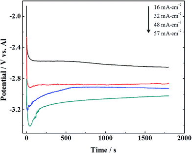
Fig. 2 shows the variation of potential with time at different current density on GC electrode at 50 °C. It is clear that the cathodic potential becomes negative with an increase of current density. An increase in current density can result in a higher overpotential which causes a rising nucleation rate. During electrodeposition the higher rate of nucleation is, the finer grain of the deposits is.23 It is evident that the grain size of the deposits decreases with increasing current density from 16 to 57 mA cm−2, which is consistent with our SEM image (Fig. 1) and the previous report.24 There are overpotential electrodeposition on glassy carbon at various current densities, indicating a weak interaction energy of aluminium atoms with the GC substrate.5 It is easy to peel off aluminium foils from GC substrate after electrodeposition due to this weak interaction energy. The photography of aluminium foils on GC electrode after deposition is shown in Fig. S1c.†
Fig. 3 shows the images of aluminium foils at different time intervals with a current density 57 mA cm−2, 50 °C (all deposits are compact). Fig. 3a and b show the SEM images of aluminium foils which are deposited for 0.5 h and 1 h, respectively. It can clearly be seen that the surfaces of aluminium foils are compact and homogeneous, and aluminium particles are granular and isolated. With increasing the time interval (Fig. 3c and d) the aluminium foils become clustering and dendritic. The SEM results show that 1 h can be the transition deposit time interval which result in the morphology changes from granular to agglomeration at current density of 57 mA cm−2.
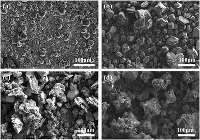 | ||
| Fig. 3 SEM images of the aluminium foils at different time intervals (a) 0.5 h (b) 1 h (c) 2 h (d) 4 h (current density = 57 mA cm−2, temperature = 50 °C). | ||
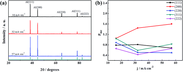
The XRD patterns of electrodeposits at varies current density with same applied electric charge are shown in Fig. 4a. The XRD patterns of all the samples match well with the standard values for aluminium in JCPDS cards no. 01-089-2769. It shows only the diffraction peaks of aluminium. The EDS results also confirm that the deposit is only composed of aluminium in Fig. S2.†
The normalized integrated intensity, Phkl, for the (111), (200), (220), (311), and (222) reflections were calculated by literatures.13,25,26 The calculated crystallographic orientations of electrodeposits obtain with different current densities are plotted in Fig. 4b. It is obviously observed from the crystallographic orientation that the intensity of the (200) plane increase and the intensity of the (111) plane decrease with increasing current density. These results show that current density has significant influence on the crystallographic orientation.
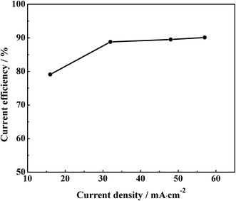
Fig. 5 shows the variation of current efficiency as a function of applied current density at temperature 50 °C. The results show that the current efficiency is from 79.1% to 89.5% as the current density increases from 16 to 57 mA cm−2. The aluminium foils have weight loss in the cleaning process. The more dendrites of aluminum foils have, the larger of aluminium foils' weight lose. The clustering and dendritic aluminium foils have a pretty large weight loss in the cleaning process at low current density. So, the current efficiency is indirectly responsible for the compact degrees of aluminium foils. The aluminium foils become compact with the increase of current density.
3.2 Effect of temperature on deposition layer
The deposit morphologies at different temperatures are shown in SEM images (Fig. 6). As shown in Fig. 6, the shapes of particles are uniform at 40 °C and 50 °C and at 60 °C is irregular. However, a powdery bulk aggregation is found at 70 °C, which formed non-compact foil on GC cathode surface (no pictures). At the low temperature, the aluminium foils seem to be smooth, compact and uniform. The thermal motion of deposit molecules is drastic with increased temperature, the arrangement of deposit molecules becomes disorder at high temperature. Hence, the particle sizes of aluminium deposit increase and the particle shapes of aluminium become more irregular with increasing of temperature. | ||
| Fig. 6 SEM images of aluminium foils at different temperature (a) 40 °C (b) 50 °C (c) 60 °C (current density = 32 mA cm−2, deposition time = 1 h). | ||
Fig. 7 shows the variation of current efficiencies and thickness of aluminium foils at different temperature with 32 mA cm−2 and deposit time of 1 h. The deposit thickness increases when temperature increases. Because the particles are irregular and the grain sizes increase at high temperature. The decrease in current efficiency at high temperatures may be due to two reasons. First, when the temperature of the electrolytes increases, the rate of oxidized species (Cl−) dispersing and formed Cl2 dissolving in the electrolytes at the anode also increases. Then they could be transported to the cathode where they reoxidize deposits by forming chlorides, and dissolves in the electrolytes. Second, the stability of [Bmim]Cl deteriorate with increased temperature. It is easily happened that the [Bmim]+ cation was unstable to reduction on cathode at high temperature.27,28
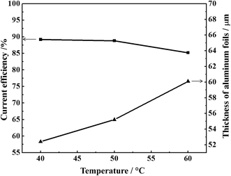 | ||
| Fig. 7 The current efficiency and thickness of aluminium foil at different temperature (current density = 32 mA cm−2, deposit time = 1 h). | ||
3.3 Nucleation behavior of aluminium on GC cathode
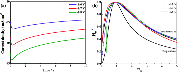
Fig. 8a shows the chronoamperometric current–time transients for AlCl3–[Bmim]Cl using potential between −0.6 V and −0.8 V at 50 °C. There are initial rises in current density which peaks at a particular current density depending on the applied overvoltage and then decays. With time the current density decays due to a diffusion limited steady state process. The initial electrodeposition of aluminium are diffusion limited steady state process on GC electrode in AlCl3–[Bmim]Cl ionic liquid electrolytes. The initial stages of electrodeposition are usually associated with a three-dimensional nucleation growth. For a metal deposition process, a three-dimensional nucleation growth model is usually adopted.29 Furthermore, the nucleation mechanisms are of two different types, namely, instantaneous and progressive.30 The dimensionless current–time relations applicable for diffusion controlled three-dimensional instantaneous and progressive nucleation are given by eqn (1) and (2), respectively.
 | (1) |
 | (2) |
3.4 Growth mechanism of electrodeposited aluminium foils
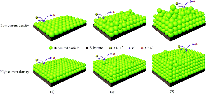
The mechanism for electrodeposited aluminium foils on GC electrode from ILs is complicate and still unknown so far. We just can propose some possible process by referring to the experimental results. As illustrated in Fig. 9, the formation of aluminium foils on GC electrode is divided into 3 stages. At first, a thin compact layer of aluminum is first deposited on the cathode: the oxidized precursor (Al2Cl7−) is electro-reduced to the fully reduced state (Al) and AlCl4− ions at the surface of electrode and produce thin non-dendrite aluminium compact layer by layer-by-layer growth; secondly, dendrites attach to thin compact layer: the dislocation of deposit particles makes aluminium dendrites (as 3D islands formation) and attaches on predeposited 2D aluminium compact layer. The thickness of dendrite-free compact layer depends on the aluminium particles sizes. The fine-grained particles lead to a relatively low deformation and high the density of aluminium particles at high current density. Inversely, the coarse-grained particles result in a relatively high deformation, which are more likely to foils produce dendrite and form loose at low current density. The thickness of foils when the dendrites start occurring are thicker at high current density than the foils at low current density; lastly, the aluminium dendrites continue to grow. Simultaneously, the growth particles are filling up interstice between the dendrites to increase the thickness of compact layer. So, the fine-grained particles are prone to form compact layer.It is significant to find out the thickness value of foils to start occurring dendrite at different current density. The thickness of aluminium foils on GC substrate is evaluated by EDS elemental (Al) mapping image of the cross-section (Fig. S3†). Table 1 shows the thickness of aluminium foils at different current density and deposition time. At current density 57 mA cm−2 and time interval 0.55 and 1 h, the thickness of compact layer is equal to the total thickness. At time interval 2 h, the thickness of compact layer is 184.3 μm. But the total thickness including dendrites is 188.5 μm. It means that compact foil begins to form dendrites (the total thickness is more than the thickness of compact layer). As deposition time delays to 4 h, the compact layer and total thickness increase to 240.2 and 310.8 μm, respectively. The deposition thickness rises when current density and deposit interval time increase. Furthermore, the foils are easy to powder and rupture when the thickness of compact layer is smaller or dendrite is longer at low current density, which marks “a” in the Table 1. These results verify our conjecture as Fig. 9.
| Current density (mA cm−2) | Deposition time (h) | Thickness of compact layer (μm) | Total thicknessb (μm) |
|---|---|---|---|
| a Aluminium foils were not produced at the condition.b Total thickness: the thickness of the aluminium foils including the dendrite. | |||
| 57 | 0.55 | 55.3 | 55.3 |
| 1 | 101.6 | 101.6 | |
| 2 | 184.3 | 188.5 | |
| 4 | 240.2 | 310.8 | |
| 48 | 0.5 | 46.0 | 46.0 |
| 1 | 71.0 | 71.0 | |
| 2 | 118.0 | 118.0 | |
| 4 | 161.0 | 217.2 | |
| 32 | 0.5 | 30.0 | 30.0 |
| 1 | 54.1 | 55.2 | |
| 2 | 70.0 | 120.0 | |
| 4a | — | — | |
| 16 | 0.5a | — | — |
| 1 | 23.5 | 41.0 | |
| 2 | 26.0 | 60.0 | |
| 4a | — | — | |
3.5 Deposition of large aluminium foils on graphite cathode
In order to explore deposition of aluminium foils on other facile carbon substrates for industrial application, amplification experiments of large area aluminium foils have done. Fig. 10 shows that the photograph of smooth graphite cathode (before experiment) and peeled aluminium foil from graphite cathode (after experiment). The deposited aluminium foil was compact and easily peeled from electrode at graphite cathode (10 mm diameter). As shown in Fig. S4† (the SEM image of the large foil), the aluminium foil is non-dendritic and dense. We can completely obtain compact and uniform aluminium foils before the dendrite occurs.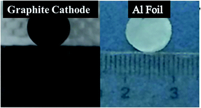 | ||
| Fig. 10 The photograph of graphite cathode and aluminium deposit on graphite cathode (current density = 25 mA cm−2, temperature = 50 °C). | ||
4. Conclusion
The aluminium foils were prepared by low-temperature electrodeposition on carbon substrate using ionic liquid electrolyte (AlCl3–[Bmim]Cl). Aluminium foils are dense, uniform and non-dendritic by high current density and low deposition time. The current efficiency was dependent on different current density varying from 79% to 87%. All of the electrodeposits exhibited a stronger intensity of (200) plane with increasing current density. The nucleation of aluminium on GC electrode is a 3-D instantaneous process at 50 °C. Growth mechanism of aluminium foils was tentatively proposed including first formation of compact layer and dendrite, and following growth of compact layer and dendrite on GC electrode. More significantly, it offers an appealing avenue for dense, uniform, non-dendritic and easily peeled off fabricating process of low-temperature aluminium foils.Acknowledgements
This work was financially supported by the National Natural Science Foundation of China (51104050, 51301050, 51202047, 51404230), the National Key Projects for Fundamental Research and Development of China (2016YFB01003032), the International Cooperation and Exchange of the National Natural Science Foundation of China (51561145020), the Scientific Research Foundation for Heilongjiang Postdoctoral (2016LBH-Z10208), the Natural Science Foundation of Heilongjiang Province of China (E201413), the Technology Foundation for Selected Overseas Chinese Scholar of Heilongjiang Province (No. 159150130002), the Fundamental Research Funds for the Central Universities (HEUCF161501).References
- M. Kondo, H. Maeda and M. Mizuguchi, JOM, 1990, 42, 36–37 CrossRef CAS.
- M. M. Zhang, V. Kamavaram and R. G. Reddy, JOM, 2003, 55, A54–A57 CrossRef.
- B. Wu, R. G. Reddy and R. D. Rogers, Essential Readings in Light Metals, 2001, vol. 2, pp. 1100–1107 Search PubMed.
- A. P. Abbott, G. Frisch, J. Hartley and K. S. Ryder, Green Chem., 2011, 13, 471–481 RSC.
- W. J. Lorenz and G. Staikov, Surf. Sci., 1995, 335, 32–43 CrossRef CAS.
- L. Aldous, D. S. Silvester, C. Villagrán, W. R. Pitner, R. G. Compton, M. Cristina Lagunas and C. Hardacre, New J. Chem., 2006, 30, 1576–1583 RSC.
- Q. X. Liu, E. Abedin, S. Zein and F. Endres, Surf. Coat. Technol., 2006, 201, 1352–1356 CrossRef CAS.
- R. T. Carlin, W. Crawford and M. Bersch, J. Electrochem. Soc., 1992, 139, 2720–2727 CrossRef CAS.
- P. K. Lai and M. Skyllas Kazacos, J. Electroanal. Chem. Interfacial Electrochem., 1988, 248, 431–440 CrossRef CAS.
- T. Jiang, M. J. Chollier Brym, G. Dubé, A. Lasia and G. M. Brisard, Surf. Coat. Technol., 2006, 201, 10–18 CrossRef CAS.
- Y. Zheng, S. J. Zhang, X. M. Lu, Q. Wang, Y. Zuo and L. Liu, Chin. J. Chem. Eng., 2012, 20, 130–139 CrossRef CAS.
- M. Zhang, V. Kamavaram and R. G. Reddy, Light Metals, 2005, vol. 2, pp. 583–588 Search PubMed.
- Q. Liao, W. R. Pitner, G. Stewart, C. L. Hussey and G. R. Stafford, J. Electrochem. Soc., 1997, 144, 936–943 CrossRef CAS.
- D. Pradhan and R. G. Reddy, Metall. Mater. Trans. B, 2012, 43, 519–531 CrossRef CAS.
- D. Pradhan, D. Mantha and R. G. Reddy, Electrochim. Acta, 2009, 54, 6661–6667 CrossRef CAS.
- A. P. Abbott, C. A. Eardley, N. R. S. Farley, G. A. Griffith and A. Pratt, J. Appl. Electrochem., 2001, 31, 1345–1350 CrossRef CAS.
- V. Fleury, J. H. Kaufman and D. B. Hibbert, Nature, 1994, 367, 435–438 CrossRef CAS.
- E. B. Jacob and P. Garik, Nature, 1990, 343, 523–530 CrossRef.
- E. P. Wiechmann, G. A. Vidal and A. J. Pagliero, IEEE Trans. Ind. Appl., 2006, 42, 851–855 CrossRef CAS.
- J. Robinson and R. A. Osteryoung, J. Electrochem. Soc., 1980, 127, 122–128 CrossRef CAS.
- V. Kamavaram, D. Mantha and R. G. Reddy, J. Min. Metall., Sect. B, 2003, 39, 43–58 CrossRef CAS.
- C. C. Yang, Mater. Chem. Phys., 1994, 37, 355–361 CrossRef CAS.
- A. M. Rashidi and A. Amadeh, Surf. Coat. Technol., 2008, 202, 3772–3776 CrossRef CAS.
- Q. Zhang, Q. Wang, S. Zhang and X. Lu, J. Solid State Electrochem., 2013, 18, 257–267 CrossRef.
- G. Yue, S. Zhang, Y. Zhu, X. Lu, S. Li and Z. Li, AIChE J., 2009, 55, 783–796 CrossRef CAS.
- T. Tsuda, T. Nohira and Y. Ito, Electrochim. Acta, 2002, 47, 2817–2822 CrossRef CAS.
- M. C. Kroon, W. Buijs, C. J. Peters and G. J. Witkamp, Green Chem., 2006, 8, 241–245 RSC.
- M. C. Buzzeo, R. G. Evans and R. G. Compton, ChemPhysChem, 2004, 5, 1106–1120 CrossRef CAS PubMed.
- G. Gunawardena, G. Hills, I. Montenegro and B. Scharifker, J. Electroanal. Chem. Interfacial Electrochem., 1982, 138, 225–239 CrossRef CAS.
- A. I. Bhatt, A. M. Bond and J. Zhang, J. Solid State Electrochem., 2006, 11, 1593–1603 CrossRef.
- D. Pradhan and R. G. Reddy, Mater. Chem. Phys., 2014, 143, 564–569 CrossRef CAS.
Footnote |
| † Electronic supplementary information (ESI) available: Schematics of the electrolytic cell, mapping image of the cross-section, EDS analysis of electrodeposited aluminium foils and SEM image of aluminium foils. See DOI: 10.1039/c6ra27217g |
| This journal is © The Royal Society of Chemistry 2017 |

