 Open Access Article
Creative Commons Attribution 3.0 Unported Licence
Nano gold decorated reduced graphene oxide wrapped polymethylmethacrylate for supercapacitor applications†
Gyanaranjan Sahoo,
Niladri Sarkar,
Deepak Sahu and
Sarat K. Swain *
*
Department of Chemistry, Veer Surendra Sai University of Technology, Burla, Sambalpur-768018, Odisha, India. E-mail: swainsk2@yahoo.co.in; Fax: +91-663-2430204; Tel: +91-993-7082348
First published on 12th January 2017
Abstract
Herein, a simple one step synthetic protocol was adopted to fabricate nano gold decorated reduced graphene oxide (r-GO) wrapped polymethyl methacrylate nanohybrids (PMMA/r-GO/Au) for symmetric supercapacitor applications. Synthesized nanohybrids were characterized by UV-visible, Fourier transform infrared spectroscopy (FTIR), X-ray diffraction (XRD), field emission scanning electron microscope (FESEM), and high resolution transmission electron microscope (HRTEM). The gold nanoparticles were found to be distributed uniformly on the surface of r-GO layers with a basement of PMMA. Thermal stability of the fabricated PMMA/r-GO/Au nanohybrid was investigated by thermogravimetric analysis (TGA) and an improvement in thermal stability was observed as compared to PMMA and PMMA/r-GO nanohybrids. Electrochemical performance of the PMMA/r-GO/Au nanohybrids was investigated as electrode material in three electrode systems in addition to a symmetric cell in a two electrode system with 1 M H2SO4 medium. The fabricated PMMA/r-GO/Au nanohybrid-based symmetric cell delivered significantly higher energy density of 29.46 W h kg−1 at a power density of 235 W kg−1 as compared to that of the PMMA/r-GO-based symmetric cell. The improved energy storing capacity of this material was assigned from the synergistic effect of r-GO and Au NPs in a typical layered arrangement. The substantial improvement in electrochemical performance may enable the synthesized ternary nanohybrid for supercapacitor applications.
1. Introduction
Two dimensional graphene sheets (GS) with sp2 hybridized carbon networks have recently grabbed the 21st century limelight for fabrication of multifunctional advanced materials due to its novel optical, mechanical, electronic, thermal, and biological properties.1–3 Graphenes are generally processed through an intermediate step of graphene oxide (GO) by chemical oxidation of stacked graphite.4 Intermediate graphene oxides (GO) are quite stable in aqueous suspension and are widely used for fabrication of polymer nanocomposites due to a variety of oxygenated functional groups.5,6 Among different synthetic polymers, poly methyl methacrylate (PMMA) is widely used for preparation of different polymeric hybrid materials due to its low cost, easy melt processability, ability to mould into any shape, optical clarity, and good physical–mechanical properties.7 Because of the unique properties of individual nanostructures and synergistic effects, nanocomposites have attracted a great deal of attention in the areas of bio-sensing, energy conversion, and energy storage.8–10 In order to restore the excellent electronic properties of graphenes, graphene oxides (GO) are usually reduced within the composite network by hydrazine hydrate. De-oxygenation of GO leads to removal of a significant fraction of the contained oxygen and thereby the result is known as reduced graphene oxide (r-GO). The 2-D architecture of graphene limits its wide applicability in smart electronic devices. Hence, the dimensional transformation of graphene from 2-D to 3-D to enlarge the reactive surface area of it is a great challenge for forthcoming research. Several strategies have been taken into account for this purpose including porous foam shape 3-D carbon films,11 fibered structures with carbon composite,12 a hand rolling and skiving method,13 mechanically wrinkled graphene film,14 and patterning on a structured template.15The unique combination of polymeric latex and nanofillers in polymer nanocomposites was recently highlighted for their enhanced properties at lower filler content which resulted from the excluded volume created by the polymeric microspheres/latex that forced the fillers into interstitial spaces between polymer particles during drying. This process led to a specific arrangement of the fillers in the polymer matrix defined as a “segregated network” and was explored to fabricate graphene-based composites.16 In connection to this, recently a highly conducting composite was fabricated by the combination of PMMA latex and r-GO sheets.17 PMMA latex has a wide applicability in electrode materials. The combination of PMMA with CNT was also reported for use as electrode material for a sensitive amperometric detector for microchip capillary electrophoresis (CE).18 Decoration of silver nanowires in PMMA/Ag films also results in a highly conducting material.19
On the other hand, decoration of transition metal and metal oxide nanoparticles onto a graphene sheet causes an obstacle for re-stacking of graphene layers and also introduces some extraordinary behaviors including optical, electrical, magnetic, and catalytic properties.20–23 These nano scale composites are widely used in a variety of applications ranging from fuel cells to sensors24 and capacitors to storage batteries.25,26 Among different transition metal nanoparticles, gold nanoparticles (Au NPs) are widely known for their catalytic, energy storage, and bio-medical applications.27 Due to a strong synergetic effect between graphene and Au nanoparticles, a graphene/Au nanohybrid architecture successfully demonstrated its applicability as supercapacitor. In a recent report, Au nanoparticles with a diameter of about 10 nm were efficiently used as nano spacers to enhance the supercapacitance property of electrochemically reduced graphene oxide (r-GO). The enhancement is surprisingly very high and it is from 4.99 F g−1 (when no spacers are used) to 174.2 F g−1 (when gold nano spacers are introduced).28 Compared with secondary batteries, electrochemical capacitors, also known as supercapacitors or ultra-capacitors, exhibit faster and higher power capability, long life, wide thermal operating range, and low maintenance cost.29,30 According to charge–discharge mechanisms, supercapacitors are categorised into two classes: (i) electrical double-layer capacitors (EDLCs), where the electrical charge is stored at the interface between the electrode and the electrolyte, and (ii) pseudocapacitors, where capacitance arises from reversible faradaic reactions taking place at the electrode/electrolyte interfaces. Carbon materials,31 transition metal oxides and hydroxides,32,33 and conducting polymers34–36 have been widely used as the most promising materials for supercapacitor electrodes.
In the present study, we designed a rational strategy to fabricate ternary PMMA/r-GO/Au nanohybrids with the aim to enhance the super capacitive property of r-GO on a polymer support by means of better exfoliation of graphene layers. Polymer support also helps to increase the available reactive surface area for formation of Au NPs. Monodispersed polymethyl methacrylate (PMMA) spheres were used as hard templates for designing the 3-D architecture of nano gold decorated reduced graphene oxides. Here, PMMA was used for their unique spherical structures and good mechanical strength besides their nonconducting properties. Removal of PMMA latex through a high temperature annealing process was not done, as it may cause the restacking of graphene layers at high temperature.37 Furthermore, a very low concentration of MMA was used because the non-conducting nature of PMMA does not affect so much the capacitance of the integrating combination of r-GO and Au nanoparticles. The whole fabrication technique was planned in a “One pot” synthetic protocol by the in situ polymerization of methyl methacrylate (MMA) through free radical initiated pathways. The successive addition of an aqueous suspension of graphene oxide (GO) and chloroauric acid solution (HAuCl4·3H2O) during progression of the polymerization of MMA and subsequent reduction of Au3+ to Au gives a three layer arrangement, whereas the basement is constructed of PMMA micro spheres. The middle layer is attributed by the extended graphene layer and the upper layer is formed by in situ formed gold nanoparticles which are decorated onto the exposed surface of reduced graphene oxide (r-GO). The hybrid nanocomposites (PMMA/r-GO/Au) were characterized with FT-IR, XRD, UV-visible spectroscopy, FESEM, and HRTEM. The supercapacitance property of the ternary nanohybrid was investigated using a three-electrode electrochemical cell as well as a two electrode configured symmetric cell in 1 M H2SO4 medium.
2. Experimental
2.1 Materials
The monomer methyl methacrylate (MMA) was purchased from Merck, Germany and used after further purification as reported earlier.38,39 The initiator potassium persulphate (KPS) was also purchased from Merck, Germany and used as such. The metal precursor, chloroauric acid (HAuCl4), was purchased from Sigma-Aldrich and also used as received. Graphite powder (average diameter 500 μm) was purchased from Loba Chemical Pvt. Ltd., Mumbai, India. Other chemicals were of analytical grade and used without any further purification. All solutions were prepared using double distilled water.2.2 Preparation of PMMA latex
PMMA latex was prepared by emulsifier-free emulsion polymerization. In a typical procedure, 2.82 g of methyl methacrylate (MMA) was dispersed in 20 mL of double distilled water with stirring at 400–600 rpm and bubbled with nitrogen for 30 min. The temperature was increased to 60 °C followed by the addition of 2 mL of 0.1 (M) potassium persulfate (KPS) solution. The polymerization was carried out under continuous stirring for 3 h. The obtained colloidal suspension of PMMA latex was filtered, washed with methanol 3 times, and dried at 60 °C for 48 h.2.3 Preparation of PMMA/r-GO/Au nanohybrids
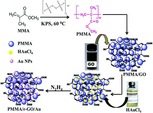
Nano gold decorated reduced graphene oxide wrapped polymethyl methacrylate (PMMA/r-GO/Au) nanohybrids were synthesized by an in situ surfactant-free emulsion polymerization technique. Polymerization was carried out in a round bottom flask with inlet and outlet tubes for passing nitrogen. According to the procedure, 2.82 g of methyl methacrylate (MMA) was dispersed in 20 mL of double distilled water with stirring at 400–600 rpm and bubbled with nitrogen for 30 min. This stirring speed was maintained throughout the experiment as it had no remarkable effect on the rate of polymerization. Then, the reaction temperature was increased to 60 °C followed by the addition of 2 mL of 0.1 (M) potassium persulfate (K2S2O8) solution to initiate polymerization. After 20 min of polymerization, 3 mL of GO dispersion (0.68 mg mL−1) was injected in to it. Graphene oxide (GO) was prepared as per the modified reported method.40,41 After 30 min of the addition of (GO), 1 mL of freshly prepared 0.2 mM HAuCl4 solution was added to the mixture of PMMA–GO solution followed by stirring for 20 minutes to obtain homogeneous mixtures of gold salt, PMMA, and GO. Then the system temperature was increased to 80 °C. To this homogenized solution, 4.5 μL of hydrazine hydrate solution was added to initiate the formation of Au NPs and subsequent reduction of GO. Stirring was continued for 3 h and then the process of polymerization was arrested by addition of 1 mL 0.1 M ammonium ferrous sulphate [(NH4)2Fe(SO4)2·6H2O] solution. The precipitated nanocomposites were filtered, washed with deionized water, and dried at 60 °C for 48 h. The whole synthetic protocol is schematically represented in Scheme 1.2.4 Characterization of prepared nanohybrid
The UV-visible spectra of PMMA, PMMA/r-GO, and PMMA/r-GO/Au nanohybrids were obtained with the help of a UV-visible spectrophotometer (model UV-2450, Shimadzu Corporation, Japan). X-ray diffraction (XRD) patterns were obtained using a Rigaku X-ray machine operating at 40 kV and 150 mA. FTIR spectra of the prepared samples (as KBr pellets) were recorded using a Shimadzu IR Affinity-1 Fourier infrared spectrophotometer in the range of 4000 to 400 cm−1. The surface morphology of the nanohybrid was studied with the help of a field emission scanning electron microscope (FESEM) from Jeol Ltd., Japan (model 5200 with ×30![[thin space (1/6-em)]](https://www.rsc.org/images/entities/char_2009.gif) 000 magnification). Distribution of the in situ formed gold nanoparticles on the r-GO surface was examined using Tec-nai 12, Phillips high resolution transmission electron microscope (HRTEM) operating at 120 kV. The AFM measurement was performed on a sample coated mica foil using Pico plus 5500 ILM AFM, with a piezo scanner maximum range of 100 μm.
000 magnification). Distribution of the in situ formed gold nanoparticles on the r-GO surface was examined using Tec-nai 12, Phillips high resolution transmission electron microscope (HRTEM) operating at 120 kV. The AFM measurement was performed on a sample coated mica foil using Pico plus 5500 ILM AFM, with a piezo scanner maximum range of 100 μm.
Thermogravimetric analysis (TGA) for the prepared samples was performed using a TGA apparatus, model DTG-60 by Shimadzu Corporation, Japan. The sample was analyzed under nitrogen purge and heating cycle at 10 degree per min. All electrochemical measurements were performed with a CH instrument 660 D electrochemical work station. Electrochemical properties of PMMA/r-GO/Au nanohybrids, as electrode material as well as symmetric cell, were investigated in a potential window of −0.2 V to 0.8 V. For three electrode electrochemical systems, an Ag/AgCl electrode was used as the reference electrode, a Pt electrode as a counter electrode and the synthesized PMMA/r-GO/Au nanohybrid was used as the working electrode. To investigate the electrochemical properties of the symmetric cell based on PMMA/r-GO and PMMA/r-GO/Au nanohybrids, a two-electrode configured electrochemical setup was fabricated by assembling the same active mass of the nanohybrid material as the cathode and anode, and separated from each other with a separator. All electrochemical analyses were carried out in 1 M H2SO4 solution as the electrolyte.
3. Results and discussions
3.1 Structural analysis
The UV-visible absorption spectra of GO, PMMA, PMMA/r-GO, and PMMA/r-GO/Au nanohybrids are compared in Fig. S1.† The absorption peaks of GO (inset Fig. S1†) at 230 nm and 304 nm are due to the π–π* transition of aromatic C–C and n–π* transition of C![[double bond, length as m-dash]](https://www.rsc.org/images/entities/char_e001.gif) O, respectively. Upon chemical reduction with hydrazine solution on GO, peaks at 230 nm and 304 nm disappeared and a new peak appeared at 262 nm, indicating the generation of r-GO. Upon reduction, the absorption peak for π–π* of GO is red shifted due to restoration of electronic conjugation, reflecting the increased π electron concentration and structural ordering. Further, in UV-visible spectra of PMMA/r-GO/Au nanohybrids, a surface plasmon resonance (SPR) peak of Au NPs is generated at 621 nm (ref. 42–44) along with the absorption peak of r-GO at 270 nm.
O, respectively. Upon chemical reduction with hydrazine solution on GO, peaks at 230 nm and 304 nm disappeared and a new peak appeared at 262 nm, indicating the generation of r-GO. Upon reduction, the absorption peak for π–π* of GO is red shifted due to restoration of electronic conjugation, reflecting the increased π electron concentration and structural ordering. Further, in UV-visible spectra of PMMA/r-GO/Au nanohybrids, a surface plasmon resonance (SPR) peak of Au NPs is generated at 621 nm (ref. 42–44) along with the absorption peak of r-GO at 270 nm.
3.2 FT-IR analysis
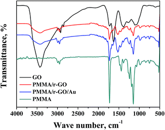
FTIR analysis was performed and corresponding spectra of PMMA, GO, PMMA/r-GO, and PMMA/r-GO/Au nanohybrids are shown in Fig. 1. The FTIR spectrum of PMMA has a peak at 3007 cm−1 which is assigned to the vibrational peak of C–H stretching vibration whereas the peak at 1732 cm−1 is due to acrylate carboxyl groups. The FTIR band at 1388 cm−1 is due to O–CH3 bending vibrations, whereas the peak at 1242 cm−1 is assigned to the twisting mode of the –CH2 group in PMMA. The FTIR peak of PMMA at 1439 cm−1 is assigned to the bending of C–H bonds in the –CH3 group. The strong peak at 1148 cm−1 is associated with the stretching vibration of the C–O bond in the C–O–C moiety.45 FTIR of graphene oxide (GO) shows the characteristic IR vibrations of C–O, C–O–C, and C–OH bonds at 1068 cm−1, 1256 cm−1, and 1370 cm−1, respectively. The FTIR peak at 1624 cm−1 is ascribed to skeletal vibration of the graphene domain (C![[double bond, length as m-dash]](https://www.rsc.org/images/entities/char_e001.gif) C). For GO, the FTIR peaks at 2915 and 2852 cm−1 are due to C–H stretching vibration. The peak at 3419 cm−1 of GO confirms the presence of numerous –OH functionality on its surface. In the case of PMMA/r-GO/Au nanohybrids, GO is reduced with hydrazine hydrate within the composite network during in situ generation of gold nanoparticles. Upon reduction, the FTIR peaks of C–O and C–O–C of GO are weakened and the FTIR peak at 3419 cm−1 corresponding to the –OH functionality is reduced. The FTIR peak of the
C). For GO, the FTIR peaks at 2915 and 2852 cm−1 are due to C–H stretching vibration. The peak at 3419 cm−1 of GO confirms the presence of numerous –OH functionality on its surface. In the case of PMMA/r-GO/Au nanohybrids, GO is reduced with hydrazine hydrate within the composite network during in situ generation of gold nanoparticles. Upon reduction, the FTIR peaks of C–O and C–O–C of GO are weakened and the FTIR peak at 3419 cm−1 corresponding to the –OH functionality is reduced. The FTIR peak of the ![[double bond splayed left]](https://www.rsc.org/images/entities/char_e009.gif) C
C![[double bond, length as m-dash]](https://www.rsc.org/images/entities/char_e001.gif) O group of GO at 1728 cm−1 is also reduced in the composite network, confirming formation of the r-GO network. In the case of PMMA/r-GO and PMMA/r-GO/Au nanohybrids, presence of a
O group of GO at 1728 cm−1 is also reduced in the composite network, confirming formation of the r-GO network. In the case of PMMA/r-GO and PMMA/r-GO/Au nanohybrids, presence of a ![[double bond splayed left]](https://www.rsc.org/images/entities/char_e009.gif) C
C![[double bond, length as m-dash]](https://www.rsc.org/images/entities/char_e001.gif) O peak is also evidenced even after the reduction because of contribution of
O peak is also evidenced even after the reduction because of contribution of ![[double bond splayed left]](https://www.rsc.org/images/entities/char_e009.gif) C
C![[double bond, length as m-dash]](https://www.rsc.org/images/entities/char_e001.gif) O groups from PMMA. However, the FTIR peak intensity of
O groups from PMMA. However, the FTIR peak intensity of ![[double bond splayed left]](https://www.rsc.org/images/entities/char_e009.gif) C
C![[double bond, length as m-dash]](https://www.rsc.org/images/entities/char_e001.gif) O groups is found to be less as compared to pure PMMA.46 In the case of the FTIR spectrum of PMMA/r-GO nanohybrids, the pattern is almost the same as PMMA/r-GO/Au nanohybrids without showing any other distinct peaks.
O groups is found to be less as compared to pure PMMA.46 In the case of the FTIR spectrum of PMMA/r-GO nanohybrids, the pattern is almost the same as PMMA/r-GO/Au nanohybrids without showing any other distinct peaks.
3.3 XRD analysis
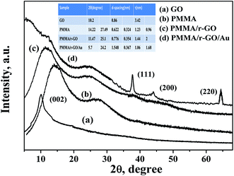
The structural investigation of nano gold imprinted PMMA/r-GO nanohybrid was carried out using XRD (Fig. 2). The XRD pattern of pure PMMA latex shows two amorphous diffraction peaks at 2θ values of 14.22° and 27.49°. From the XRD pattern of GO, a strong diffraction peak at 2θ value of 10.2° is assigned to the presence of (002) plane. In general, graphite in its diffraction pattern shows a strong crystalline peak at 2θ value of 26.5° which is due to the compact arrangement of graphene layers with interlayer spacing of 0.335 nm. On oxidizing the layered graphite, there is a probability of incomplete oxidation and simultaneous presence of graphite and GO peaks. But disappearance of the graphitic peak from the XRD pattern of GO indicates complete oxidation of graphite. Furthermore, the calculated d-spacing of GO is 0.86 nm, higher than the layered graphite structure. The XRD pattern of PMMA/r-GO shows two diffraction peaks at 2θ values of 11.47° and 25.1° with corresponding interlayer spacing of 0.776 nm and 0.354 nm, respectively. The increased value of interlayer spacing of PMMA peaks may be assigned to the strong interaction of PMMA and GO. On the other hand, in the case of PMMA/r-GO nanohybrids, the d spacing for r-GO is found to be 0.354 nm. The decrease in the value of d-spacing in PMMA/r-GO nanohybrids confirms the chemical reduction of GO. For GO reinforced PMMA, a crystalline peak of GO is not observed. This fact can be attributed to the dilution effect of the polymer matrix because of which the regular and periodic structure is not maintained. In other words, GO sheets are fully exfoliated and randomly dispersed in the PMMA matrix. In the case of PMMA/r-GO/Au nanohybrids, four distinct diffraction peaks are observed at 2θ values of 5.7°, 24.21°, 28.04°, 37.64°, 44°, and 64.46°, respectively. The XRD peak at 2θ value of 24.21° is assigned to the presence of r-GO with a d-spacing of 0.367 nm, slightly higher as compared to PMMA/r-GO nanohybrids. This fact can be attributed to the strong interaction of in situ generated Au NPs and GO sheets, leading to better exfoliation of graphene layers in PMMA/r-GO/Au nanohybrids. Moreover, the XRD peak at 5.7° of PMMA/r-GO/Au nanohybrid is assigned for PMMA and a shift to a lower angle side as compared to pure PMMA is due to the decrease in crystallite size of PMMA microspheres in the presence of r-GO layers and Au NPs. A similar type of result was also reported in our earlier report.47 Peaks at 2θ values of 37.64°, 44°, and 64.46° are assigned due to different crystalline phases of in situ formed nano gold and those can be indexed as (111), (200), and (220), respectively.3.4 Morphological study
Surface morphology of the prepared PMMA/r-GO/Au ternary nanocomposite is shown in the FESEM images (Fig. 3). Fig. 3a and b shows the monodispersed spherical PMMA latex which is formed due to emulsifier-free emulsion polymerization of methyl methacrylate (MMA) with ammonium persulphate as initiator. Controlled addition of graphene oxide (GO) during in situ polymerization of PMMA, gives a layer coverage above the spherical PMMA latex (Fig. 3d). During in situ formation of Au NPs in PMMA/r-GO/Au nanohybrids, the expanded GO surface with oxygenated functional groups provides an effective nucleation and binding site for the Au NPs to restrict the further growth of Au NPs. Moreover, generation of gold nanoparticles in the same reaction vessel gives a uniform decoration on the highly exfoliated graphene oxide layer (Fig. 3e). Hence, a ternary nanocomposite appeared in FESEM images (Fig. 3c–e). Such kind of layer by layer architecture has also been evidenced for hierarchical MnO2/polypyrrole (PPy)/r-GO nanocomposites and this unique pattern was successfully used in a supercapacitor application.48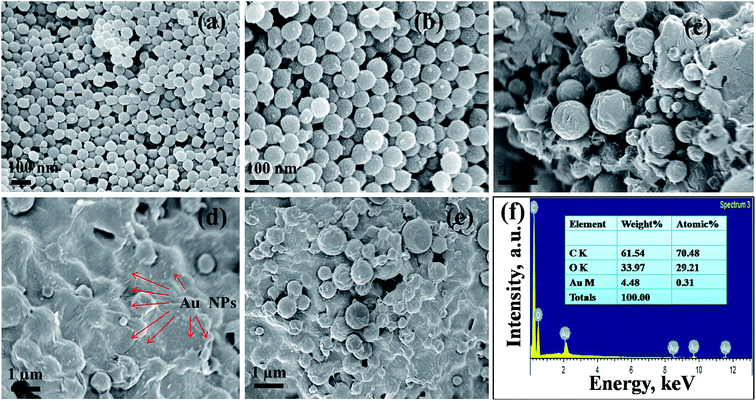 | ||
| Fig. 3 FESEM micrographs of (a, b) pure PMMA, (c–e) PMMA/r-GO/Au nanohybrid, and (f) energy-dispersive spectra of PMMA/r-GO/Au nanohybrids. | ||
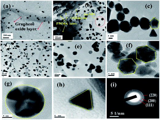
The presence of gold nanoparticles on graphene oxide-coated PMMA latex is evidenced through EDS analysis and presented in Fig. 3f along with its elemental composition. The morphological evolution of the Au nanoparticles is critically dependent on the substrate surface. The role of the graphene oxide-coated PMMA surface on the size and shape of Au nanoparticles is demonstrated in the HRTEM images (Fig. 4). Fig. 4a shows the uniform decoration of Au NPs on the r-GO surfaces, whereas Fig. 4b shows the appearance of r-GO-covered PMMA microspheres along with the decorating gold nanoparticles on its surfaces. The different structural geometry of the in situ formed gold nanoparticles on the exfoliated graphene oxide layer is observed (Fig. 4c–e). The majority of the gold particles are spherical in nature with a lattice fringe of 0.23 nm. Apart from the spherical geometry, HRTEM images also display the co-existence of trigonal, pentagonal, and hexagonal geometry of the in situ formed gold nanoparticles (Fig. 4c and f–h). Structural variation of colloidal gold nanoparticles is influenced by the presence of surfactants or capping agents that regulate the growth of the crystal in a particular direction.49 If single crystalline seeds are primarily produced, then the final product is composed of monodispersed tetrahedral and octahedral cubes. From literature, it is noticed that if multi-twinned particles with decahedral shapes are primarily formed then the final product is mainly composed of nanorods and nanowires with a remarkable multi-twinned structure with pentagonal cross sectional geometry.50 This implies that the final product is entirely dependent on the starting geometry of the nanoparticles formed. Sometimes, concentration of the metal precursor plays an important role in order to generate gold nanoparticles with different morphology.51 In the present context, the structure of gold nanoparticles can be attributed from its starting geometry. As the nanoparticles are allowed to form and grow on the r-GO sheets that are extended on the PMMA microsphere, this does not provide the same geometric environment everywhere. However, with the progression of time; this leads to more anisotropy in the observed geometry of the gold nanoparticles.52 In other words, the change in particle shape is attributed to the contact angle variation of the metal precursor and the exposed surfaces of r-GO-covered PMMA latex. This explanation is in accordance with a statement in an earlier report53 involving the study of a different structural geometry of Au NPs during the synthesis of free standing Au and Ag–PMMA films. The crystalline phases of spherically shaped gold nanoparticles are encountered through the SAED pattern of the PMMA/r-GO/Au ternary nanohybrid (Fig. 4i).
3.5 AFM analysis
AFM analysis was performed to investigate the surface roughness and dimensions of pure PMMA and PMMA/r-GO/Au nanohybrids. The surface roughness can be calculated by measuring the height of the peaks observed in the out of plane (z) direction, which is normally done using the AFM. The fracture surfaces of neat PMMA and PMMA/r-GO/Au nanohybrids are shown in two and three dimensional AFM images of Fig. 5. The images are captured with a scan size between 0.0 μm to 20 μm at a scan rate of 0.5 lines per second. Images are processed by flattening using Pico view 1.12 version software. From the images, it is found that the surfaces of nanohybrids show elevated peaks, evidencing extremely rough surfaces. The average roughness of PMMA is 106 nm (Fig. 5a–c) and can be attributed from the monodispersed spherically shaped PMMA latex, whereas the coverage of graphene oxide (GO) may decrease the average roughness of the materials. But the in situ generation of gold nanoparticles increases the average roughness of PMMA/r-GO/Au nanohybrids at nanoscale (Fig. 5d–f). The increase in roughness of nanohybrids with the in situ generation of nanoparticles is in accordance with our earlier report.54 The average roughness of nanohybrids is found to be 134.0 nm. The high surface roughness of the fabricated nanohybrids may be beneficial for the allowance of insertion/extraction of cations and anions from aqueous electrolyte solution.55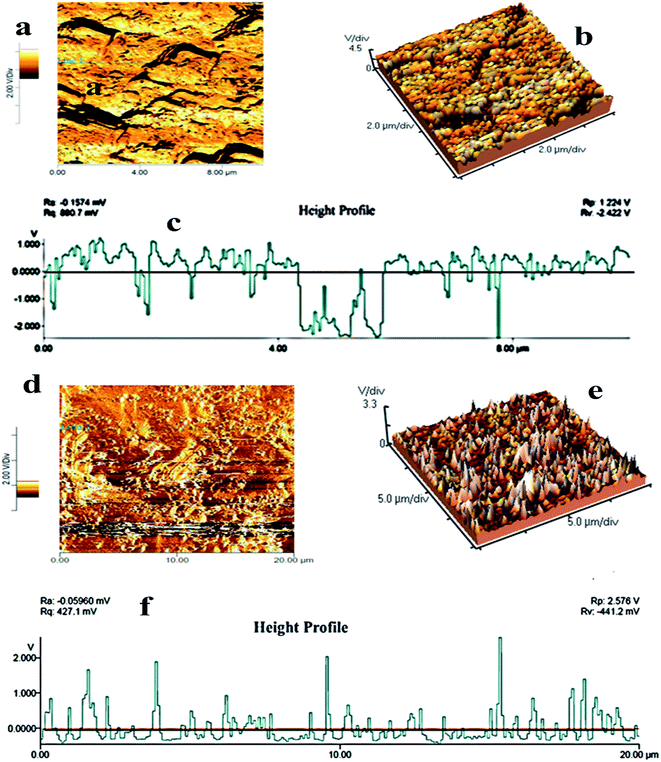 | ||
| Fig. 5 AFM images of (a, b) pure PMMA, (d, e) PMMA/r-GO/Au nanohybrids; (c) and (f) are the height profiles of pure PMMA and PMMA/r-GO/Au nanohybrids. | ||
3.6 Thermal analysis
Fig. S2† shows the thermal decomposition profile of pure PMMA, PMMA/r-GO, and PMMA/r-GO/Au nanohybrids. Thermal decomposition of pure PMMA occurs in a three step weight loss processes. The first thermal degradation, just below 100 °C, is attributed to the expulsion of water molecules from surface of PMMA, whereas the second step of degradation occurred at around 240 °C and is due to the structural degradation of PMMA. The third and final step of thermal decomposition started around 350 °C and can be assigned to the oxidation of partially decomposed PMMA. For the synthesized PMMA/r-GO/Au nanohybrids, thermal stability increases significantly as compared to pure PMMA and PMMA/r-GO nanohybrids. Enhanced thermal stability of the PMMA/r-GO/Au nanohybrid may be attributed to the synergistic effect of r-GO and Au NPs in a compact layered arrangement on spherically designed PMMA latex. The PMMA/r-GO nanohybrids with in situ generated Au NPs show a high thermal stability as compared to PMMA. PMMA/r-GO nanohybrids with a residual mass of more than 30% are shown in Table 1.| Sample | Decomposition percentage as a function of time | |||||
|---|---|---|---|---|---|---|
| 100 °C | 200 °C | 300 °C | 400 °C | 600 °C | 800 °C | |
| PMMA | 98.64 | 98.50 | 96.49 | 14.15 | 0.30 | 0.09 |
| PMMA/r-GO | 99.88 | 99.64 | 99.20 | 90.36 | 31.38 | 22.00 |
| PMMA/r-GO/Au | 99.44 | 99.31 | 98.70 | 96.09 | 40.80 | 30.91 |
3.7 Electrochemical properties of PMMA/r-GO/Au nanohybrids
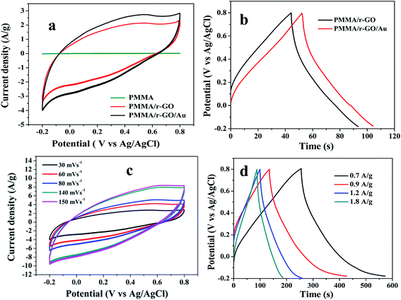
To evaluate electrochemical characteristics of the ternary PMMA/r-GO/Au nanohybrids as electrode material, CV curves in 1 M H2SO4 electrolyte were performed at the potential window from −0.2 to 0.8 V versus Ag/AgCl. Fig. 6a shows the comparative CV curve of pure PMMA, PMMA/r-GO, and PMMA/r-GO/Au nanohybrids as electrode materials. The electrochemical capacitance of pure PMMA is very small and can be neglected. Electrochemical capacitance is proportional to CV curve area. Apparently, the CV curve area of PMMA/r-GO/Au nanohybrids is larger than that of PMMA/r-GO nanohybrids. The galvanostatic charge/discharge curves of PMMA/r-GO and PMMA/r-GO/Au nanohybrids are shown in Fig. 6b.Fig. 6c shows the CV curves of PMMA/r-GO/Au nanohybrids at different scan rates of 30, 60, 80, 140, and 150 mV s−1 and all the curves represent a typical rectangular-like shape implying the characteristic double layer capacitance of the electrode materials.56
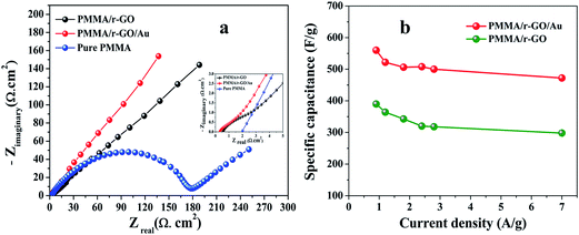
The galvanostatic charge/discharge curves of PMMA/r-GO/Au nanohybrids at various current densities of 0.7, 0.9, 1.2, and 1.8 A g−1 are illustrated in Fig. 6d. The variation of C/DC curves of PMMA/r-GO/Au nanohybrids at higher current densities are illustrated in Fig. S3.† Discharge times decrease with an increase in current density. During the charge and discharge processes, the charge curve of PMMA/r-GO/Au nanohybrids is almost symmetric to its corresponding discharge counterpart with a slight curvature, suggesting a high reversibility of the hybrid materials. A close look at the galvanostatic charge–discharge (C/DC) curves of PMMA/r-GO and PMMA/r-GO/Au nanohybrids (Fig. 6d) enables interpreting the efficiency of electrode material as a supercapacitor by accounting the charging and discharging times. Fig. 7a displays the electrochemical impedance spectroscopic (EIS) measurements of pure PMMA, PMMA/r-GO, and PMMA/r-GO/Au nanohybrid electrodes. An ideal supercapacitor is assigned by the small depressed semicircle at high frequency and the imaginary part of the impedance in the low frequency region being perpendicular to the real part. The internal resistance (Rs) of the mentioned nanohybrid materials in a three electrode electrochemical cell was estimated from the intersection of the Nyquist plot in the x-axis in the high frequency region. These values are dependent on the ionic resistance of the electrolyte, the intrinsic resistance of the active material, and the contact resistance at the electrode/electrolyte interface.57 It is observed that Rs values of pure PMMA, PMMA/r-GO, and PMMA/r-GO/Au nanohybrids are 1.98, 0.58, and 0.31 Ω cm2; respectively. Another electrochemical parameter, Rct, charge transfer resistance, is related to the arc of the semi-circle from the high to low frequency region. This parameter is very essential for encountering the interfacial processes of counter-ions through the electrode/electrolyte interface. The estimated Rct are 172.98, 2.09, and 1.48 Ω cm2, respectively for pure PMMA, PMMA/r-GO, and PMMA/r-GO/Au nanohybrid electrodes. The higher value of Rs and Rct of pure PMMA can be assigned from its non-conducting nature. Lower values of Rs and Rct of PMMA/r-GO/Au nanohybrid electrode, as compared to the PMMA/r-GO electrode, implies a better capacitive performance. Here, in situ generated nano gold with average diameter of about <30 nm acts as a nano spacer and inhibits the re-stacking of the reduced graphene oxide (r-GO) to create more available space for the electrolyte ions. Moreover, the gold exhibits a substantial improvement in its conducting properties at nano dimensions by creating a conducting network within the 3-D architecture of PMMA/rGO/Au nanohybrids for the charge transport of electrolyte ions. Hence, incorporation of Au NPs contributed an enhancement of the specific capacitance performance of the materials.
Further, the PMMA/r-GO/Au nanohybrid electrode exhibits a more vertical line than PMMA/r-GO at low frequency which is a distinct characteristic of an excellent supercapacitor. The positive influence of Au NPs in PMMA/r-GO/Au nanohybrids to enhance its supercapacitance value can be ascribed from the synergistic effect between r-GO and Au NPs. Specific capacitance (C) of the electrode materials can be calculated from the charge/discharge curves of the electrode materials by eqn (1):
| C = IΔt/ΔVm | (1) |
3.8 Electrochemical performance of symmetric supercapacitors
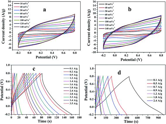
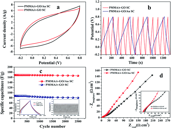
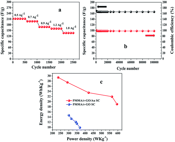
To explore the capacitive performances of as-synthesized PMMA/r-GO and PMMA/r-GO/Au nanohybrids, two symmetric cells were fabricated based on PMMA/r-GO//PMMA/r-GO and PMMA/r-GO/Au//PMMA/r-GO/Au systems using 1 M H2SO4 as electrolyte. Fig. 8a and b represent the cyclic voltammogram (CVs) of the two electrode configured PMMA/r-GO//PMMA/r-GO and PMMA/r-GO/Au//PMMA/r-GO/Au systems in a potential window of −0.2 V to 0.8 V with various scan rates, such as 10, 40, 50, 60, 80, 100, 120, and 140 mV s−1. For the PMMA/r-GO/Au//PMMA/r-GO/Au cell, the CV curves are quasi-rectangular in nature, indicating the characteristic electrical double layer of the symmetric cell. Additionally, the absence of any redox peaks on CV curves implies that the charge/discharge process of active materials is carried out at a pseudo-constant rate over the entire potential window. The cell maintains the quasi-rectangular shape of CVs even at a high scan rate of 140 mV s−1 indicating ideal capacitive behaviors and desirable fast charging/discharging property of power devices. For the PMMA/r-GO//PMMA/r-GO cell, the CV curves also appeared as rectangular in shape in the same potential window (−0.2 to 0.8 V). In order to evaluate electrochemical performance at higher voltages, the cells were charged and discharged between −0.2 to 0.8 V at various current densities. The galvanostatic charge/discharge (C/DC) curves of PMMA/r-GO//PMMA/r-GO and PMMA/r-GO/Au//PMMA/r-GO/Au cells at different current densities are presented in Fig. 8c and d; revealing the linear voltage–time relation, characteristics of an electrical double layer.51 The in situ generation of Au NPs on the r-GO surface acts as a nano spacer to create more available space either side of the wall for storing and transportation of electrolyte ions. This may be ascribed to the improved charge/discharge property of the symmetric cell. As capacitance is directly related to the area under the CV curve, the better capacitance property of PMMA/r-GO/Au//PMMA/r-GO/Au cell is assured by the larger area of its CV curve as compared to the PMMA/r-GO//PMMA/r-GO cell at a scan rate of 100 mV s−1 (Fig. 9a). In Fig. 9b, C/DC curves of PMMA/r-GO//PMMA/r-GO and PMMA/r-GO/Au//PMMA/r-GO/Au symmetric cells are compared at a current density of 0.9 A g−1. From this figure it can be concluded that the PMMA/r-GO/Au//PMMA/r-GO/Au cell offers higher capacitance as compared to PMMA/r-GO//PMMA/r-GO symmetric cell. Symmetrical features of the C/DC curves of both the cells express the excellent electrochemical reversibility and capacitive behavior.58It can also be noted from the inset of Fig. 9c that the charge and discharge times of the cells are almost the same, suggesting 100% coulombic efficiency. To understand the capacitance behavior of the fabricated symmetric cells in 1 M H2SO4 medium, an electrochemical impedance measurement (EIS) was carried out. Fig. 9d displays the Nyquist plots of the PMMA/r-GO//PMMA/r-GO and PMMA/r-GO/Au//PMMA/r-GO/Au symmetric cells recorded at open circuit voltage. Nyquist plots of an excellent supercapacitor show a very small kinetic arc at high frequencies implying a charge transfer controlled regime and a straight line at low frequencies indicating the capacitive regime. The PMMA/r-GO/Au symmetric cell exhibited a smaller semi-circle and a straight line close to 90° to the real axis in the low frequency region, thus demonstrating enhanced capacitor performance of the PMMA/r-GO/Au symmetric cell. On the other hand, the PMMA/r-GO//PMMA/r-GO symmetric cell exhibits a slightly larger Rct value as compared to the PMMA/r-GO/Au//PMMA/r-GO/Au symmetric cell. The larger value of Rct for the PMMA/r-GO//PMMA/r-GO cell as compared to the PMMA/r-GO/Au//PMMA/r-GO/Au cell can be ascribed to the presence of non-conducting PMMA microspheres in the 3-D network of reduced graphene oxide. In the case of PMMA/r-GO/Au//PMMA/r-GO/Au cell, the effect of PMMA on the larger value of Rct was found to be reduced due to incorporation of conducting gold nano particles within the 3-D network of PMMA/r-GO/Au nanohybrids. In order to realize the efficiency of the fabricated PMMA/r-GO/Au//PMMA/r-GO/Au symmetric cell, rate performance is a key factor. The specific capacitances obtained from the C/DC curves were 212, 198, 169, 158, and 137 F g−1 at current densities of 0.5, 0.7, 0.9, 1.2, and 1.8 A g−1 respectively.
The cyclic behavior of the PMMA/r-GO/Au//PMMA/r-GO/Au cell was examined at different current densities between −0.2 to 0.8 V for each 500 cycles (Fig. 10a). The calculated specific capacitance (F g−1) of PMMA/r-GO//PMMA/r-GO cell is 88 F g−1 at a current density of 0.9 A g−1, which is a lot less as compared to the PMMA/r-GO/Au//PMMA/r-GO/Au symmetric cell. In order to evaluate the C/DC behavior of PMMA/r-GO//PMMA/r-GO and PMMA/r-GO/Au//PMMA/r-GO/Au cells under harsh conditions, both of the symmetric cells were charged and discharged at 0.9 A g−1 current density for 2500 cycles and the corresponding cycling behavior is illustrated in Fig. 9c. As expected, the capacitance of the cells decreased linearly with increasing current densities, which is the typical behavior of ECs (Fig. 10a). This may be explained from the incomplete utilization of active material of electrodes during fast reaction kinetics at high current. However, in the case of the PMMA/r-GO/Au symmetric cell, a small decrease in capacitance was observed with excellent cyclic performance because of its high electrical conductivity resulting from uniform distribution of in situ generated Au NPs on the exfoliated reduced graphene layers on PMMA latex. Dispersion of in situ formed Au NPs over the surface of the r-GO sheets not only improves electrical conductivity, but also facilitates electrolyte adsorption through the open system; this stabilizes the electrode/electrolyte interface and hence exceptionally improves the rate capabilities. On the other hand, the space between the reduced graphene (r-GO) layers permits the volume expansion/contraction and also ensures the trapping of more electrolytes within the layered nanostructure. As seen from Fig. 10b, the symmetrical cell delivers a capacitance of 169 F g−1 and exhibits an excellent cycle life with over 97.6% coulombic efficiency until 100![[thin space (1/6-em)]](https://www.rsc.org/images/entities/char_2009.gif) 000 cycles without any significant capacitance fading. The constancy in specific capacitance for prolonged cycling suggests that no gas evolution occurred during the cycling process in an acidic electrolyte solution. Ragone plots relating the energy density to the power density are an efficient way to evaluate the capacitive performance of supercapacitor cells59 (Fig. 10c). The energy density (E, W h kg−1) and the power density (P, kW kg−1) for a supercapacitor cell can be calculated using the following equations.60,61
000 cycles without any significant capacitance fading. The constancy in specific capacitance for prolonged cycling suggests that no gas evolution occurred during the cycling process in an acidic electrolyte solution. Ragone plots relating the energy density to the power density are an efficient way to evaluate the capacitive performance of supercapacitor cells59 (Fig. 10c). The energy density (E, W h kg−1) and the power density (P, kW kg−1) for a supercapacitor cell can be calculated using the following equations.60,61
| Energy density (E) = 0.5 × CT × ΔV2/3.6 | (2) |
| Power density = E × 3600/Δt | (3) |
4. Conclusion
A novel synthetic protocol was designed to fabricate layered structured PMMA/r-GO/Au nanohybrids by means of simple free radical polymerization of methyl methacrylate (MMA). Controlled addition of graphene oxide (GO) during the polymerization process, and subsequent reduction of metal precursor and graphene oxide, results in the decoration of in situ formed gold nanoparticles on exfoliated reduced graphene sheets (r-GO). The limitation of the 2-D architecture of graphene oxide is overcome by the 3-D architecture of reduced graphene oxide (r-GO) on spherically shaped PMMA microspheres. Synthesized nanohybrids were morphologically characterized with FESEM, whereas the different shape distribution of in situ formed gold nanoparticles on the reduced graphene sheets was visualized through HRTEM images. The synergistic effect of r-GO and gold nanoparticles in a compact layered arrangement gives significant enhancement in the thermal stability of PMMA/r-GO/Au nanohybrids as compared to pure PMMA and PMMA/r-GO nanohybrids. Electrochemical capacitance of the synthesized PMMA, PMMA/r-GO, and PMMA/r-GO/Au nanohybrids were investigated in a three electrode electrochemical cell using Ag/AgCl as the reference electrode in 1 M H2SO4 medium. The higher value of electrochemical capacitance of PMMA/r-GO/Au nanohybrids as compared to PMMA/r-GO nanohybrids is evidenced from the larger area of the CV curve at 30 mV s−1. During a charge–discharge process, the charging curve of PMMA/r-GO/Au nanohybrids is almost symmetric to its corresponding discharge counterpart with a slight curvature, suggesting high reversibility of the materials. The high specific capacitance of the ternary hybrid material, as compared to PMMA/r-GO nanohybrids in the same range of current density, may be attributed to the synergetic effect of a three dimensionally exposed r-GO network and uniformly decorated gold nanoparticles. Capacitance of the PMMA/r-GO and PMMA/r-GO/Au nanohybrid is raised by the absorption of ions at the electrode and electrolyte interface, i.e., an electrical double layer (EDL) mechanism is operated there for storing energy. As a non-conducting PMMA is not capable of responding to redox transformation by simple doping or de-doping, it does not contribute any pseudocapacitance to the electrochemical performance of the PMMA/r-GO/Au electrode materials. Also, the capacitive performances of as-synthesized PMMA/r-GO and PMMA/r-GO/Au nanohybrids as symmetric cells were investigated using 1 M H2SO4 as electrolyte. Electrochemical measurements (CV, C/DC, and EIS) of both the cells were performed and better electrochemical performances and improved energy storage capacity were observed for the PMMA/r-GO/Au//PMMA/r-GO/Au symmetric cell over the PMMA/r-GO//PMMA/r-GO cell. Enhanced thermal stability, high electrochemical capacitance as well as high energy and power densities of the PMMA/r-GO/Au//PMMA/r-GO/Au cell can be used for storing more electrolytes and thus avoiding electrolyte depletion. Hence, these nanohybrids are suitable for promoting energy storage applications as potential supercapacitor materials.Acknowledgements
The authors acknowledge the Council of Scientific and Industrial Research, Government of India for financial support. The authors thank Dr Debabrata Pradhan of Indian Institute of Technology, Kharagpur, India for valuable suggestions during electrochemical analysis.References
- L. K. Ping, Nat. Chem., 2010, 2, 1015–1024 CrossRef PubMed.
- Y. Wang, Z. Li, J. Wang, J. Li and Y. Lin, Trends Biotechnol., 2011, 29, 205–212 CrossRef CAS PubMed.
- J. Hongji, Small, 2011, 7, 2413–2427 Search PubMed.
- Y. Zhu, S. Murali, W. Cai, X. Li, J. W. Suk, J. R. Potts and R. S. Ruoff, Adv. Mater., 2010, 22, 3906–3924 CrossRef CAS PubMed.
- C. Xu, J. Gao, H. Xiu, X. Li, J. Zhang, F. Luo and Q. Fu, Composites, Part A, 2013, 53, 24–33 CrossRef CAS.
- J. S. Shayeh, A. Ehsani, M. R. Ganjali, P. Norouzi and B. Jaleh, Appl. Surf. Sci., 2015, 353, 594–599 CrossRef.
- S. K. Patra and S. K. Swain, Polym. Compos., 2012, 33, 796–802 CrossRef CAS.
- W. Cheung, P. L. Chiu, R. R. Parajuli, Y. Ma, S. R. Ali and H. He, J. Mater. Chem., 2009, 19, 6465–6480 RSC.
- X. Huang and P. Jiang, Adv. Mater., 2015, 27, 546–554 CrossRef CAS PubMed.
- J. Li, J. Claude, L. E. Norena-Franco, S. I. Seok and Q. Wang, Chem. Mater., 2008, 20, 6304–6306 CrossRef CAS.
- L. L. Zhang, X. Zhao, M. D. Stoller, Y. Zhu, H. Ji, S. Murali and R. S. Ruoff, Nano Lett., 2012, 12, 1806–1812 CrossRef CAS PubMed.
- D. A. Dikin, S. Stankovich, E. J. Zimney, R. D. Piner, G. H. Dommett, G. Evmenenko and R. S. Ruoff, Nature, 2007, 448, 457–460 CrossRef CAS PubMed.
- S. Lee, S. H. Lee, T. H. Kim, M. Cho, J. B. Yoo, T. I. Kim and Y. Lee, ACS Appl. Mater. Interfaces, 2015, 7, 8070–8075 CAS.
- X. Li, Y. Zhu, W. Cai, M. Borysiak, B. Han, D. Chen and R. S. Ruoff, Nano Lett., 2009, 9, 4359–4363 CrossRef CAS PubMed.
- A. Sinitskii and J. M. Tour, J. Am. Chem. Soc., 2010, 132, 14730–14732 CrossRef CAS PubMed.
- E. Bourgeat-Lami, J. Faucheu and A. Noël, Polym. Chem., 2015, 6, 5323–5357 RSC.
- V. H. Pham, T. T. Dang, S. H. Hur, E. J. Kim and J. S. Chung, ACS Appl. Mater. Interfaces, 2012, 4, 2630–2636 CAS.
- X. Yao, H. Wu, J. Wang, S. Qu and G. Chen, Chem.–Eur. J., 2011, 13, 846–853 CrossRef PubMed.
- Y. H. Bang, D. C. Choo and T. W. Kim, Appl. Surf. Sci., 2016, 376, 69–73 CrossRef CAS.
- J. Zhu, T. Zhu, X. Zhou, Y. Zhang, X. W. Lou, X. Chen and Q. Yan, Nanoscale, 2011, 3, 1084–1089 RSC.
- Y. Zhou, Q. Bao, L. A. L. Tang, Y. Zhong and K. P. Loh, Chem. Mater., 2009, 21, 2950–2956 CrossRef CAS.
- H. R. Matte, K. S. Subrahmanyam and C. N. R. Rao, J. Phys. Chem. C, 2009, 113, 9982–9985 CAS.
- Y. Li, W. Gao, L. Ci, C. Wang and P. M. Ajayan, Carbon, 2010, 48, 1124–1130 CrossRef CAS.
- J. Hou, Y. Shao, M. W. Ellis, R. B. Moore and B. Yi, Phys. Chem. Chem. Phys., 2011, 13, 15384–15402 RSC.
- R. B. Rakhi, W. Chen, D. Cha and H. N. Alshareef, J. Mater. Chem., 2011, 21, 16197–16204 RSC.
- C. Zhao, S. L. Chou, Y. Wang, C. Zhou, H. K. Liu and S. X. Dou, RSC Adv., 2013, 3, 16597–16603 RSC.
- Z. Xiong, L. L. Zhang, J. Ma and X. S. Zhao, Chem. Commun., 2010, 46, 6099–6101 RSC.
- L. Buglione, A. Bonanni, A. Ambrosi and M. Pumera, ChemPlusChem, 2012, 77, 71–73 CrossRef CAS.
- E. Karden, S. Ploumen, B. Fricke, T. Miller and K. Snyder, J. Power Sources, 2007, 168, 2–11 CrossRef CAS.
- Y. J. Kim, C. M. Yang, K. C. Park, K. Kaneko, Y. A. Kim, M. Noguchi and M. Endo, ChemSusChem, 2012, 5, 535–541 CrossRef CAS PubMed.
- E. Frackowiak, Phys. Chem. Chem. Phys., 2007, 9, 1774–1785 RSC.
- T. Cottineau, M. Toupin, T. Delahaye, T. Brousse and D. Belanger, Appl. Phys. A, 2006, 82, 599–606 CrossRef CAS.
- C. Yuan, H. B. Wu, Y. Xie and X. W. D. Lou, Angew. Chem., Int. Ed., 2014, 53, 1488–1504 CrossRef CAS PubMed.
- G. A. Snook, P. Kao and A. S. Best, J. Power Sources, 2011, 196, 1–12 CrossRef CAS.
- J. Zhang and X. S. Zhao, J. Phys. Chem. C, 2012, 116, 5420–5426 CAS.
- C. Liu, Z. Yu, D. Neff, A. Zhamu and B. Z. Jang, Nano Lett., 2010, 10, 4863–4868 CrossRef CAS PubMed.
- Q. Ke and J. Wang, J. Materiomics, 2016, 2, 37–54 CrossRef.
- A. K. Pradhan and S. K. Swain, J. Mater. Sci. Technol., 2012, 28, 391–395 CAS.
- S. K. Swain, G. Prusty and I. Jena, Int. J. Polym. Mater. Polym. Biomater., 2013, 62, 733–736 CrossRef CAS.
- X. Wu, J. Zhou, W. Xing, G. Wang, H. Cui, S. Zhuo, Q. Xue, Z. Yan and S. Z. Qiao, J. Mater. Chem., 2012, 22, 23186–23193 RSC.
- H.-H. Zhang, Q. Liu, K. Feng, B. Chen, C.-H. Tung and L.-Z. Wu, Langmuir, 2012, 28, 8224–8229 CrossRef CAS PubMed.
- J. Ma, J. Zhang, Z. Xiong, Y. Yong and X. S. Zhao, J. Mater. Chem., 2011, 21, 3350–3352 RSC.
- M. R. Das, R. K. Sarma, R. Saikia, V. S. Kale, M. V. Shelke and P. Sengupta, Colloids Surf., B, 2011, 83, 16–22 CrossRef CAS PubMed.
- T. T. Baby, J. Mater. Chem., 2011, 21, 9702–9709 RSC.
- E. Ghorbel, I. Hadriche, G. Casalino and N. Masmoudi, Materials, 2014, 7, 375–398 CrossRef CAS.
- S. Monica, P. Mohapatra, R. Subbiah, C.-L. Lee, B. Anass, J. A. Kim, T. Kim and D. K. Yi, Nanoscale, 2013, 5, 9793–9805 RSC.
- G. Prusty and S. K. Swain, New Carbon Materials, 2012, 27, 271–277 CrossRef CAS.
- H. Guangqiang, Y. Liu, E. Kan, J. Tang, L. Zhang, H. Wang and W. Tang, RSC Adv., 2014, 4, 9898–9904 RSC.
- J. Dickson and K. E. Geckeler, Langmuir, 2009, 25, 13224–13231 CrossRef PubMed.
- B. Wiley, Y. Sun, B. Mayers and Y. Xia, Chem.–Eur. J., 2005, 11, 454–463 CrossRef CAS PubMed.
- J.-H. Kim, T. Kang, S. M. Yoo, S. Y. Lee, B. Kim and Y.-K. Choi, Nanotechnology, 2009, 20, 235302 CrossRef PubMed.
- L. Elechiguerra, R.-G. Jose and J. Y. Miguel, J. Mater. Chem., 2006, 16, 3906–3919 RSC.
- M. D. Prasad and M. G. Krishna, ACS Sustainable Chem. Eng., 2014, 2, 1453–1460 CrossRef CAS.
- N. Sarkar, G. Sahoo, R. Das, G. Prusty, D. Sahu and S. K. Swain, Ind. Eng. Chem. Res., 2016, 55, 2921–2931 CrossRef CAS.
- L. Z. Fan and J. Maier, Electrochem. Commun., 2006, 8, 937–940 CrossRef CAS.
- C. Wang, M. J. O'Connell and C. K. Chan, ACS Appl. Mater. Interfaces, 2015, 7, 8952–8960 CAS.
- X. Fan, C. Yu, Z. Ling, J. Yang and J. Qiu, ACS Appl. Mater. Interfaces, 2013, 5, 2104–2110 CAS.
- K. Karthikeyan, D. Kalpana, S. Amaresh and Y. S. Lee, RSC Adv., 2012, 2, 12322–12328 RSC.
- L. Q. Fan, G. J. Liu, J. H. Wu, L. Liu, J. M. Linand and Y. L. Wei, Electrochim. Acta, 2014, 137, 26–33 CrossRef CAS.
- H. Yu, J. Wu, L. Fan, K. Xu, X. Zhong, Y. Lin and J. Lin, Electrochim. Acta, 2011, 56, 6881–6886 CrossRef CAS.
- J. Zhang, J. Jiang, H. Li and X. S. Zhao, Energy Environ. Sci., 2011, 4, 4009–4015 CAS.
- J. Wang, Z. Gao, Z. Li, B. Wang, Y. Yan, Q. Liu and Z. Jiang, J. Solid State Chem., 2011, 184, 1421–1427 CrossRef CAS.
- G. T. K. Fey, Y. D. Cho and T. P. Kumar, Mater. Chem. Phys., 2004, 87, 275–284 CrossRef CAS.
Footnote |
| † Electronic supplementary information (ESI) available. See DOI: 10.1039/c6ra26930c |
| This journal is © The Royal Society of Chemistry 2017 |

