
 Open Access Article
 This Open Access Article is licensed under a
 Creative Commons Attribution 3.0 Unported Licence
Experimental investigation of upgrading of lignin-derived bio-oil component anisole catalyzed by carbon nanotube-supported molybdenum
Behnam Rahzania,
Majid Saidib,
Hamid Reza Rahimpoura,
Bruce C. Gatesc and
Mohammad Reza Rahimpour *ac
*ac
aDepartment of Chemical Engineering, Shiraz University, Shiraz 71345, Iran. E-mail: rahimpor@shirazu.ac.ir; mrahimpour@ucdavis.edu
bFaculty of Engineering, Shahrekord University, Shahrekord, Iran
cDepartment of Chemical Engineering, University of California, Davis, California 95616, USA
First published on 8th February 2017
Abstract
Molybdenum supported on carbon nanotubes (CNTs) was synthesized and evaluated as a catalyst for the catalytic hydroprocessing of anisole. The CNTs and supported catalysts were characterized by X-ray diffraction crystallography, scanning electron microscopy, energy-dispersive X-ray spectroscopy, and surface area/pore volume measurements. The anisole conversion products and selectivity-conversion data led to the identification of kinetically significant reaction routes, hydrodeoxygenation (HDO) and hydrogenolysis, accompanied by some alkylation, and transalkylation; for example, including anisole conversion to benzene by HDO and to phenol by hydrogenolysis, and formation of methyl-substituted phenols by transalkylation and alkylation. The activity and selectivity of the CNT-supported catalyst compare favorably with those of comparable catalysts on other supports, but the molybdenum in the carbon nanotubes limits the access of reactants to the catalytically active molybdenum species.
1 Introduction
The interest in applying renewable fuels to replace fossil fuels has expanded rapidly with increasing awareness of climate change influenced by CO2 emissions.1–4 Fast pyrolysis of biomass to form bio-oils is a potentially attractive approach to the direct conversion of lignocellulosic biomass, which is an abundant and carbon-neutral renewable energy resource.5–8 The aldehydes, carboxylic acids, esters, and other oxygen-containing compounds in bio-oils hinder the utilization of this renewable energy source and motivate processes that remove these compounds.9–11 Technological deoxygenation processes such as catalytic hydrodeoxygenation are already practiced on a small scale. They lead to upgrading of bio-oils, increasing the heating value and the chemical and thermal stability of the fuels while decreasing the viscosity and corrosiveness.12–16 Such upgraded bio-oils, to varying degrees, already meet today's fuel specifications.1,17–19Much remains to be learned about the fundamentals of the processes for manufacturing bio-oils from biomass. The main goal of the work summarized here was to advance the understanding of the catalytic hydrodeoxygenation (HDO) of compounds in a large, underutilized class of biomass feedstocks, lignin. Specifically, our goals were to investigate the performance of a new class of catalyst for HDO of a compound representative of lignin-derived bio-oils, namely, anisole. This compound was chosen as a prototypical representative of lignin-derived compounds because it is aromatic and contains a methoxy group. Previous investigations of anisole HDO have been carried out with supported catalysts containing noble metals or phosphides, sulfides, or nitrides of molybdenum and other nonnoble metals; zeolites including HZSM-5 and faujasites have also been investigated as catalysts.1,15,20–28 The most commonly investigated supports for HDO catalysts are porous metal oxides, typified by alumina. Here we report results characterizing molybdenum catalysts supported on a much less well investigated high-area support, carbon nanotubes (CNTs).
Interest in carbon nanotubes has grown rapidly recently as researchers have learned how to prepare them efficiently and recognized opportunities for applications to take advantage of their unique properties.29–34 A number of researchers have investigated CNTs as catalyst supports, interested by their inert surfaces, acid resistance, uniform pore size distributions, and resistance to coke deposition.29,32,33 CNTs are distinguished from other porous carbons (e.g., graphite and activated carbons) as catalyst supports by their high surface areas and superior electronic conductivities.29,31,33,34
Shang et al.29 investigated CNT-supported molybdenum catalysts (Mo/CNT) for hydrodesulphurization (HDS), and Soghrati et al.35 tested NiCo/CNT catalysts for this class of reaction. The molybdenum-containing catalysts that have been used for HDS have also been investigated for HDO, but often the HDO catalysts are used in an unsulfided (i.e., oxide) form whereas the HDS catalysts become sulfided in operation. Prasomsri et al.34 showed that molybdenum oxides are attractive choices for HDO, with catalysts in this class having relatively high activities for C–O bond cleavage and high selectivities for HDO proceeding via such reactions. Ding et al.36 used Pd/CNT and MoO2/CNT catalysts for HDO of palmitic acid, observing that this reactant was converted to alkanes via C–O bond cleavage. They concluded that the MoO2/CNT has both high activity and stability and is more attractive than Pd/CNT for HDO of palmitic acid to form valuable products. In related work, Chen et al.37 examined a Ru/CNT catalyst for HDO of eugenol. Using a batch reactor, they found a high selectively to alkanes at more than 99% conversion of eugenol.
We now report an investigation of an unsulfided CNT-supported molybdenum catalyst for anisole conversion, providing more detailed, quantitative information than has been available and a preliminary basis for evaluating this class of catalyst for hydroprocessing of lignin-derived bio-oils.
2 Experimental methods
2.1 Materials and catalyst
Ammonium molybdate tetrahydrate, (NH4)Mo7O24·4H2O (Merck), and multiwall carbon nanotubes (MWCNTs) with diameters of 50–60 nm (Notrino Co.) were used in the catalyst synthesis. MWCNT functionalization and treatment were carried out with sulfuric acid (98%, Merck). Nitric acid (65%, Merck), ethanol (98%, Merck), and deionized water were used in various synthesis steps. Anisole (Sigma-Aldrich, 99%) was used as a reactant in the catalytic reaction experiments. For verification of major components in the liquid products of the reaction, the analytical results were compared with those determined with authentic standards purchased from Sigma Aldrich.2.2 Catalyst preparation
The molybdenum-supported-on-carbon-nanotube catalyst was synthesized by a two-step method involving support functionalization followed by impregnation with a molybdenum-containing precursor. The synthesis was carried out in a flow reactor. Multiwall carbon nanotubes (MWCNTs) with a diameter of 50–60 nm and a purity >98% were used as a support for the catalyst referred to as Mo–CNT. The CNTs were pretreated and functionalized as follows: MWCNTs (1 g) were pretreated with 50 mL of nitric acid with sonication at 300 K for 1.5 h to remove impurities from the surface and enhance the anchoring of the catalyst. Then the CNTs were refluxed in a mixture of 65% nitric acid and 98% sulfuric acid with a volume ratio of 3 to 1 at 333 K overnight for functionalization and creation of defects on the MWCNT surfaces. The resultant functionalized multiwall carbon nanotubes (FMWCNT) were filtered and washed several times with deionized water and then washed again with ethanol and dried at 353 K for 14 h. These FMWCNTs were used in the next step of the catalyst preparation. In the synthesis of each batch of catalyst, about 0.5 g of FMWCNTs was sonicated for 30 min in a precursor solution of (NH4)Mo7O24·4H2O, and then incorporation of the molybdenum by impregnation was performed by stirring the mixture for 4 h at 353 K, followed by drying at 353 K for 5 h in air. Then, for calcination the catalyst was held in a stream of flowing N2 for 1.5 h as the temperature was increased at a rate of 5 K min−1 to reach 923 K, and then, for catalyst reduction, the sample was exposed to a stream of H2 + N2 with a molar ratio of 2/3 at 923 K. The resultant catalysts had target molybdenum loadings of 10, 20, and 30% by mass.2.3 Catalyst characterization
| Catalyst | Targeted metal content, wt% | Metal content measured by EDS, wt% | BET surface area, m2 g−1 | Pore volume, cm3 g−1 | Average pore diameter, nm | Average crystal size by Scherrer equation, nm |
|---|---|---|---|---|---|---|
| FMWCNTs | — | — | 99.4 | 0.71 | 7.5 | — |
| 10% Mo/CNT | 10 | 9.7 | 82.2 | — | — | 9.8 |
| 20% Mo/CNT | 20 | 18.4 | 70.6 | 0.55 | 6.9 | 12.7 |
| 30% Mo/CNT | 30 | 28.5 | 54.4 | — | — | 13.6 |
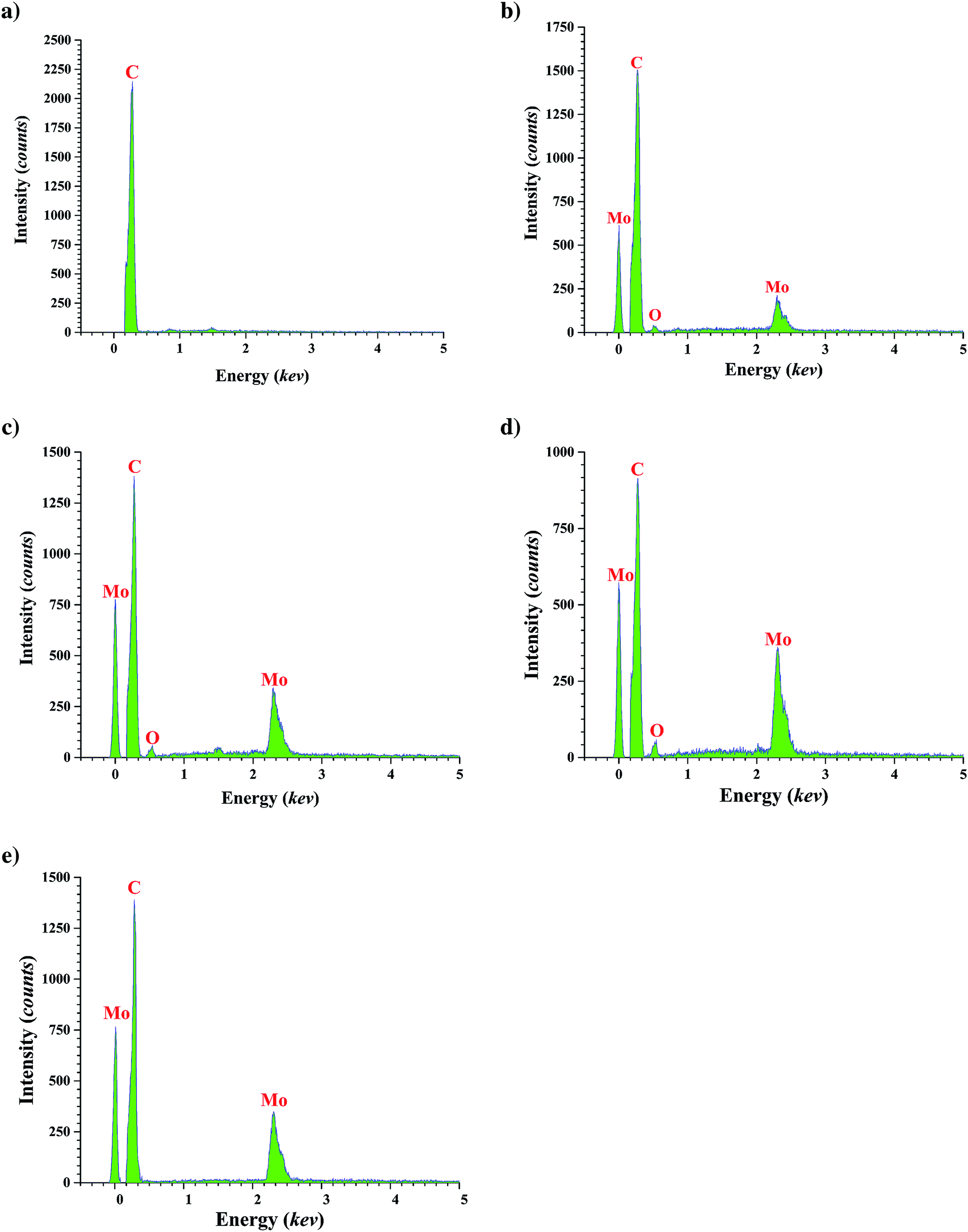 | ||
| Fig. 1 The EDS patterns of FMWCNTs (a); calcined catalyst with loading of 10 wt% molybdenum (b); 20 wt% molybdenum (c); and 30 wt% molybdenum (d); and reduced catalyst with molybdenum loading of 20 wt% (e). | ||
The Brunauer–Emmett–Teller (BET) surface area of each catalyst was measured with a PHSCHINA PHS-1020 apparatus, with N2 as the probe molecule. The X-ray diffraction (XRD) patterns of FMWCNTs and calcined fresh catalyst samples were obtained with a MPD 3000 X-ray diffractometer with a scan window of 0.02°. The average crystallite diameter was determined from the data with the Scherrer equation using the half-widths of peaks.38 Catalyst topography was characterized by field emission scanning electron microscopy (FESEM), which was carried out with a Mira3 microscope. Samples of FMWCNTs with various catalyst loadings were prepared for FESEM by ultrasonic dispersion of the samples in ethanol, and then the suspensions were dropped onto aluminum foil. FESEM imaging was complemented by EDS. TEM analysis was performed with Zeiss-EM10C-100 kV microscope for 20% loading catalyst.
2.4 Catalytic reaction experiments
Catalytic reaction experiments with gas-phase reactants were carried out with a fixed-bed flow reactor at temperatures in the range of 573–673 K and a pressure of 8 bar. Anisole was fed at room temperature into the heated zone of the reactor system, flowing from an HPLC pump at a rate of 0.03 mL min−1. Preheated anisole was vaporized, and the vapor stream merged with the gas feed stream containing N2 as the carrier gas and H2 as a reactant. The N2 and H2 flow rates were each 20 L(NTP) h−1 in all experiments. At the reactor outlet, the product stream flowed out of the heated zone to a condenser, which operated at 275–280 K, and the accumulated liquid samples were collected for periodic analysis. Details of the reactor system are presented in Table 2 and Fig. 2. Fresh catalyst samples (about 0.3 g each) were used for each experiment, and each experiment was typically run for 3 h of continuous operation. The value of the weight hourly space velocity (WHSV) was 6 (g of anisole per g of catalyst per h).| Component of flow reactor system | Property/operating conditions |
|---|---|
| Reactor | 316 L stainless steel; length = 305 mm; inside diameter = 9 mm; outside diameter = 14.5 mm; operating temperature range, 623–723 (±1.5) K; operating pressure range, 8 (±0.1) bar |
| Carrier gas | N2, flow rate, 20 L(NTP) h−1 |
| Reactant gas | H2, flow rate, 20 L(NTP) h−1 |
| Reactant liquid (vaporized in reactor) | Anisole, flow rate range 0.03 (±1%) mL min−1 |
| Catalyst | Mo/CNTs, mass 0.30 g |
 | ||
| Fig. 2 (a) Fixed-bed tubular micro-flow reactor; (b) schematic flow diagram of reactor system. | ||
2.5 Product analysis
The outlet gas stream flowing from the condenser was analyzed online with a gas chromatograph (GC); the main components in the gas phase were H2, N2, and product methane. Liquid product samples were analyzed with a Shimadzu QP 50/50 gas chromatograph-mass spectrometer (GC-MS); compounds were identified by matching mass spectra with those from a Willy library. GC peaks were verified by comparison with those of authentic standards. Liquid products were quantified with a Bruker 450 GC equipped with a flame ionization detector and an OPTIMA 5 Macherey-Nagel capillary column.3 Results
3.1 Catalyst characterization
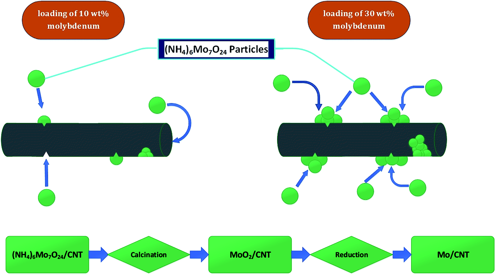 | ||
| Fig. 3 Schematic, qualitative representation of distribution of catalyst particles in CNTs and flow chart of catalyst synthesis procedure. | ||
In summary, the results are consistent with the inference that molybdenum was present in particles on both the interior and exterior surfaces of the CNTs and to some degree blocked pores and access of reactants to the active sites during catalysis. Catalyst performance data summarized below are consistent with the inference.
The XRD patterns of raw FMWCNTs and catalysts with various molybdenum loadings are shown in Fig. 4; the peak at 2θ = 25.6° representing the graphitic plane reflection in carbon nanotubes (002) is evident in the diffraction patterns of all the samples, as are broad peaks at 42.3° representing a graphite plane (100).39
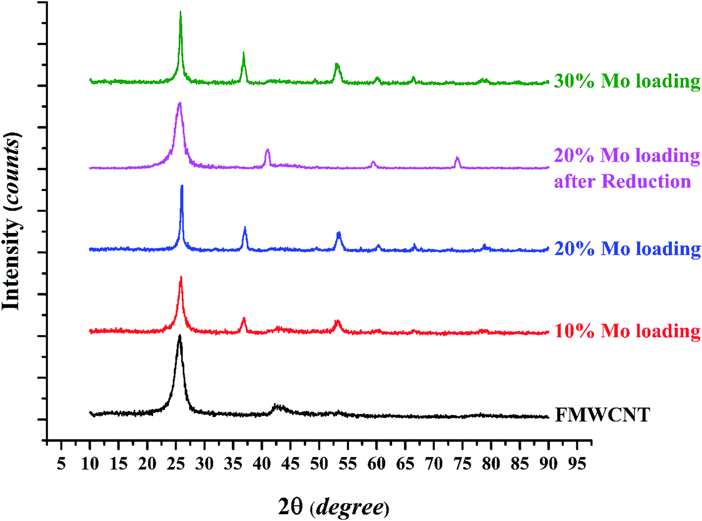 | ||
| Fig. 4 The XRD patterns of raw FMWCNTs and catalysts with various molybdenum loadings. | ||
The diffraction peaks at 37, 53.1, and 60.2° are characteristic of MoO2. In related work, Shang et al.29 reported that for Mo contents up of 8% after a calcination step, MoO2 particles formed as mentioned in EDS analysis after reduction Mo oxide converted to Mo, XRD analysis verify this phenomenon the peak of reduced catalyst shown in Fig. 4, peak at 2θ = 40.8°, 59.5° and 74° are characteristic of molybdenum. The average crystallite sizes determined with the Scherrer equation (Table 1) show that the average crystallite size increased with increasing molybdenum loading, consistent with the results of the BET surface areas and, as shown in the next section, FESEM results.
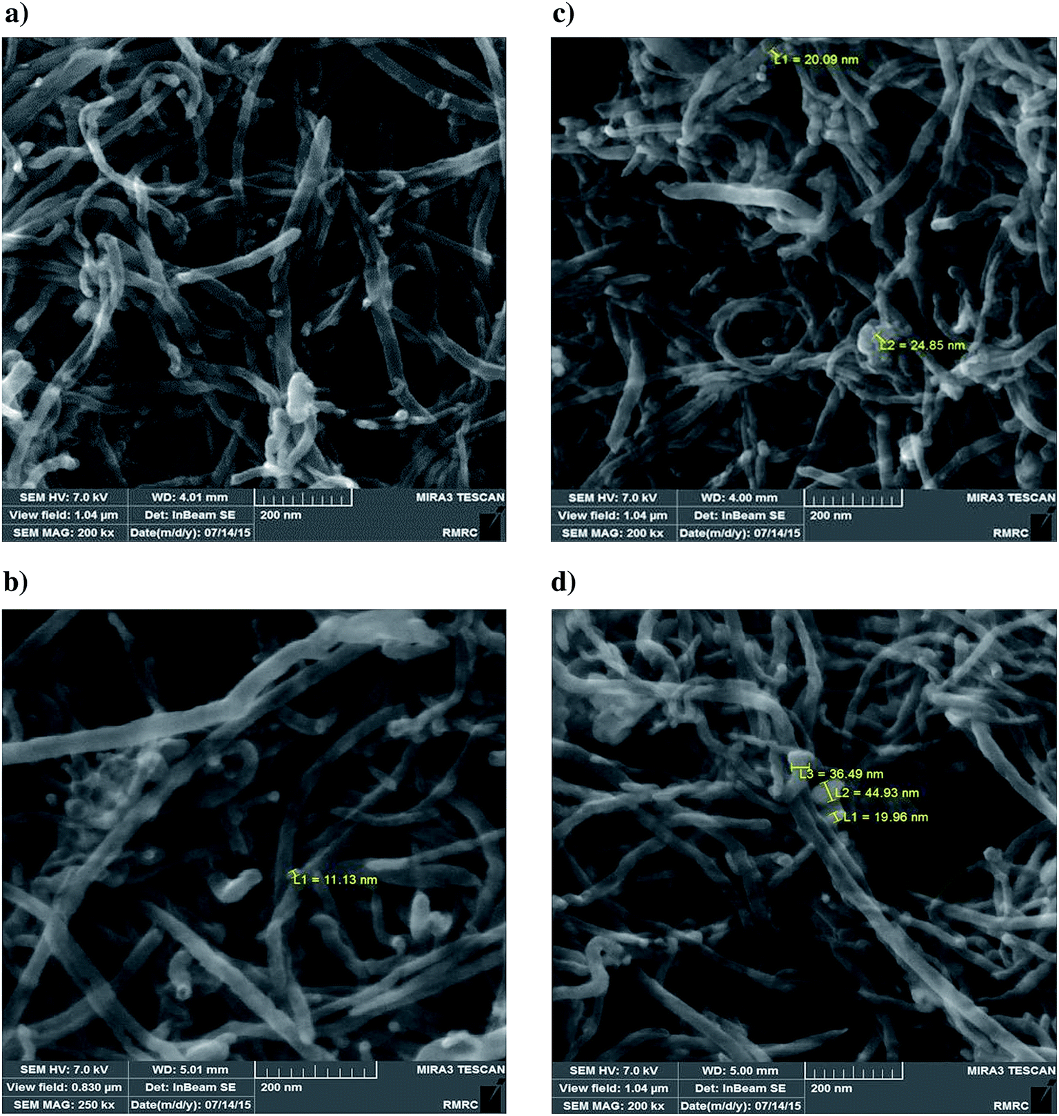 | ||
| Fig. 5 FESEM images of catalysts. (a) FMWCNTs; catalyst with molybdenum loading of 10 wt% (b); 20 wt% (c); 30 wt% (d). | ||
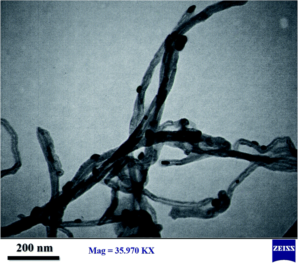 | ||
| Fig. 6 TEM image of catalyst with molybdenum loading of 20 wt%. | ||
In summary, these results are consistent with the surface area/pore volume data and support the inference of pore blocking and the pattern of decreasing molybdenum dispersion with increasing molybdenum content in the catalysts.
3.2 Products of anisole conversion in the presence of H2
The main products of anisole conversion catalyzed by the Mo/CNT samples, identified by GC-MS, were benzene, phenol, 2-methylphenol, 2,6-dimethylphenol, and 2,3,5,6-tetramethylphenol. Trace products that were detected only qualitatively were cyclohexane, toluene, o-xylene, p-xylene, and phenol derivatives such as isomers of methylphenol, dimethylphenol, trimethylphenol, and tetramethylphenol. The GC-MS analyses also demonstrated the formation of small amounts of methane, methanol, and water. Production of benzene associated with the formation of water and methanol confirms that HDO reactions occurred on the catalyst. The observation that phenol was the main product of the conversion shows that hydrogenolysis is a major class of reaction in the anisole conversion. The GC-MS results also lead to the conclusion that alkylation/transalkylation of phenol to give other phenol derivatives took place.3.3 Mass balance closures
Anisole conversions in the catalytic reaction process were calculated on the basis of flow rates of liquid anisole to the reactor and the liquid condensate flowing from the external condenser, as well as the product gas flow rates (although the gas flow rates of anisole and the main products were almost negligible, as determined from the vapor pressures of these compounds at the condenser outlet temperature). Some products, such as methane, were present in the gas phase, and they were accounted for in the mass balance on the basis of the flow rates of the gas-phase products and calculations on the basis of the Antoine vapor pressure correlation for the various products. In the mass balance calculations, the mass flow rate of liquid anisole fed to the reactor in each operating period was determined from the liquid volumetric flow and the density of the anisole (0.995 g mL−1). Furthermore, because the condenser did not drain perfectly, the mass of the condenser and its contents was measured before and after sample collection to account for accumulation in the condenser. Thus, the mass of condensed liquid produced in each operating period of 15 min was measured as the sum of the mass of liquid collected from condenser and that accumulated in the condenser. The mass balance data shown in Table 3 confirm the reliability of the results, with mass balance closures being close to 100%.| Experiment number | Mass balance closure, % | Time on stream, min | Liquid flow rate, mL min−1 | Mass of liquid fed, g | Mass of liquid collected from condenser, g | Mass of product leaving condenser as vapour, g | Approximate mass of liquid remaining in condenser, g |
|---|---|---|---|---|---|---|---|
| 1 | 100 | 180 | 0.03 | 5.37 | 4.22 | 0.15 | 1 |
| 2 | 101.6 | 180 | 0.03 | 5.37 | 4.31 | 0.15 | 1 |
| 3 | 105.4 | 180 | 0.03 | 5.37 | 4.51 | 0.15 | 1 |
| 4 | 98.1 | 180 | 0.03 | 5.37 | 4.12 | 0.15 | 1 |
| 5 | 105 | 180 | 0.03 | 5.37 | 4.49 | 0.15 | 1 |
| 6 | 99.4 | 180 | 0.03 | 5.37 | 4.19 | 0.15 | 1 |
| 7 | 102.6 | 180 | 0.03 | 5.37 | 4.36 | 0.15 | 1 |
| 8 | 98.5 | 180 | 0.03 | 5.37 | 4.14 | 0.15 | 1 |
| 9 | 100.3 | 180 | 0.03 | 5.37 | 4.24 | 0.15 | 1 |
The catalytic reaction experiments were performed for 180 min of continuous operation, with product samples taken every 15 min. Average conversions of anisole from these periods were used to determine the conversions under the various operating conditions.
3.4 Conversion and selectivity as a function of time on stream
The conversion of anisole catalyzed by Mo/CNTs as a function of time on stream (TOS) at various temperatures and molybdenum loadings is shown in Fig. 7, with the data representing 6 h experiments. It is evident that the catalyst performance changed only little during the course of each experiment, and we therefore represent the data as characteristic of initial catalyst performance.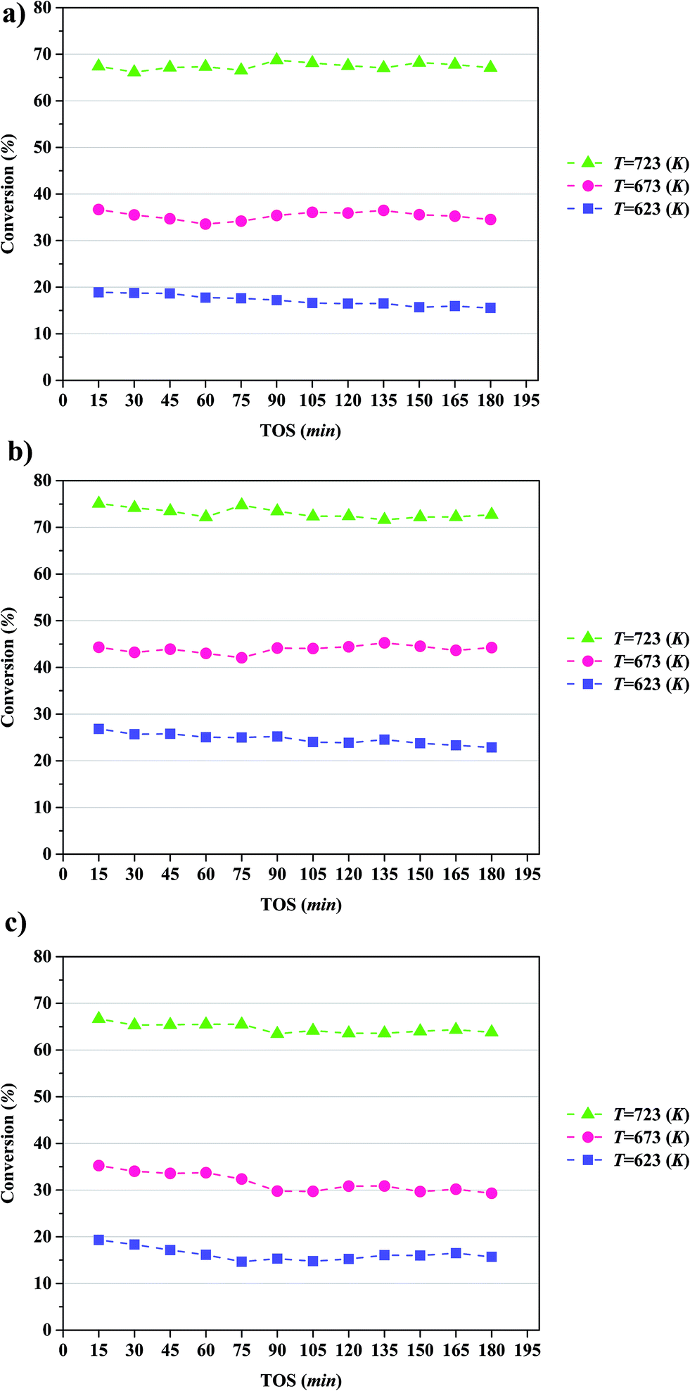 | ||
| Fig. 7 Conversion of anisole catalyzed by Mo/CNT in the presence of H2 in a once-through flow reactor (TOS is time on stream) at the following approximate molybdenum loadings (wt%): (a) 10; (b) 20; (c) 30. | ||
As expected, the anisole conversion increased with increasing temperature. For example, data characterizing the catalyst incorporating 20 wt% molybdenum (Fig. 7b) show that a temperature increase from 623 to 673 K led to an increase in anisole conversion from about 25%, on average, to about 45%, on average. The data also show that increasing the catalyst molybdenum loading from 10 to 20 wt% at 723 K led to an increase in the anisole conversion from about 68 to about 75%, on average, but that a further increase in the molybdenum loading to 30 wt% led to a decreased conversion.
Selectivities to the major products as a function of TOS at a temperature of 723 K, a pressure of 8 bar, a WHSV of 6 (g of anisole per g of catalyst per h), with the catalyst containing and 20 wt% molybdenum, are summarized in Fig. 8. Again, the data indicate that the catalyst performance was essentially stable over the course of the 6 h experiments. The data show that the products formed with greatest selectivity were phenol and benzene; specifically, the selectivity for formation of phenol was found to be greater than that for formation of 2-methylphenol, 2,6-dimethylphenol, and 2,3,5,6-tetramethylphenol. Thus, we infer, as in earlier work with a different catalyst,18,21,22,40,41 that major reaction routes are HDO, hydrogenolysis, alkylation, and transalkylation. Details of the reaction network are presented in the Discussion section.
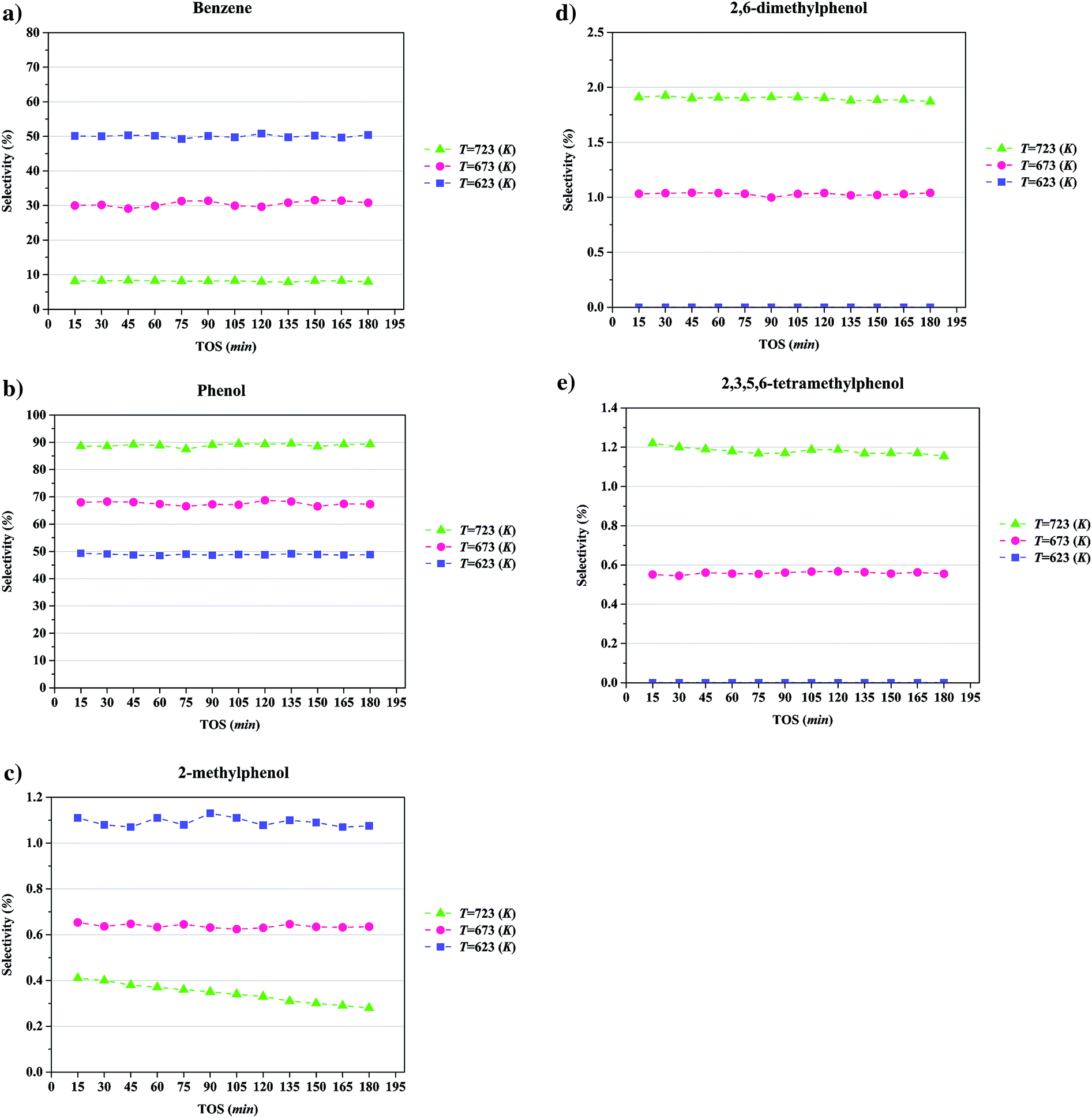 | ||
| Fig. 8 Selectivities in anisole conversion to major products in a once-through flow reactor catalyzed by Mo/CNT at a pressure of 8 bar and WHSV = 6.0 (g of anisole per g of catalyst per h): (a), benzene; (b), phenol; (c), 2-methylphenol; (d), 2,6-dimethylphenol; and (e), 2,3,5,6-tetramethylphenol. | ||
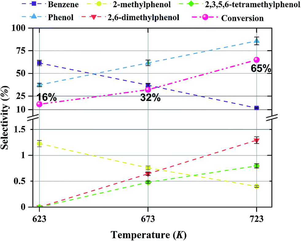
3.5 Effect of temperature and molybdenum loading on selectivity
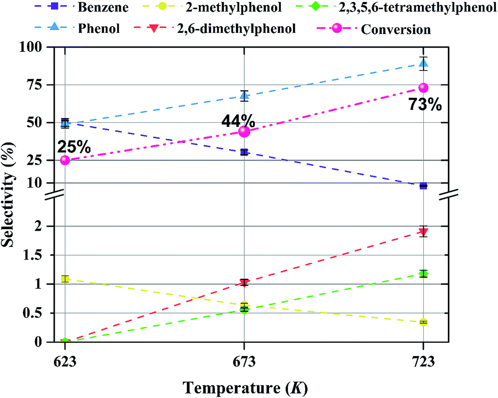
The effect of temperature on the selectivity to the formation of various products during anisole upgrading with catalysts having various molybdenum loadings is shown in Fig. 9–11. The data of Fig. 9 show that the selectivity to benzene as the product of the HDO reaction at 8 bar, WHSV = 6 (g of anisole per g of catalyst per h) with a catalyst containing 10 wt% molybdenum decreased from 60 to 10% as the temperature increased from 623 to 723 K. Increasing the temperature enhanced the selectivity for formation of phenol, 2,6-dimethylphenol, and 2,3,5,6-tetramethylphenol, products of hydrogenolysis and alkylation reactions, but it decreased the selectivity for formation of 2-methylphenol, a transalkylation product.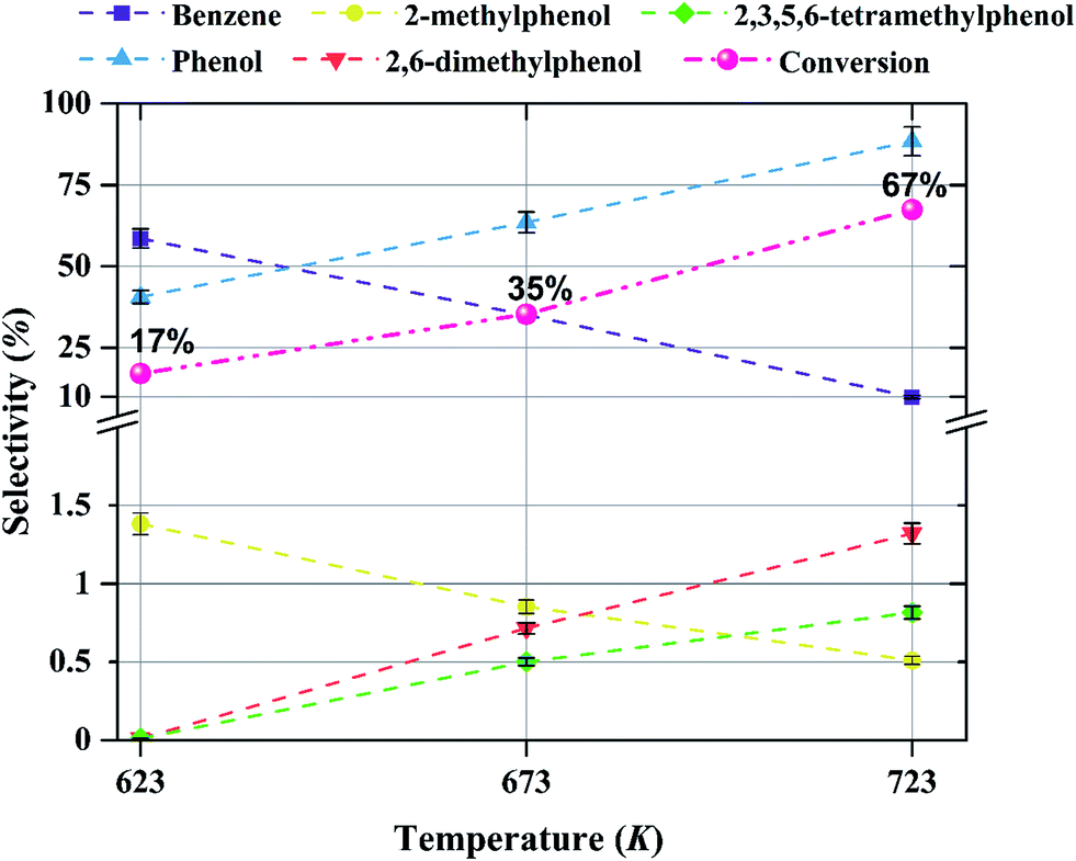 | ||
| Fig. 9 Effect of temperature on selectivity for the formation of various products in anisole upgrading in the presence of H2 catalyzed by Mo/CNTs at 8 bar, with WHSV = 6.0 (g of anisole per g of catalyst per h); the catalyst molybdenum loading was 10 wt%. The conversions are shown next to each point. | ||
 | ||
| Fig. 10 Effect of temperature on selectivity for the formation of various products in anisole upgrading in the presence of H2 catalyzed by Mo/CNTs at 8 bar, with WHSV = 6.0 (g of anisole per g of catalyst per h); the catalyst molybdenum loading was 20 wt%. The conversions are shown next to each point. | ||
 | ||
| Fig. 11 Effect of temperature on selectivity for the formation of various products in anisole upgrading in the presence of H2 catalyzed by Mo/CNTs at 8 bar, with WHSV = 6.0 (g of anisole per g of catalyst per h); the catalyst molybdenum loading was 30 wt%. The conversions are shown next to each point. | ||
4 Discussion
The products observed in this work are similar to those observed in earlier hydroprocessing experiments with anisole as the reactant, but with catalysts different from ours.22,40 Thus, at least to a first approximation, we suggest that the reaction classes are the same as those inferred in the earlier work, specifically including direct bond-breaking of the Caromatic–O bond of anisole, leading to benzene and methanol. Another possible deoxygenation route involves demethylation via scission of the Cmethyl–O bond to give phenol, which may be followed by conversion of the phenol to benzene by hydrogenolysis of the Caromatic–O bond. Because the second route is kinetically dominant, we suggest that the scission of the Cmethyl–O bond is faster than the scission of the Caromatic–O bond. The selectivity data presented in Fig. 8a, in combination with the aforementioned literature, indicate that other kinetically significant reactions include hydrogenolysis of the aromatic carbon–oxygen bond to form phenol as a main product, followed by phenol conversion to phenol derivatives via alkylation and transalkylation reactions.The data indicate that selectivity for oxygen removal is favored by operation at lower temperatures; the trends were observed for our catalysts with various molybdenum loadings (Fig. 10 and 11). The data also show that for the catalysts containing 10 and 20 wt% molybdenum, increasing the molybdenum loading leads to an increase in the hydrogenolysis selectivity more than the HDO selectivity. For example, at 623 K, the selectivity to benzene decreases from approximately 60% to approximately 50% as the catalyst molybdenum content increases from 10 to 20 wt%, whereas the selectivity to phenol increases from approximately 40% to approximately 50%.
With bifunctional catalysts such as molybdenum supported on γ-Al2O3, some reactions, including alkylation, are catalyzed by the acidic support. But CNTs are more weakly acidic than oxides such as γ-Al2O3 and TiO2, and therefore the selectivity to phenol derivatives with CNT-supported molybdenum catalysts was expected to be less than was observed with these other supports. The observations bear out this expectation, and the oxygen removal is attributed largely to the role of the molybdenum-containing species activating H2 for HDO reactions.1,9,17,29,34,42–44 Our data are consistent with the premise that the molybdenum species are active for both HDO and hydrogenolysis reactions, and we thus consider it likely that these species catalyze HDO to form benzene, which is kinetically a highly significant reaction under our conditions. On the basis of these inferences, we suggest a simplified, qualitative, and approximate reaction network for anisole hydroprocessing on Mo/CNTs, as shown in Fig. 12; we emphasize that the alkylation reactions are minor in comparison with the others shown.
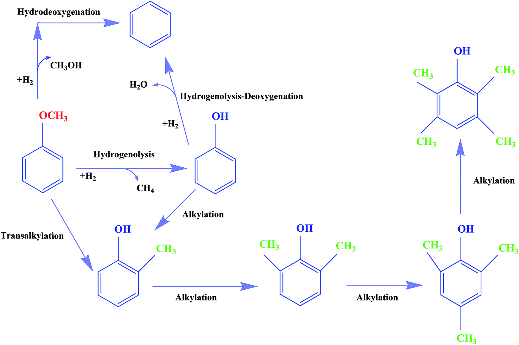 | ||
| Fig. 12 Approximate, qualitative reaction network for the conversion of anisole in the presence of H2 catalyzed by Mo/CNTs at 623–723 K, 8 bar, and WHSV = 6.0 (g of anisole per g of catalyst per h). | ||
To check whether the catalyst performance data were influenced by the rates of external mass transport, we varied the feed flow rate and catalyst mass with WHSV held constant at 6.0 (g of anisole per g of catalyst per h). As shown in Table 4, the anisole conversions at constant WHSV and different catalyst masses were found to be approximately the same, consistent with the inference that external mass transfer did not influence the reaction rates.
| Anisole flow rate (mL min−1) | Mass of catalyst (g) | Anisole conversion (%) |
|---|---|---|
| 0.03 | 0.3 | 44.5 |
| 0.06 | 0.6 | 45.1 |
| 0.1 | 1 | 44.2 |
| 0.15 | 1.5 | 43.8 |
| 0.2 | 2 | 43.5 |
The possible importance of mass transport limitations within the carbon nanotubes is, however, considered to be significant, and this point is developed below.
The physical characterization data show various degrees of dispersion of the molybdenum, depending strongly on the loading, and they indicate that particulate molybdenum-containing species are substantially present within the CNTs as well as on their outer surfaces. These catalytic species confined within the nanotubes would be expected to interact strongly with them, suggesting that they might be resistant to sintering and thus contribute to relatively long catalyst lifetimes; we posit that this suggestion is worthy of investigation. Encapsulation of the catalytic species within the narrow nanotubes might also affect their electronic properties and thereby their catalytic properties, and we suggest that this point is also worthy of investigation.
On the other hand, these encapsulated particles would be expected to block the small pores and thereby lead to small micro-effectiveness factors, such that the catalyst utilization might be markedly less than that in comparable catalysts on mesoporous supports. These issues remain to be resolved. A comparison of the activities of the catalysts reported here with those of other molybdenum-containing hydroprocessing catalysts leads to the inferences that Mo/CNT catalysts offer attractive activities and HDO selectivities.34,45
5 Conclusions
Mo/CNT catalysts were evaluated for the catalytic hydroprocessing of anisole as a model compound representing lignin-derived bio-oils. The catalyst performance data indicate that benzene, phenol, 2-methylphenol, 2,6-dimethylphenol, and 2,3,5,6-tetramethylphenol are the main products of anisole conversion in the presence of H2. The important reaction classes are HDO and hydrogenolysis, accompanied by transalkylation and alkylation reactions. Higher temperatures favor the selectivity for hydrogenolysis reactions.References
- M. Saidi, F. Samimi, D. Karimipourfard, T. Nimmanwudipong, B. C. Gates and M. R. Rahimpour, Energy Environ. Sci., 2014, 7, 103–129 CAS.
- W.-S. Lee, Z. Wang, R. J. Wu and A. Bhan, J. Catal., 2014, 319, 44–53 CrossRef CAS.
- E. Furimsky, J. Mikhlin, D. Jones, T. Adley and H. Baikowitz, Can. J. Chem. Eng., 1986, 64, 982–985 CrossRef CAS.
- S. T. Srinivas, A. K. Dalai and N. N. Bakhshi, Can. J. Chem. Eng., 2000, 78, 343–354 CrossRef CAS.
- P. J. De Wild, W. J. Huijgen and R. J. Gosselink, Biofuels, Bioprod. Biorefin., 2014, 8, 645–657 CrossRef CAS.
- A. Demirbaş, Energy Convers. Manage., 2001, 42, 1357–1378 CrossRef.
- E. Furimsky, Appl. Catal., A, 2000, 199, 147–190 CrossRef CAS.
- R. Venderbosch and W. Prins, Biofuels, Bioprod. Biorefin., 2010, 4, 178–208 CrossRef CAS.
- S. Czernik and A. Bridgwater, Energy Fuels, 2004, 18, 590–598 CrossRef CAS.
- A. Oasmaa and S. Czernik, Energy Fuels, 1999, 13, 914–921 CrossRef CAS.
- X. Zhang, T. Wang, L. Ma, Q. Zhang, Y. Yu and Q. Liu, Catal. Commun., 2013, 33, 15–19 CrossRef CAS.
- A. Gutierrez, R. Kaila, M. Honkela, R. Slioor and A. Krause, Catal. Today, 2009, 147, 239–246 CrossRef CAS.
- M. Á. González-Borja and D. E. Resasco, Energy Fuels, 2011, 25, 4155–4162 CrossRef.
- M. Bykova, D. Y. Ermakov, V. Kaichev, O. Bulavchenko, A. Saraev, M. Y. Lebedev and V. Yakovlev, Appl. Catal., B, 2012, 113, 296–307 CrossRef.
- O. Şenol, E.-M. Ryymin, T.-R. Viljava and A. Krause, J. Mol. Catal. A: Chem., 2007, 277, 107–112 CrossRef.
- A. Bridgwater and M. Cottam, Energy Fuels, 1992, 6, 113–120 CrossRef CAS.
- T. Nimmanwudipong, R. C. Runnebaum, K. Tay, D. E. Block and B. C. Gates, Catal. Lett., 2011, 141, 1072–1078 CrossRef CAS.
- R. C. Runnebaum, R. J. Lobo-Lapidus, T. Nimmanwudipong, D. E. Block and B. C. Gates, Energy Fuels, 2011, 25, 4776–4785 CrossRef CAS.
- T. Nimmanwudipong, R. C. Runnebaum, D. E. Block and B. C. Gates, Catal. Lett., 2011, 141, 779–783 CrossRef CAS.
- M. Saidi, P. Rostami, M. R. Rahimpour, B. C. Gates and S. Raeissi, Energy Fuels, 2015, 29, 191–199 CrossRef CAS.
- M. Saidi, P. Rostami, M. R. Rahimpour, B. C. Gates and S. Raeissi, Energy Fuels, 2014, 29, 191–199 CrossRef.
- M. Saidi, P. Rostami, H. R. Rahimpour, M. A. Roshanfekr Fallah, M. R. Rahimpour, B. C. Gates and S. Raeissi, Energy Fuels, 2015, 29, 4990–4997 CrossRef CAS.
- T. Nimmanwudipong, R. C. Runnebaum, D. E. Block and B. C. Gates, Energy Fuels, 2011, 25, 3417–3427 CrossRef CAS.
- W. Wang, Y. Yang, H. Luo, H. Peng and F. Wang, Ind. Eng. Chem. Res., 2011, 50, 10936–10942 CrossRef CAS.
- C. Loricera, B. Pawelec, A. Infantes-Molina, M. Álvarez-Galván, R. Huirache-Acuna, R. Nava and J. Fierro, Catal. Today, 2011, 172, 103–110 CrossRef CAS.
- I. Ghampson, C. Sepúlveda, R. Garcia, B. Frederick, M. Wheeler, N. Escalona and W. DeSisto, Appl. Catal., A, 2012, 413, 78–84 CrossRef.
- E.-M. Ryymin, M. L. Honkela, T.-R. Viljava and A. O. I. Krause, Appl. Catal., A, 2010, 389, 114–121 CrossRef CAS.
- V. M. Whiffen and K. J. Smith, Energy Fuels, 2010, 24, 4728–4737 CrossRef CAS.
- H. Shang, C. Liu, Y. Xu, J. Qiu and F. Wei, Fuel Process. Technol., 2007, 88, 117–123 CrossRef CAS.
- Y. Yan, J. Miao, Z. Yang, F.-X. Xiao, H. B. Yang, B. Liu and Y. Yang, Chem. Soc. Rev., 2015, 44, 3295–3346 RSC.
- P. Azadi, R. Farnood and E. Meier, J. Phys. Chem. A, 2009, 114, 3962–3968 CrossRef PubMed.
- C. Li, Z. Shao, M. Pang, C. T. Williams, X. Zhang and C. Liang, Ind. Eng. Chem. Res., 2012, 51, 4934–4941 CrossRef CAS.
- M. Trépanier, A. Tavasoli, S. Anahid and A. K. Dalai, Iran. J. Chem. Chem. Eng., 2011, 30, 37–47 Search PubMed.
- T. Prasomsri, M. Shetty, K. Murugappan and Y. Román-Leshkov, Energy Environ. Sci., 2014, 7, 2660–2669 CAS.
- E. Soghrati, M. Kazemeini, A. Rashidi and K. J. Jozani, J. Taiwan Inst. Chem. Eng., 2014, 45, 887–895 CrossRef CAS.
- R. Ding, Y. Wu, Y. Chen, J. Liang, J. Liu and M. Yang, Chem. Eng. Sci., 2015, 135, 517–525 CrossRef CAS.
- W. Chen, Z. Luo, C. Yu, Y. Yang, G. Li and J. Zhang, Fuel Process. Technol., 2014, 126, 420–428 CrossRef CAS.
- A. Fazil and R. Chetty, Electroanalysis, 2014, 26, 2380–2387 CrossRef CAS.
- A. Kim, S. Lim, D.-H. Peck, S.-K. Kim, B. Lee and D. Jung, Nanomaterials, 2012, 2, 206–216 CrossRef CAS.
- H. R. Rahimpour, M. Saidi, P. Rostami, B. C. Gates and M. R. Rahimpour, Int. J. Chem. Kinet., 2016, 48, 702–713 CrossRef CAS.
- M. Saidi, H. R. Rahimpour, B. Rahzani, P. Rostami, B. C. Gates and M. R. Rahimpour, Can. J. Chem. Eng., 2016, 94, 1524–1532 CrossRef CAS.
- R. Sharma and N. Bakhshi, Can. J. Chem. Eng., 1991, 69, 1071–1081 CrossRef CAS.
- A. Centeno, E. Laurent and B. Delmon, J. Catal., 1995, 154, 288–298 CrossRef CAS.
- V. M. Whiffen, K. J. Smith and S. K. Straus, Appl. Catal., A, 2012, 419, 111–125 CrossRef.
- M. Huuska, Polyhedron, 1986, 5, 233–236 CrossRef CAS.
| This journal is © The Royal Society of Chemistry 2017 |