
 Open Access Article
 This Open Access Article is licensed under a
 Creative Commons Attribution 3.0 Unported Licence
A novel microfluidic device to model the human proximal tubule and glomerulus†
Courtney M.
Sakolish
and
Gretchen J.
Mahler
 *
*
Department of Biomedical Engineering, Binghamton University, PO Box 6000, Binghamton, NY 13902, USA. E-mail: gmahler@binghamton.edu
First published on 16th January 2017
Abstract
We have developed a re-usable multi-layer microfluidic device to model the human kidney that incorporates a porous growth substrate, physiological fluid flow, and the passive filtration of the glomerulus. The target cell line in this project is HK-2, immortalized human kidney proximal tubule cells. Cells were exposed to a shear stress of 0.8 dyne cm−2 within the device and monitored for protein expression, cytoskeletal reorganization, and increased molecular transport. Additionally, an endothelial cell-seeded glomerular filter was added to allow for more realistic “primary urine” within these devices. The results of this research suggest that cells grown within this microfluidic device exhibit more in vivo-like behaviour than those grown using traditional culturing methods, and that the filtration of serum proteins by the glomerulus is necessary for healthy cell function. The addition of this glomerulus-mimic to the device provides the first in vitro model of passive glomerular filtration coupled with the proximal tubule.
Introduction
The early stages of drug development involve the use of animal testing for in vivo data. This process is expensive, lengthy and sometimes controversial.1,2 In addition to these issues, there remains the question as to whether the data obtained from these animal tests can be extrapolated to human systems. In 2004, it was reported by the US Food and Drug Administration that of every 100 drugs that successfully passed animal trials, 92 fail in the subsequent human trials.3 Additionally, of every 10![[thin space (1/6-em)]](https://www.rsc.org/images/entities/char_2009.gif) 000 compounds going through research and development, 5 to 10 will progress to clinical trials and only 1 actually receives FDA approval.4 This low success rate is primarily due to toxicity and an unforeseen lack of efficacy when the drug is applied to human systems. To better direct resources toward more promising candidates and prevent late stage clinical failure, an “organ-on-a-chip” device could be utilized to accurately model human systems in a compact, efficient microfluidic device.
000 compounds going through research and development, 5 to 10 will progress to clinical trials and only 1 actually receives FDA approval.4 This low success rate is primarily due to toxicity and an unforeseen lack of efficacy when the drug is applied to human systems. To better direct resources toward more promising candidates and prevent late stage clinical failure, an “organ-on-a-chip” device could be utilized to accurately model human systems in a compact, efficient microfluidic device.
The kidney is primarily responsible for the removal of compounds from the bloodstream and their subsequent excretion from the body.5 Understanding the functions of the kidney is essential in the research and development of new compounds to ensure long residence time in the body and the proper removal of these compounds once they have served their function within the system. Kidney toxicity is one of the most widely reported adverse effects during drug development, and it can only be detected late into the drug development process.6,7 Through the incorporation of human kidney cells into an optimized microfluidic device, it will be possible to study and understand these adverse toxic effects before they appear in human clinical trials. Additionally, the reuptake mechanisms of the kidney have only recently been investigated, so a device that closely mimics in vivo behaviors could provide some insight into this issue as well. Recently, fluidic culturing of renal cells has provided some interesting insight into the functions and behaviors of these cells in vivo. For example, the works of Jang et al. have demonstrated the culture of renal collecting duct cells within PDMS (polydimethyl siloxane) multi-channel devices with a fluidic top channel, and static bottom reservoir in various works.8,9 Through the addition of physiologically relevant fluid shear stress (FSS), these works demonstrated the enhanced cell polarization, cytoskeletal reorganization, increased barrier function, and trafficking that is observed in vivo. Additionally, Raghavan et al. demonstrated that shear stress affects tubule cell transport and signaling, necessitating fluidic culturing for accurate recapitulation of in vivo cell behaviours.10 The works of Sciancalepore et al. further demonstrated the use of microfluidic growth platforms to recapitulate realistic cell behaviors through the use of adult renal progenitor cells, which were found to have high differentiation potentials, as well as a great capacity for injured renal cell regeneration.11 These multi-channel devices also focused on the need for a porous membrane cell growth surface. Frohlich et al. further demonstrated the fabrication of topographically patterned porous membranes for applications in the modelling of renal reabsorptive barriers within these biomimetic devices, and found that HK-2 cells aligned in the direction of the ridge/groove topography of the fabricated membranes, indicating the presence of mechanical influences on cell response.12 These works laid down the foundation for the device design presented in this paper, however these previous models do not account for glomerular filtration of the “primary urine” that would be found in the interstitial area of the renal tubule.
Renal filtration consists of both passive and active filtration. The glomerulus acts as a passive filtration barrier, preventing larger molecular weight serum proteins from entering the nephron so that they can continue to circulate in the blood stream. Filtrate that is able to pass through this selective barrier (8 nm pore) enters the nephron, where selective active transport takes place. In this study, an endothelial cell-seeded glomerular filter (HUVEC), and proximal tubule (HK-2) cells grown in a multi-layered fluidic platform are used to model the behavior of the human glomerulus and proximal tubule. This will be the first report of a microfluidic kidney model that incorporates passive glomerular filtration. HK-2 is a line of immortalized epithelial cells of human origin, from the proximal tubule region of the nephron, located in the cortex.13 Its main function is the reuptake of salts, sugars, water, and small proteins from urine precursor so that these useful compounds are not excreted. This reabsorption is achieved through both active (megalin14 and cubilin15 receptors), and passive, pressure driven transport. During this absorption process, urine becomes highly concentrated, allowing for toxicity of compounds within this concentrate to emerge. Due to this consequence, the majority of toxicity cases (90%) occur within the proximal tubule and glomerular regions of the kidney.16 Additionally, the majority of chronic kidney diseases originate in the glomerulus following compromised barrier function. Despite this, the current understanding of glomerular functions and pathologies are limited due to a lack of in vitro models of glomerular filtration. This high toxicity, in addition to the percentage of total reuptake (∼70%) that occurs in the proximal tubule makes it an attractive target for modelling studies.17
Experimental
1. Materials and reagents
Materials for cell culture were obtained from the following suppliers: HK-2 cells (ATCC), Dulbecco's modified Eagle's medium: Ham's nutrient mixture F12, 1:1 mix (DMEM/F-12), phenol red-free DMEM/F12, keratinocyte serum-free medium (SFM), fluorescein–phalloidin (Life Technologies, CA); human fibronectin (BD Biosciences, NJ); cell culture flasks and 6 or 24 well Transwells® (polycarbonate 0.4 μm pore size) (Corning, NY); mouse anti-occludin, rabbit anti-β-catenin, Alexa fluor 488/568 anti-mouse/rabbit, FITC-BSA, FITC-ovalbumin, Fluoreporter labelling kit (Invitrogen, CA); rabbit anti-caveolin-1 (Spring Bioscience, CA); rabbit anti-ZO-1, mouse anti-clathrin (abcam, MA); L-glutamic acid, glycylglycine, Fast Blue BBS, Trizma base, EIPA, nystatin, 10 μm fluorescent microbeads, 100 nm fluorescent microbeads (Sigma-Aldrich, MO); NGAL/Lipocalin-2 duoSet ELISA (R&D Systems, MN), and fibronectin ELISA (Thermo-Fisher, MA).
Materials for device fabrication were obtained from the following suppliers: polydimethylsiloxane (PDMS) (Dow Corning, MI); 0.4 μm pore polycarbonate membranes (Whatman, Maidstone, UK); Gold-Seal™ cover-glass slides (Thermo-scientific, MA); 100 mm silicon wafers (University Wafer); SU-8 2000 (MicroChem, MA); Sigmacote (Sigma-Aldrich, MO); polycarbonate sheets (Bayer, Leverkusen, DE); duro transparent silicone sheets (McMaster-Carr, IL); 0.25 mm/0.51 mm diameter biocompatible tubing (Cole-Parmer, CT); 1–200 μL gel loading pipet tips (FisherBrand, Loughborough, UK); Stripwell plates (Corning, NY); peristaltic pump (Watson-Marlow, MA); printing of transparency masks (Infinite Graphics, MN).
2. Device fabrication
Single channel devices were created through photolithography and the cast molding of PDMS in a clean-room environment. Silicon wafers were spin coated with SU-8 photoresist (50 μm thickness) and selectively polymerized through the use of a contact aligner with customized transparencies (6.5 second UV exposure). Once the excess monomer was rinsed from the wafer, it was silanized with Sigmacote® to allow for easier PDMS removal. PDMS (Sylgard® 184 elastomer kit) elastomer base was mixed with a curing agent at a 10:1 ratio and placed under vacuum for 2 hours to remove any trapped gas. Elastomer was poured over the wafer at a 1/4-inch thickness, and cured for 1 hour at 85 °C. After curing, the PDMS layer was removed from the silicon master, and holes were punched for inlets and outlets using an 8G needle. Glass coverslips were soaked in a 50% ethanol solution under sonication, then the PDMS and coverslips were plasma cleaned to increase binding. After cleaning, the pieces were permanently bonded. The final channel dimensions were 30 mm × 15 mm × 50 μm height (Fig. 1A).
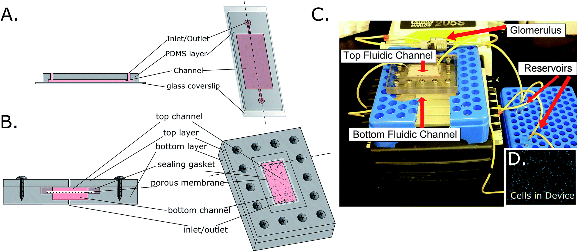 | ||
| Fig. 1 Microfluidic device designs for single channel (A) and multi-channel (B) devices. (C) The final device assembly with notable features marked. (D) Calcein-AM live staining image of cell-seeded membrane removed from the microfluidic device. | ||
Multi-channel devices were created through CNC milling of polycarbonate (McMaster-Carr) by Glenn Swan (School of Chemical and Biomolecular Engineering, Cornell University). The final fluidic channel dimensions were 30 mm × 15 mm × 50 μm. Tapered holes were created for inlets and outlets in both the top and bottom layers, with an initial diameter of 740 μm then decreasing to 610 μm after a 3 mm step toward the center of the device. This tapering allowed for the locking of gel loading pipet tips (FisherBrand) into the inlets and outlets, which could then be connected to tubing (Cole-Parmer) on a recirculating peristaltic pump (Watson-Marlow). Holes were milled for screws that join the top and bottom layers of this device. A step was created between the two channels to hold a membrane (polycarbonate, 0.4 μm pore, Whatman) in place between silicone gaskets that seal the device, effectively separating the top and bottom channels. Wells from a 96-well Stripwell plate (Costar) were used as media reservoirs. The channel dimensions for the multi-channel devices were designed to be the same as with the single-channel device, the only difference being the actual number of channels (Fig. 1B).
In addition to the microfluidic devices which serve as a growth platform to cells, a small chamber was added in circuit to act as a passive filtration barrier, similar to the way that the glomerulus in the body functions. This was achieved through the use of a stainless steel filter housing (14 mm diameter, Avdantec MFS, Inc) that was fitted with either an 8 nm (Sartorius Stedim Biotech) or 30 nm (Sterlitech) pore size PES filter that had been coated with a realistic EBM (epithelial basal membrane) and GBM (glomerular basal membrane), as well as HUVEC cells (Fig. 4E). Medium would flow through this chamber prior to entering the proximal tubule, top fluidic channel, removing large molecular weight particles, creating a more realistic “primary urine” solution (Fig. 1C). This filter however, was not added to the bottom fluidic channel, which acted as a “bloodstream” channel. The full schematic of the device assembly is shown in ESI Fig. 1.†
3. Cell culture
HK-2 cells were seeded at a density of 100000 cells per cm2 onto fibronectin-coated (8 μg cm−2) Transwells or device membranes in DMEM/F12 medium. HUVECs were seeded at 100000 cells per cm2 onto fibronectin coated 8 or 30 nm PES filters. A realistic GBM was created through layering of collagen (I) and heparin sulfate ECM coatings. Cells were grown overnight (37 °C, 5% CO2) prior to these experiments unless stated otherwise.
Growth curves were performed over a period of 6 days in 6-well plates using either SFM or DMEM/F12 medium to determine optimal growth medium for HK-2 cultures. Each day, cells were trypsinized and a cell count was obtained using a hemocytometer.
Transepithelial electrical resistance (TER) of HK-2 cells was measured using an EVOM2 epithelial voltohmmeter (WPI Inc., FL) over a period of 6 days in either SFM or DMEM/F12 to determine the maximum barrier properties for the monolayers.
Gamma-glutamyl transpeptidase (GGT) assays were performed on the HK-2 cell line at day 2 to determine enzymatic activity of the cell line in SFM vs. DMEM/F12 media following the procedure described in the work of Rutenburg et al.18 Cells were seeded at a density of 40000 cells per cm2 on glass slides coated with fibronectin (8 μg cm−2), and allowed to grow for 2 days prior to staining. Medium was removed from chambers and cells were rinsed with PBS. Slides were flash-frozen in a mixture of isopentane and dry ice, followed by an incubation in either a gamma-glutamyl-4-methoxy-2-naphthylamide (GMNA) solution (1 mL GMNA (2.5 mg mL−1), 10 mg glycylglycine, 10 mg Fast Blue BBS, 5 mL Tris buffer (0.1 M, pH 7.4), and 14 mL NaCl (0.85%)) or a control solution (same as GMNA solution, but lacking GMNA) for 2 minutes. After this short incubation, slides were rinsed with distilled water, dried and mounted using Permount. Using a phase contrast microscope and image processing software, ImageJ (Rasband, W.S., ImageJ, U. S. National Institutes of Health, Bethesda, Maryland, USA, http://imagej.nih.gov/ij/, 1997–2015), the degree of GGT activity was quantified through image analysis and quantification of positive colorimetric staining against control slides.
4. Protein transport
HK-2 cells were seeded at 100000 cells per cm2 and grown to confluence over 2 days on Transwells® or within devices in DMEM/F12 prior to transport studies. BSA- or ovalbumin-Alexa Fluor® 488 conjugate was introduced to the top chamber at a concentration of 0.4 mg mL−1 and pH of 6.0 or 7.0 in phenol red-free and serum free DMEM/F12. Medium was added to the bottom chamber at a pH of 7.0. Plates were rocked at 6 rpm for 2 hours at either 37 °C or 4 °C (to determine differences between active and passive transport) and samples were taken from the bottom well at time points of 15, 30, 45, 60, 90 and 120 minutes. In the case of devices, cells were exposed to the protein solution at a shear stress of 0.8 dyne cm−2 over the same time period. Aliquots were drawn from reservoirs or the bottom wells of Transwells® (for fluidic and static experiments, respectively) at the 2 hour endpoint. Samples were placed in a black 96 well assay plate and fluorescence values over time were determined using a Synergy 2 fluorescent plate reader (BioTek) with a 485/528 excitation/emission filter.
5. Chemical inhibition of active transporters
To confirm the presence and behavior of the two main active transport mechanisms (caveolae and clathrin-coated pits) in HK-2 cells, inhibitors of these transport mechanisms19,20 were added to cell culture medium for a period of 2 hours prior to IHC staining. Cells were grown on Transwell® supports for 48 hours, then nystatin (25 mM, 0.5% DMSO vehicle) was added as an inhibitor of caveolin-1 and EIPA (5-(N-ethyl-N-isopropyl)amiloride) (100 mM) as a clathrin inhibitor. Immunohistochemistry staining was performed on control cell slides and inhibited cell slides to qualitatively determine differences in protein expression.6. Immunohistochemistry
HK-2 cells were grown for 2 days in DMEM/F12 on Transwells® or within a device (0.1 or 0.8 dyne cm−2) then fixed with 4% paraformaldehyde for 50 minutes, and washed 3 times with PBS. After washing, cells were permeabilized with 0.1% Triton X-100 for 5 minutes, and washed again with PBS. Through the remainder of the procedure, cells were rocked at a speed of 10 rpm. Samples were incubated for 1 hour at room temperature in a 5% BSA blocking solution followed by a 2 hour incubation at 37 °C in a 1:100 solution of primary antibodies for caveolin-1, occludin, ZO-1, clathrin or β-catenin. Cells were washed with PBS followed by incubation in the dark with a 1:100 solution of secondary antibody with Alexa Fluor® 488 or 568 conjugate. Samples were then rinsed 2 times with PBS followed by a 30 minute dark incubation in a solution of 1:1000 DRAQ5 far red nuclear stain, and a 1:100 dilution of fluorescein–phalloidin when applicable. After one final rinse with 18 MΩ water, membrane inserts were removed and mounted on glass slides. Images were taken with a Leica TCS SP5 laser scanning confocal microscope.
7. Shear stress duration studies
HK-2 cells were cultured on membranes or Transwells® (static control) at a density of 100000 cells per cm2 as previously described. After a growth period of 24 hours, membranes were placed inside the multi-layer microfluidic device and exposed to a shear stress of 0.8 dyne cm−2 for 1, 5, 24 or 48 hours. Static control cells in Transwells® were allowed to grow undisturbed for 48 hours. After this exposure period, control and experimental cells were fixed in a 4% PFA solution and fluorescently labelled for clathrin and β-catenin. Membranes were then imaged using a Leica TCS SP5 confocal microscope, and percentage of positive staining per field over time was quantified through the use of ImageJ and the “Threshold Color” plug-in.
8. Glomerular protein filtration
To test the filtration of proteins through the glomerulus attachment, the entire top channel of the microfluidic system (glomerulus attachment and proximal tubule chamber) was filled with a 0.1 mg mL−1 solution of FITC-BSA in serum free, phenol red free DMEM/F12. The bottom, “bloodstream” channel was filled with the serum free DMEM/F12, without any tagged protein. Flow was introduced at 0.4 dyne cm−2 (8 nm filter) which was the maximum fluid flow the filter could withstand. Samples were drawn from the top and bottom reservoirs at 0, 15, 30, 45, 60 and 120 minutes and placed in a black, 96-well plate. The protein concentration of samples was determined through the use of a plate reader against a standard curve.9. Effect of low shear on clathrin expression
To determine the effect of low shear stress (caused by the addition of the 8 nm glomerulus filter) on clathrin expression, devices were run under 3 conditions: low shear (0.1 dyne) with glomerulus, low shear without glomerulus, and intermediate shear (0.8 dyne) without glomerulus. Cells were seeded onto fibronectin-coated membranes at a density of 100000 cells per cm2 and placed within the device. Flow was induced for a 2 hour period, then membranes were removed and fixed with a 4% PFA solution. After cells were fixed, IHC staining for clathrin and DNA was performed. Images from three fields on the membrane were taken with a Leica TCS confocal microscope and protein expression was quantified though the use of the “Color Threshold” plug-in in ImageJ.
10. NGAL and fibronectin excretion
Cells were grown as previously described in either static or fluidic (0.8 dyne cm−2) conditions for 24 hours, and then cell culture supernatant was collected after this culture period. Additionally, fluidic devices (0.4 dyne cm−2) were run for 5 hours with or without the glomerulus filtration attachment on the top fluidic channel. After this growth period, cell culture supernatant was collected. To determine differences in the release of these cell distress markers (NGAL and fibronectin) between static culture and devices with and without the ultrafiltration of proteins by the glomerulus attachment, commercially available ELISA kits for NGAL and fibronectin were utilized following manufacturers protocols. Results of this colorimetric assay were determined through the use of a Synergy 2 plate reader.11. Alkaline phosphatase expression
To determine the expression of ALP (alkaline phosphatase) in cultures that were grown either in static or fluidic (0.8 dyne cm−2) conditions, and in glomerulus or non-glomerulus devices (both at 0.4 dyne cm−2), cells were grown in DMEM/F12 under these various conditions for 5 hours, and cell lysate was collected through ultrasonication. After lysate was collected, the Bradford assay was performed to determine total protein concentration in lysate samples. 250 μL of Bradford reagent was added to each experimental and standard well of a black 96-well plate. 5 μL of either a standard solution or the cell lysate was added to the Bradford reagent. After adding these solutions, the reagent was allowed to act for 30 minutes at room temperature. After this incubation period, the absorbance of standards and samples was measured at 595 nm. Concentration of total protein in samples was then determined from the results of the standard curve with 4-nitrophenol. To determine the percentage of ALP of total protein in the sample, an ALP assay was performed using the same cell lysate solutions. 85 μL of pNPP solution was added to each experimental and standard well of a black 96-well plate. 25 μL of either a standard solution or the cell lysate was added to the pNPP solution, ending in a total volume of 110 μL. After adding these solutions, the reagent was allowed to incubate for 60 minutes at room temperature. After this incubation period, the absorbance of standards and samples was measured at 405 nm. Concentration of ALP in samples was then determined based off of the results of the standard curve with BSA. The results of ALP were compared as a measurement of %ALP/total protein.Results
1. Static characterization of HK-2 cells for use as a human kidney model
Growth curves and transepithelial resistance (TER) was measured over time to determine the growth characteristics of this cell line. Results indicated that the optimal time for cell experimentation was at 48 hours after seeding due to a rapid drop in transepithelial resistance of the cells after that time. This rapid drop in TER is likely due to the lack of shear-mediated calcium signaling due to the static culture conditions.21 It was also shown that DMEM/F12 medium allowed for faster growth and better junctional formation (TER: SFM 50.75 ± 8.20 Ω cm2; DMEM/F12 107.72 ± 21.97 Ω cm2) between cells compared to the serum-free option that was recommended by the manufacturer (Fig. 2A). To ensure that medium choice did not affect normal kidney enzymatic activity, GGT assays were also performed on cells at day 2 of growth (Fig. 2B). There was not a significant difference in activity (at p < 0.05) between growth media. It was therefore decided that for the following experiments (unless otherwise stated), DMEM/F12 medium was used due to the faster cell growth time and better formation of tight junctions.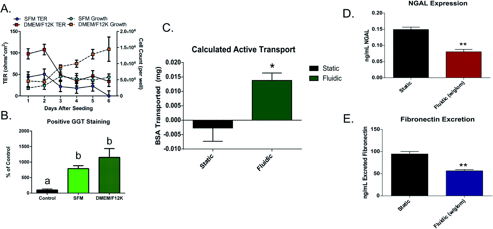 | ||
| Fig. 2 (A) Growth curves (solid lines) (n = 3 for SFM, n = 4 for DMEM/F12) and measurement of TER (dashed lines) in DMEM/F12 or SFM over a 6 day growth period (n = 5) (B) results of GGT staining in cells grown in either SFM or DMEM/F12 for 48 hours (n = 3). Results that do not share letters are significantly different determined by ANOVA post hoc testing at p < 0.05. (C) Results of BSA active transport in fluidic vs. static conditions (n = 3). (D) Quantitative results of NGAL and (E) fibronectin release in static and fluidic culturing conditions. A student's un-paired t-test was performed (**p < 0.01, n = 3). | ||
Immunohistochemistry (IHC) was performed to determine presence of caveolin-1, a marker for transcytotic vesicles22 as well as tight junction proteins occludin23 and ZO-1.24 The presence of these proteins shown qualitatively in Fig. 3A suggested that cells were forming junctions, and transporting macromolecules via transcytosis. Transport studies with fluorescently tagged occludin and BSA also supported this data as cells showed resistance to the diffusion of these 2–5 nm globular proteins through monolayers (BSA: 6.82-fold decrease; occludin: 4.88-fold decrease between controls and cell seeded membranes, figure not shown). BSA and ovalbumin showed evidence of possible active transport indicated by differences between protein transport at 4 °C (passive transport) and 37 °C (active transport), though not significant in static cultures (ESI Fig. 2†). Finally, to confirm the presence of the two main active transporters, caveolae25,26 and clathrin pits,27 immunofluorescent staining was performed in both control conditions and in the presence of inhibitors (nystatin and EIPA). Results indicated that both caveolae and clathrin was present in large quantities in this cell line (Fig. 3A and B), and inhibitors reduced clathrin expression by 1.7-fold (33.38 ± 3.51% and 19.75 ± 0.92% positive staining per field).
 | ||
| Fig. 3 (A) Results of protein staining for DNA, clathrin and caveolin-1 in control cell cultures and (B) cultures with EIPA and nystatin transport inhibitors. Magnification 80×, scale bar = 27.2 μm. Staining for F-actin after a 48 hour growth period under (C) static or (D) fluidic conditions (0.4 dyne cm−2). Arrow indicates direction of fluid movement. Cytoskeletal reorganization under shear stress can be qualitatively observed. (Magnification 40×) (E and F) qualitative and (G and H) quantitative results of clathrin and β-catenin expression in fluidic (0.8 dyne cm−2) conditions over various exposure periods compared against static cultures. No significant difference was observed in β-catenin staining, however significant differences in clathrin expression were observed in all durations of fluid shear stress tested compared to static cultures. An ANOVA with post hoc testing was performed to determine significance between treatments (n = 9, *p < 0.05, **p < 0.01). | ||
2. Device fabrication and characterization
In order to determine the effects of shear stress on HK-2 cells, single and multi-channel devices were fabricated as a bioreactor for these cells. An 8 nm-pore filter was added within the flow circuit to serve as the glomerulus, passively blocking large molecular weight compounds from entering the proximal tubule region of the bioreactor (Fig. 1).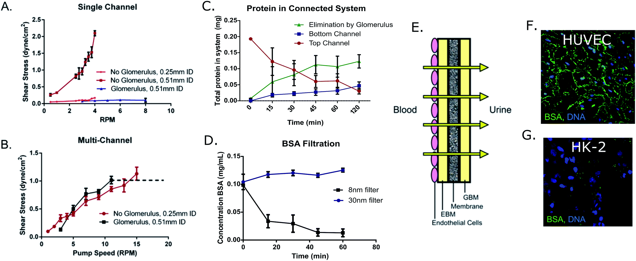 | ||
| Fig. 4 (A) Results from pump calibration with and without the 8 nm pore glomerulus attachment in the single channel device and the (B) 30 nm attachment in the multi-channel device, using either 0.51 mm or 0.25 mm inner diameter tubing. Overlap was observed between glomerulus and non-glomerulus devices around a 3.25 rpm pump rate (0.1 dyne cm−2) in the case of the 8 nm glomerulus. The glomerulus attachment began leaking at pump rates higher than 12 rpm (dashed line) using the 30 nm filter (n ≥ 4). (C) Tracking of protein in multi-channel device with glomerular attachment. Protein in the proximal tubule channel is decreasing as protein is being blocked by the glomerular filter, or transported back into the “bloodstream” channel in the bottom of the device. (D) Concentration of BSA in media filtrate solution after glomerular filtration (8 nm and 30 nm pore filter) over time (n = 3). (E) Layering of GBM (collagen type 1, heparin sulfate, collagen type 1), EBM, and endothelial cells on the glomerulus membrane to act as a barrier between bloodstream and urine ultrafiltrate. (F) Localization of fluorescently tagged BSA in HUVECs and (G) HK-2 cells. The localization of serum protein indicates passive transport in endothelial cells and active transport in the HK-2 epithelial cells. | ||
3. Cell characterization within microfluidic devices
3b.i. Clathrin and β-cantenin expression. Cells were seeded on fibronectin-treated membranes for a period of 24 hours (confluence was confirmed through live staining with calcein AM shown in Fig. 1D), then either left under static conditions in a 6-well plate, or placed within the multi-channel microfluidic device. Cells were exposed to either static conditions or a shear stress of 0.8 dyne cm−2 for 48 hours, and then stained for clathrin (major active transporter), and β-catenin (junctional protein) using ICC. A large up-regulation of clathrin was observed in fluidic cultures compared to static results as is shown qualitatively in Fig. 3E and F.
To determine the exposure time of shear stress required for this increased protein expression, the same experiment was repeated where cells were fixed after 0, 1, 5, 24, and 48 hours of exposure to 0.8 dyne cm−2 shear stress and stained for clathrin and β-catenin (Fig. 3G and H). There were no significant changes in β-catenin expression between static and any duration of fluidic exposure that was observed. However, a significant up-regulation in the active transporter protein, clathrin, was observed after just 1 hour of exposure to shear stress compared to static cultures. This significant up-regulation was maintained throughout the 48 hour testing period and is shown as % positive staining per field (static 3.16 ± 0.69%; 1 h 40.69 ± 8.38%; 5 h 50.89 ± 9.88%; 24 h 42.89 ± 11.39%; 48 h 51.17 ± 3.75%).
3b.ii. Protein transport. To study transport, a fluorescently tagged BSA solution (0.4 mg mL−1) was added to the top reservoir of either Transwells® (static) or multi-layered devices (0.8 dyne cm−2) for 2 hours at either 37 °C (active transport) or 4 °C (passive transport) against blank controls that were treated with fibronectin, but not seeded with cells. The results of these tests indicated that a significant increase in active protein transport occurred under fluidic conditions (0.014 ± 0.005 mg) compared to static culturing (−0.003 ± 0.008 mg) (Fig. 2C). Additionally, the fate of the tagged BSA protein was monitored through sampling of the top and bottom reservoirs of devices with glomerulus attachments. As shown in Fig. 4C, the concentration of serum protein decreases over time in the proximal tubule chamber (top channel) as protein is being actively transported to the bottom “bloodstream” channel or otherwise “eliminated” by the glomerular filter. Localization of this FITC-BSA protein was determined through confocal imaging of the HUVECs and HK-2 cells. In the HUVECs, BSA was localized in the junctions of these cell monolayers (Fig. 4F). By contrast, in the case of HK-2 cells which active transport proteins, BSA was localized in vesicles, rather than between cells (Fig. 4G) indicating passive and active transport for the endothelial and epithelial cells, respectively.
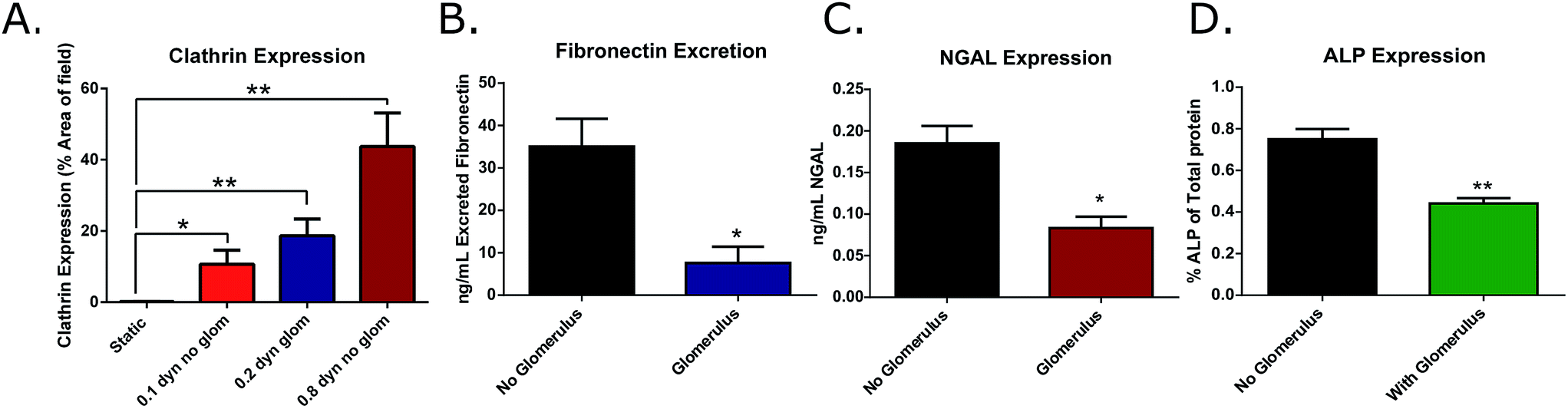
3b.iii. Expression of cell distress markers. To determine the effects of the addition of shear stress, and the filtration of the glomerulus device on cell distress biomarkers, the concentration of fibronectin and NGAL in cell culture supernatant was quantified in either static or fluidic (0.8 dyne cm−2) cultures (without a glomerulus attachment), and in cultures that were grown at 0.4 dyne cm−2 with and without a glomerulus attachment after 24 hours. Culture media was collected from the apical chambers of these devices and expression of these markers was quantified through the use of commercial ELISA kits. It was found that in the case of both NGAL and fibronectin, the concentration of these compounds was significantly lower in fluidic cultures (Fig. 2D and E), indicating a protective effect with the addition of shear stress (NGAL: static = 0.15 ± 0.01, fluidic = 0.08 ± 0.01 ng mL−1; fibronectin: static = 94.61 ± 5.52, fluidic = 56.39 ± 2.92 ng mL−1).
Filtration of media by the glomerular attachment also led to a significant decrease in the release of these distress markers in the proximal tubule chamber (NGAL: no glomerulus = 0.19 ± 0.02, glomerulus = 0.09 ± 0.01 ng mL−1; fibronectin: no glomerulus = 35.02 ± 6.59, glomerulus = 7.60 ± 3.86 ng mL−1; ALP: no glomerulus = 0.75 ± 0.05, glomerulus = 0.44 ± 0.03% ALP of total protein) (Fig. 5B–D). These results indicate the necessity of both fluidic shear stress, as well as serum filtration prior to exposing tubular cells to culture media to ensure healthy cell function.
 | ||
| Fig. 5 (A) Quantitative expression of clathrin under low shear stress conditions induced by the use of the smaller, more restrictive glomerulus pore size (8 nm) compared against physiological shear stress (n = 9). (B) Expression of fibronectin, (C) NGAL, and (D) ALP in microfluidic devices with and without the glomerulus filtration attachment in the top, proximal tubule channel. | ||
3b.iv. Effects of glomerulus-induced low shear stress on clathrin expression. Clathrin expression was monitored in cultures grown in either low shear stress (0.1 or 0.2 dyne cm−2), or intermediate shear stress (0.8 dyne cm−2) and with or without the glomerulus attachment. It was determined that there was a non-significant decrease in clathrin expression when shear stress was decreased due to restriction by the 8 nm filter (0.2 dyne cm−2), and this trend continued in the lower shear cultures lacking the filter (0.1 dyne cm−2). These results indicate that this clathrin activation pathway is not an on/off binary response, meaning that there can be varying degrees of protein expression depending on the level of shear stress to which the cells are being exposed. Although there was a slight decrease in overall expression of clathrin in these low-shear cultures, the expression remained significantly higher than the results obtained from static experiments (static = 0.18 ± 0.06%; 0.1 dyne cm−2 = 10.66 ± 3.96%; 0.2 dyne cm−2 = 18.68 ± 4.68%; and 0.8 dyne cm−2 = 43.74 ± 9.41% positive staining per field) (Fig. 5A). Therefore the use of the 8 nm filter allows for realistic protein filtration without significantly hindering the expression of active transport proteins, making it a viable addition to the microfluidic device.
Discussion
The results of these studies support the idea that this multi-layered microfluidic device platform could successfully be used in the culturing of human kidney cells. Studies by Jang et al.28 have shown that columnar height and polarization of proximal tubule cells increase when cells are grown on membrane supports compared to glass surfaces, and that shear stress further increases these factors through a synergistic effect. This allows for overall healthier cells that behave more realistically than in static cultures, or single channel devices. The addition of multiple fluidic layers also provides for the opportunity to study active and passive transport, the primary function of renal cells. The addition of a second fluidic layer was based off of a similar device design utilized in the works by Huh et al. for the modelling of air to liquid interfaces in the alveolar barrier of the lung tissue. Their models incorporated air flow in the top channel and “blood” flow in the bottom where cell culture medium was circulated through the system.29,30 We believe that circulating flow is not only necessary in the proximal tubule chamber of our device, but also in the bottom, “bloodstream” channel of our device to properly model the removal of compounds that have been reabsorbed by the renal tubule to prevent the effects of a concentration gradient that may occur in the case of a static well.In this study, clathrin expression was coupled with BSA protein transport, and it was found that active transport was amplified significantly after exposure to physiological shear stress. The results of this study may provide some insight as to why static cultures fail to predict toxicity of pharmaceutical compounds in pre-clinical trials, possibly due to an apparent lack of internalization. Additionally, it has been demonstrated by the work of Duan et al.31 that the introduction of fluid shear stress to renal tubular cells can cause cytoskeletal reorganization and junctional reformation. These results were also observed in our multi-layered devices through the elongation and alignment of cells along the direction of shear stress, leading to more physiologic cell morphology. Finally, culturing these cells under shear stress significantly reduced the release of cell distress markers fibronectin and NGAL compared to static controls. Based on the results of these studies, we believe that renal proximal tubule cells can successfully be growth within the proposed microfluidic device and elicit more physiological-like reactions to environmental or chemical stimulus than with traditional static culturing methods.
The model presented in this work has a few deviations from previous renal tubule microfluidic models. One deviation from many of the devices that are currently being created is the move to a more rigid, thermoplastic material, polycarbonate. PDMS and other elastomers have been shown to leach un-crosslinked oligomers into medium, absorb small molecules (affecting cell signaling and dosing concentrations for pharmaceuticals), and have a higher vapor permeability (which can have detrimental effects on micro- and nano-liter volumes).32,33 Additionally, polycarbonate is robust, meaning that these devices can be sterilized and re-used. In this study, tubing and polycarbonate sections of devices (non-cell contacting surfaces) were autoclaved and re-used to a maximum of 40 times before leaking occurred due to poor sealing (cell seeding membranes were not re-used). This may potentially save money and resources compared to single-use devices, as the modelling of barrier tissues not only applies to the kidney, but also to many other tissues which could easily be incorporated into this simple platform. However, the main novel addition to this device is the glomerular filtration chamber. Other microfluidic kidney models have not yet addressed this important barrier into the nephron. Cell culture media often contains proteins that may mimic the effects of proteinuria on renal proximal tubule cells. An over-reabsorption of proteins by proximal tubule cells has been shown to activate tubular-dependent pathways of interstitial inflammation, leading to a fibrotic cell phenotype.34 In this study, it was found that the addition of media filtration prior to flow into the tubule chambers led to an overall reduction in cell distress makers (ALP, NGAL, fibronectin excretion), allowing for much more physiological cell growth. A glomerulus-like filter could therefore be used to remove or prevent these proteins from being introduced to cell cultures, but still circulate to other co-cultured cells.
To expand upon the glomerular filter, we have seeded endothelial cells upon a membrane with realistic pore sizes that allow for physiological size-exclusive filtration. This glomerular membrane also contains a realistic epithelial basal membrane (EBM) and negatively charged glomerular basal membrane (GBM), allowing for potential charge-selective filtration. A healthy glomerular barrier consists of 3 distinct layers; the endothelial layer, the ECM, and the podocyte cell layer. Here, we have incorporated the endothelial layer, as well as the ECM (endothelial and glomerular basal membrane), recapitulating 2 of these physiological layers with the potential to add podocytes to the GBM in later works. Using this simplified device setup, we have demonstrated the ability to model the passive filtration barrier of the glomerulus as well as the active transport of compounds observed in the proximal tubule. BSA was observed to have gathered in the junctions of the epithelial cells (HUVECs) in the glomerulus device (paracellular transport), and within vesicles of the HK-2 cells, indicating transcellular transport pathways.
In addition to this realistic protein filtration and reuptake, here we have demonstrated that not only is shear stress necessary for healthy renal tubule cell behavior, but also the filtration of the primary urine in the glomerulus, as cultures that did not have this glomerular barrier indicated higher release of distress markers such as ALP, NGAL and fibronectin ECM deposition. By seeding cells upon this filtration barrier, it may be possible to model endotheliosis, or through the future addition of podocytes to this membrane, more complex glomerular diseases may be possible to monitor. The co-culture of proximal tubule cells with endothelial cells may also lead to increased tubule functionality and a “healthier” overall phenotype. Previous studies by Tasnim and Zink have demonstrated an increase in proliferation, tubule-specific gene expression, and enzyme activity in primary human proximal tubule cells (HPTC) when co-cultured with endothelial cells (HUVEC). Their results indicated increases in HUVEC hepatocyte growth factor (HGF), vascular endothelial growth factor (VEGF), TGF-β1, and α2-macroglobulin expression in the proximal tubule co-culture environment. It was believed that the tubule cells stimulated the production of these factors in the HUVECs, which then went on to increase tubular function, leading to increased cell counts, junction formation and cell maintenance.35 Endothelial nitric oxide synthase (eNOS) has also been implicated in the modulation of proximal tubule transport and acid base balance.36 It is possible that not only the filtration allowed by the glomerular attachment leads to increased functionality, but also that the crosstalk between co-cultured epithelial and endothelial cells has positive effects on cell growth and behavior. Finally, with recent advances in microfluidics, there is a push to add additional functionality to these fluidic organ-on-a-chip devices, moving toward a potential body-on-a-chip with multiple organs connected within a single device. This glomerular barrier would prevent unrealistic cell signaling between other organs and the kidney, while providing realistic separation between the bloodstream and proximal tubule. This passive filtration apparatus would help move toward the use of a universal blood substitute, where other organ chambers could receive necessary nutrients through serum proteins, but prevent proteinuria in the kidney growth chambers.
Conclusions
The multi-layered microfluidic device proposed in this work allows for a close approximation of the in vivo environment that proximal tubule cells flourish in. Through the introduction of a physiologically relevant shear stress of 0.8 dyne cm−2, a glomerulus-modelling filter attachment and 2 independent fluidic channels, we have been able to provide an improved growth environment over traditional culture methods. It has been observed that cells undergo increased junctional formation, polarization, cytoskeletal reorganization and a significant up-regulation in transport proteins within this device. This large increase in active transport proteins under flow may provide some insight into why traditional methods of drug screening (static culturing) fail to predict toxic effects that later emerge during human trials. To confirm these suspicions, further research will be performed on drug toxicity in static and fluidic conditions. Additionally, this device incorporates the first example of a glomerular filtration model, allowing for the creation of more realistic “primary urine” for the culture of proximal tubule cells downstream. Here, we have demonstrated both the passive filtration barrier function of the human glomerulus, as well as the subsequent reuptake of serum proteins in the proximal tubule.Acknowledgements
This work was supported by the Clifford D. Clark Graduate Fellowship (CMS), and by a grant to the State University of New York at Binghamton from the Howard Hughes Medical Institute through the Precollege and Undergraduate Science Education Program..References
- M. Leist, N. Hasiwa, C. Rovida, M. Daneshian, D. Basketter, I. Kimber, H. Clewell, T. Gocht, A. Goldberg, F. Busquet, A. M. Rossi, M. Schwarz, M. Stephens, R. Taalman, T. B. Knudsen, J. McKim, G. Harris, D. Pamies and T. Hartung, ALTEX, 2014, 31, 341–356 Search PubMed.
- M. Leist and T. Hartung, ALTEX, 2013, 30, 227–230 CrossRef PubMed.
- A. Harding, More compounds failing phase I, The Scientist, 2004 Sept 13 Search PubMed.
- M. H. Wu, S. B. Huang and G. B. Lee, Lab Chip, 2010, 10, 939–956 RSC.
- E. I. Christensen, H. Birn, T. Storm, K. Weyer and R. Nielsen, Physiology, 2012, 27, 223–236 CrossRef CAS PubMed.
- H. Y. Tiong, P. Huang, S. Xiong, Y. Li, A. Vathsala and D. Zink, Mol. Pharmaceutics, 2014, 11, 1933–1948 CrossRef CAS PubMed.
- Y. Li, Z. Y. Oo, S. Y. Chang, P. Huang, K. G. Eng, J. L. Zeng, A. J. Kaestli, B. Gopalan, K. Kandasamy, F. Tasnim and D. Zink, Toxicol. Res., 2013, 2, 352–365 RSC.
- K. J. Jang and K. Y. Suh, Lab Chip, 2010, 10, 36–42 RSC.
- K. J. Jang, H. S. Cho, H. Kang do, W. G. Bae, T. H. Kwon and K. Y. Suh, Integr. Biol., 2011, 3, 134–141 RSC.
- V. Raghavan, Y. Rbaibi, N. M. Pastor-Soler, M. D. Carattino and O. A. Weisz, Proc. Natl. Acad. Sci. U. S. A., 2014, 111, 8506–8511 CrossRef CAS PubMed.
- A. G. Sciancalepore, F. Sallustio, S. Girardo, L. Gioia Passione, A. Camposeo, E. Mele, M. Di Lorenzo, V. Costantino, F. P. Schena and D. Pisignano, PLoS One, 2014, 9, e87496 Search PubMed.
- E. M. Frohlich, J. L. Alonso, J. T. Borenstein, X. Zhang, M. A. Arnaout and J. L. Charest, Lab Chip, 2013, 13, 2311–2319 RSC.
- M. J. Ryan, G. Johnson, J. Kirk, S. M. Fuerstenberg, R. A. Zager and B. Torok-Storb, Kidney Int., 1994, 45, 48–57 CrossRef CAS PubMed.
- R. B. Klassen, K. Crenshaw, R. Kozyraki, P. J. Verroust, L. Tio, S. Atrian, P. L. Allen and T. G. Hammond, Am. J. Physiol., 2004, 287, F393–F403 CrossRef CAS PubMed.
- D. Sahali, N. Mulliez, F. Chatelet, R. Dupuis, P. Ronco and P. Verroust, J. Exp. Med., 1988, 167, 213–218 CrossRef CAS PubMed.
- J. V. Bonventre, V. S. Vaidya, R. Schmouder, P. Feig and F. Dieterle, Nat. Biotechnol., 2010, 28, 436–440 CrossRef CAS PubMed.
- R. A. Rhoades and D. R. Bell, Medical Physiology: Principals for Clinical Medicine, Lippincott Williams & Wilkins, Baltimore, MD, 4th edn, 2013 Search PubMed.
- A. M. Rutenburg, H. Kim, J. W. Fischbein, J. S. Hanker, H. L. Wasserkrug and A. M. Seligman, J. Histochem. Cytochem., 1969, 17, 517–526 CrossRef CAS PubMed.
- J. E. Sidaway, R. G. Davidson, F. McTaggart, T. C. Orton, R. C. Scott, G. J. Smith and N. J. Brunskill, J. Am. Soc. Nephrol., 2004, 15, 2258–2265 CrossRef CAS PubMed.
- R. Agarwal, Mayo Clin. Proc., 2007, 82, 1381–1390 CrossRef CAS PubMed.
- H. A. Praetorius and K. R. Spring, J. Membr. Biol., 2001, 184, 71–79 CrossRef CAS PubMed.
- M. Drab, P. Verkade, M. Elger, M. Kasper, M. Lohn, B. Lauterbach, J. Menne, C. Lindschau, F. Mende, F. C. Luft, A. Schedl, H. Haller and T. V. Kurzchalia, Science, 2001, 293, 2449–2452 CrossRef CAS PubMed.
- M. Furuse, T. Hirase, M. Itoh, A. Nagafuchi, S. Yonemura, S. Tsukita and S. Tsukita, J. Cell Biol., 1993, 123, 1777–1788 CrossRef CAS PubMed.
- J. M. Anderson, B. R. Stevenson, L. A. Jesaitis, D. A. Goodenough and M. S. Mooseker, J. Cell Biol., 1988, 106, 1141–1149 CrossRef CAS PubMed.
- M. P. Lisanti, P. E. Scherer, J. Vidugiriene, Z. Tang, A. Hermanowski-Vosatka, Y. H. Tu, R. F. Cook and M. Sargiacomo, J. Cell Biol., 1994, 126, 111–126 CrossRef CAS PubMed.
- M. P. Lisanti, Z. Tang, P. E. Scherer, E. Kubler, A. J. Koleske and M. Sargiacomo, Mol. Membr. Biol., 1995, 12, 121–124 CrossRef CAS PubMed.
- J. S. Rodman, D. Kerjaschki, E. Merisko and M. G. Farquhar, J. Cell Biol., 1984, 98, 1630–1636 CrossRef CAS PubMed.
- K. J. Jang, A. P. Mehr, G. A. Hamilton, L. A. McPartlin, S. Chung, K. Y. Suh and D. E. Ingber, Integr. Biol., 2013, 5, 1119–1129 RSC.
- D. Huh, H. Fujioka, Y. C. Tung, N. Futai, R. Paine, 3rd, J. B. Grotberg and S. Takayama, Proc. Natl. Acad. Sci. U. S. A., 2007, 104, 18886–18891 CrossRef CAS PubMed.
- D. Huh, B. D. Matthews, A. Mammoto, M. Montoya-Zavala, H. Y. Hsin and D. E. Ingber, Science, 2010, 328, 1662–1668 CrossRef CAS PubMed.
- Y. Duan, N. Gotoh, Q. Yan, Z. Du, A. M. Weinstein, T. Wang and S. Weinbaum, Proc. Natl. Acad. Sci. U. S. A., 2008, 105, 11418–11423 CrossRef CAS PubMed.
- M. W. Toepke and D. J. Beebe, Lab Chip, 2006, 6, 1484–1486 RSC.
- K. J. Regehr, M. Domenech, J. T. Koepsel, K. C. Carver, S. J. Ellison-Zelski, W. L. Murphy, L. A. Schuler, E. T. Alarid and D. J. Beebe, Lab Chip, 2009, 9, 2132–2139 RSC.
- G. Remuzzi, Curr. Opin. Nephrol. Hypertens., 1999, 8, 655–663 CrossRef CAS PubMed.
- F. Tasnim and D. Zink, American Journal of Physiology – Renal Physiology, 2012, 302, F1055–F1062 CrossRef CAS PubMed.
- T. Wang, American Journal of Physiology – Renal Physiology, 2002, 283, F658–F662 CrossRef PubMed.
Footnote |
| † Electronic supplementary information (ESI) available. See DOI: 10.1039/c6ra25641d |
| This journal is © The Royal Society of Chemistry 2017 |