
 Open Access Article
 This Open Access Article is licensed under a
 Creative Commons Attribution 3.0 Unported Licence
Novel π-conjugated iron oxide/reduced graphene oxide nanocomposites for high performance electrochemical supercapacitors†
Gourav Bhattacharyaa,
Ganeshlenin Kandasamy b,
Navneet Soinc,
Ravi Kant Upadhyaya,
Sujit Deshmukha,
Dipak Maityb,
James McLaughlind and
Susanta Sinha Roy*a
b,
Navneet Soinc,
Ravi Kant Upadhyaya,
Sujit Deshmukha,
Dipak Maityb,
James McLaughlind and
Susanta Sinha Roy*a
aDepartment of Physics, School of Natural Sciences, Shiv Nadar University, Gautam Buddha Nagar 201314, Uttar Pradesh, India. E-mail: susanta.roy@snu.edu.in
bNanomaterials Lab, Department of Mechanical Engineering, School of Engineering, Shiv Nadar University, Gautam Buddha Nagar 201314, Uttar Pradesh, India
cInstitute for Materials Research and Innovation (IMRI), University of Bolton, Deane Road, Bolton, BL3 5AB, UK
dNanotechnology and Integrated Bioengineering Centre, University of Ulster, Jordanstown Campus, Newtownabbey, BT37 OQB, Northern Ireland, UK
First published on 23rd December 2016
Abstract
A novel nanocomposite consisting of π-conjugated 2-aminoterephthalic acid (ATA) coated iron oxide (Fe3O4) nanoparticles and reduced graphene oxide (RGO) has been synthesized using a facile combination of wet-chemistry and low-power sonication. The ATA–Fe3O4/RGO nanocomposites exhibited a high specific capacitance of the order of 576 F g−1; significantly higher than that of pristine Fe3O4 (132 F g−1) and RGO (60 F g−1) counterparts, indicative of a synergistic effect between the ATA–Fe3O4 and RGO components. Furthermore, the maximum energy storage density was calculated to be 75 W h kg−1 (at a current density of 6 A g−1). The charging–discharging analysis showed promising long-term stability with nearly 86% retention of the capacitance after 5000 cycles. The superior capacitive behaviour of these ATA–Fe3O4/RGO nanocomposites is attributed to the synergistic effect of the π-conjugated ATA coating on Fe3O4 which enhances the pseudo-capacitive charge transfer process of Fe3O4 and works in conjunction with the surface functional groups (such as carboxylic, amino and amide) present on the RGO surface, providing enhanced double layer capacitance. Thus, the current system exploits the advantages of both the double layer capacitors and pseudocapacitors in a hybrid structure.
1. Introduction
Recently, supercapacitors have garnered huge attention as portable power sources and power storage units. Furthermore, owing to their high energy density, long cycling life and capability to provide large power densities, they have been explored as starting power banks for renewable energy systems such as electrical vehicles and stationary fuel cells.1–6 The charge storage mechanism in supercapacitors mainly follows two routes: electrochemical double layer (EDLC) and pseudocapacitance.7,8 The EDLCs work on the principal of electrostatic charge storage using reversible adsorption of electrolyte ions onto electrochemically stable high surface area carbon materials, while on the other hand the pseudocapacitors rely on the use of conducting polymers9 and transition metal oxides10 to generate high capacitance via fast faradic reactions occurring at or near the solid electrode surface. In EDLCs, where the charge storage is non-faradic and electrostatic in nature, electrolyte ions are adsorbed onto the high surface area carbon-based materials such as carbon black, mesoporous carbon, carbon nanotubes (CNTs)11,12 and more recently graphene.13,14 Due to the charge separation at the electrode–electrolyte interface, the double layer capacitance is produced which is described by the classic Helmholtz capacitance leading to the formation of EDLC.15 In the case of EDLCs, high capacitance can be obtained by increasing the surface area and electrical conductivity of the material.5,16 The exotic properties of graphene such as extremely high surface area, chemical stability, high electrical conductivity and mechanical strength makes it a prospective and promising candidate for supercapacitor applications.17,18 Moreover, the use of graphene as electrode material eliminates the need for separate current collector and where a current collector is still used, it reduces the contact resistance between current collector and electrodes owing to an additional advantage of low charge transfer resistance, thereby providing an additional benefit.19,20 The interest in pseudocapacitors arises from the higher value of capacitance and energy density obtained as compared to the EDLCs.21,22 While pseudocapacitors provide very high capacitance and power densities, however, their relatively low electrical conductivity and poor stability limit their usage.23 In order to increase their conductivity, they are often blended with other conductive carbon materials such as carbon black, CNTs and more recently, graphene.24 Graphene based nanocomposites have been used extensively in various electrochemical applications.25 Among the various transition metal oxides such as ruthenium oxide (RuO2), manganese oxide (MnO2),26 nickel oxide (NiO), copper oxide (CuO)27 etc., iron oxide (Fe3O4) is one of the most suitable and promising materials owing to its cost effectiveness and environmentally benign nature.28 In spite of its high pseudo-charge, the overall capacitance value is low because of its poor electrical conductivity thereby limiting the ion diffusion.29 It has been reported earlier that the mixing of conductive materials such as carbon nanotubes (CNT) and activated carbon etc. with Fe3O4 improves the overall capacitance of such systems significantly.30,31Hybrid supercapacitors, utilizing both the faradic and non-faradic charge storage, potentially offer a solution to obtain high energy and power densities at the same time. Recently, graphene–metal oxide nanocomposites have been studied extensively as electrode materials,32,33 where the fast faradic reactions occurring on the metal oxide surface in conjunction with high conductivity of graphene tremendously improved the overall electrochemical performance of these nanocomposites.34,35 Chemically functionalized graphene increases its effective electrochemical surface area by enhancing the number of sites where the electrolyte adsorption can take place.13,36 Considering the above advantages, it is highly important to explore various graphene–metal oxide based advanced nanocomposites with enhanced electrochemical properties.
In this work, we have implemented an advanced strategy to enhance the capacitive performance of ATA–Fe3O4/RGO nanocomposites by increasing the double layer as well as pseudocapacitive behaviour, simultaneously. The carboxylic (–COOH) and amino (–NH2) groups of 2-aminoterephthalic acid coated iron oxide nanoparticles interact synergistically with the residual functional groups on the partially reduced graphene oxide to exhibit supercapacitive behaviour as analysed by cyclic voltammetry, electrochemical impedance and galvanostatic charging–discharging measurements.
2. Materials and methods
2.1. Materials
Ferrous chloride [Fe(Cl)2·4H2O], ferric chloride [Fe(Cl)3·6H2O], 2-aminoterephthalic acid (ATA), ammonium hydroxide (NH4OH) and potassium hydroxide (KOH) were purchased from Fisher Scientific. Graphene oxide (GO) was purchased from Sigma Aldrich. All the aqueous solutions were prepared with ultrapure water (Millipore-Q systems: measured electrical resistivity ∼ 18 MΩ cm at room temperature (298 K)).2.2. Synthesis
![[thin space (1/6-em)]](https://www.rsc.org/images/entities/char_2009.gif) :Fe3O4 = 1:3, the complete procedure has been reported previously in the literature.37 In order to investigate the role of amount of ATA on the electrochemical performance, the molar ratio was further varied to ATA:Fe3O4 = 2:3 and ATA:Fe3O4 = 1:6. The samples were marked as ATA-1 M (1:3), ATA-2 M (2:3) and ATA-0.5 M (1:6). The ATA coated iron oxide nanoparticles were then used for the preparation of nanocomposites with reduced graphene oxide. Uniform aqueous dispersions of partially reduced graphene oxide and ATA–Fe3O4 at various concentrations were prepared. Four weight ratios of iron oxide/RGO (ATA–Fe3O4:RGO = 1:2, 1:1, 2.5:1, 5:1) nanocomposites, having different concentrations in aqueous solutions (0.1 mg ml−1, 0.5 mg ml−1, 1 mg ml−1, 2 mg ml−1) were then added and ultrasonicated in a low power (50 W) bath sonicator at room temperature for 30 minutes to obtain nanocomposites. Low power sonication method has been reported earlier in the literature38 to produce RGO based nanocomposites.
:Fe3O4 = 1:3, the complete procedure has been reported previously in the literature.37 In order to investigate the role of amount of ATA on the electrochemical performance, the molar ratio was further varied to ATA:Fe3O4 = 2:3 and ATA:Fe3O4 = 1:6. The samples were marked as ATA-1 M (1:3), ATA-2 M (2:3) and ATA-0.5 M (1:6). The ATA coated iron oxide nanoparticles were then used for the preparation of nanocomposites with reduced graphene oxide. Uniform aqueous dispersions of partially reduced graphene oxide and ATA–Fe3O4 at various concentrations were prepared. Four weight ratios of iron oxide/RGO (ATA–Fe3O4:RGO = 1:2, 1:1, 2.5:1, 5:1) nanocomposites, having different concentrations in aqueous solutions (0.1 mg ml−1, 0.5 mg ml−1, 1 mg ml−1, 2 mg ml−1) were then added and ultrasonicated in a low power (50 W) bath sonicator at room temperature for 30 minutes to obtain nanocomposites. Low power sonication method has been reported earlier in the literature38 to produce RGO based nanocomposites.2.3. Experimental
3. Results and discussions
3.1. Morphology analysis
For direct morphological visualization, SEM images were taken for ATA–Fe3O4/RGO nanocomposites and is represented in the Fig. S1 (ESI†), wherein the figures show the decoration of iron oxide nanoparticles on RGO flakes. TEM analysis was carried out to analyse the morphology and microstructural properties of the pristine components and the ATA–Fe3O4/RGO nanocomposites. The TEM images of nanocomposite samples are shown in Fig. 1. It can be clearly seen from the image (Fig. 1a) that the sample consists of spherical ATA–Fe3O4 nanoparticles, with a size range of 4–10 nm. The selected area electron diffraction (SAED) pattern further confirms high crystallinity of the sample (Fig. 1b). The TEM image (Fig. 1d and e) of the ATA–Fe3O4/RGO nanocomposites at a weight ratio of 1:1 clearly shows the attachment of ATA–Fe3O4 onto the RGO sheet surface.
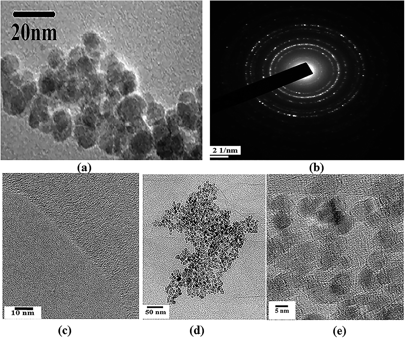 | ||
| Fig. 1 (a and c) correspond to TEM images of ATA coated iron oxide and RGO ((b) represents the SAED pattern of Fe3O4). (d and e) correspond to TEM images of ATA–Fe3O4/RGO nanocomposite of weight ratio ATA–Fe3O4:RGO = 1:1 at different resolutions. | ||
To further investigate the crystal structure of the nanocomposites, XRD analysis was performed (Fig. S2, ESI†). XRD peaks were found to be in close proximity with the standard peaks for inverse spinel phase of Fe3O4 (JCPDS card no. 19-0629). The broad hump between the 2θ values of 20–30° correspond to the relatively short range ordering of RGO (inset of Fig. S2†). This hump is also present in the XRD pattern of the ATA–Fe3O4–RGO nanocomposites. For GO, the diffraction peak appearing around 10.7° (inset Fig. S2†) became broader and less prominent for the case of RGO. From XRD spectra, the d spacing of GO was found to be 0.825 nm. This high d-spacing indicates the intercalation of water molecules as well as the formation of oxygen containing functional groups in between graphitic layers. For RGO samples, the low angle broad peak indicates the residual oxygen containing functional groups still present in RGO. The inter-planer spacing of RGO was also evaluated to be 0.378 nm (from the higher angle peak of RGO), thereby confirming the reduction of GO to RGO.
Reduction of GO to RGO was also monitored and confirmed using Raman spectroscopy (Fig. S3, ESI†). The intensity ratio of the D to the G band (ID/IG) for GO was found to be 0.911, which increased to 1.04 in the case of RGO. This increase in the ID/IG ratio for RGO suggests that the reduction process has altered the structure of GO with more structural defects.40,41 This was accompanied by the movement of the G band to lower peak position (1588 cm−1 for RGO) as compared to GO (1592 cm−1) with a reduction in the FWHM as well (from 62 cm−1 to 54 cm−1), further confirming the reduction of GO. This change in the peak position, suggests a decrease in the average size of the sp2 domains upon reduction of the GO,42 whereas the decrease in the FWHM indicates enhanced sp2 carbon atoms.43 Apart from the increase in the ID/IG ratio, a comparatively more prominent 2D peak in the Raman spectrum of RGO was also observed.
The possible mode of attachment of the ATA–Fe3O4 on the RGO sheet is described by the schematic shown in Fig. 2. There are mainly three possible ways of attachments: (i) attachment of –NH2 (amino) group of ATA with –COOH (carboxylic) group of RGO to form –CONH (amide) linkage; (ii) physical adsorption of nanoparticles over RGO and (iii) attachment of nanoparticles at the defect sites of the RGO. The presence of amino and carboxylic groups on the surface of nanocomposites is confirmed by FTIR analysis (1470 cm−1 (–NH bending), 1725 cm−1 (C![[double bond, length as m-dash]](https://www.rsc.org/images/entities/char_e001.gif) O stretching) and 3210 cm−1 (O–H stretching)) (Fig. S4, ESI†). The study also reveals the –CONH linkage between the particles (1570 cm−1) which is in accordance to our proposed interaction scheme (marked 1 in Fig. 2). From the inset of Fig. S4 (ESI†), it is quite evident that the peak corresponds to hydroxyl group for RGO decreases significantly than that of GO (3210 cm−1). Also, previously proposed mechanism for the reduction of GO to RGO suggested that the hydride transfer to epoxide is one of the key step in the reduction process. From the figure, it is also evident that the area under the curve for the epoxide region 870–1170 cm−1 decreased significantly in case of RGO implying the reduction of GO.
O stretching) and 3210 cm−1 (O–H stretching)) (Fig. S4, ESI†). The study also reveals the –CONH linkage between the particles (1570 cm−1) which is in accordance to our proposed interaction scheme (marked 1 in Fig. 2). From the inset of Fig. S4 (ESI†), it is quite evident that the peak corresponds to hydroxyl group for RGO decreases significantly than that of GO (3210 cm−1). Also, previously proposed mechanism for the reduction of GO to RGO suggested that the hydride transfer to epoxide is one of the key step in the reduction process. From the figure, it is also evident that the area under the curve for the epoxide region 870–1170 cm−1 decreased significantly in case of RGO implying the reduction of GO.
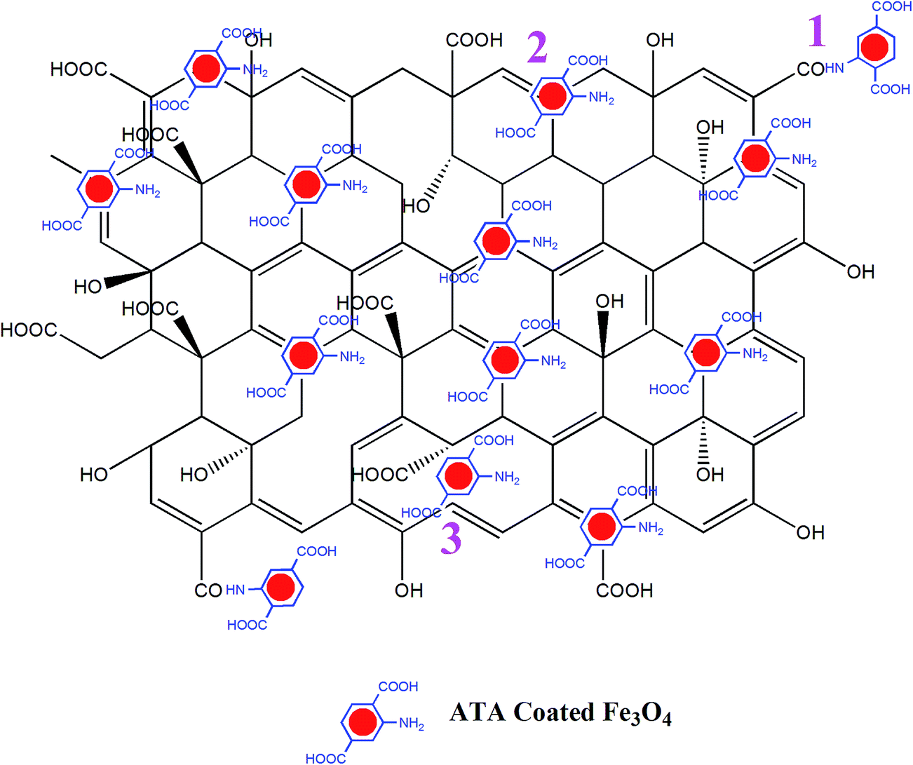 | ||
| Fig. 2 Three distinct possibilities of attachment of ATA coated iron oxide nanoparticles over RGO are shown in the schematic. | ||
To further investigate the attachment of ATA on Fe3O4 and the interaction between ATA–Fe3O4 and RGO, UV-Visible spectra was recorded in absorbance mode in the wavelength range of 200–900 nm (Fig. S5, ESI†). The uncoated Fe3O4 does not exhibit any considerable strong absorption peaks and matches with the literature. ATA samples show two characteristic peaks around ∼355 nm and ∼245 nm. The strong absorption around ∼355 nm is attributed to the π–π* transition of lone pair of amino group.44 Whereas the ATA coated sample clearly displays two sharp peaks at 330 nm and 220 nm which are in agreement with the reported values.45 The blue shift in case of the coated sample could be ascribed as the perturbation by the metallic centre46,47 of Fe3O4. In case of ATA–Fe3O4:RGO nanocomposite sample, the peaks become sharper indicating a strong attachment.
3.2. Electrochemical analysis
:1 loading at a concentration of 1 mg ml−1 of ATA–Fe3O4 and RGO shows the highest specific capacitance value at a scan rate 50 mV s−1 (Fig. S6 and Table S1, ESI†). It has previously been reported that at higher loadings, the agglomeration and formation of clusters of Fe3O4 nanoparticles leads to a lower electrochemical surface area thereby leading to a reduction in the specific capacitance of the samples.48 The CV scans (Fig. 3a) carried out for incremental scan rates of 10–100 mV s−1 for the 1:1 ratio of ATA–Fe3O4:RGO nanocomposite between −0.4 to 0.8 V look relatively featureless and exhibit a nearly rectangular shape, representative of the supercapacitor behaviour.49 A small peak corresponding to the Fe(III)–Fe(II) transition is observed at around −0.1 V (Fig. S7, ESI†). It is to be mentioned that for uncoated iron oxide the corresponding peak lies in more negative voltage (≤−0.25 V) and is reported in literature.33 In the present study, the CV of uncoated and ATA coated iron oxide is plotted in Fig. S8 (ESI†) wherein the shift in the reduction peak can be attributed to the ATA attachment. This quasi-rectangular shape of the CV curve is suggestive of the ideal double layer capacitance with fast charge transport.50 In fact, the currents obtained for the ATA–Fe3O4/RGO composites are significantly higher than that of pristine ATA–Fe3O4 and pristine RGO samples, indicating enhanced electrochemical charge storage capabilities of the nanocomposites. The specific-capacitance is calculated from the cyclic voltammetry curve using the following equation:where Cs is the specific capacitance, dV/dt represents the scan rate and m is the active mass of the material on the GCE. The factor 0.5 is multiplied to get either cathodic or anodic current.
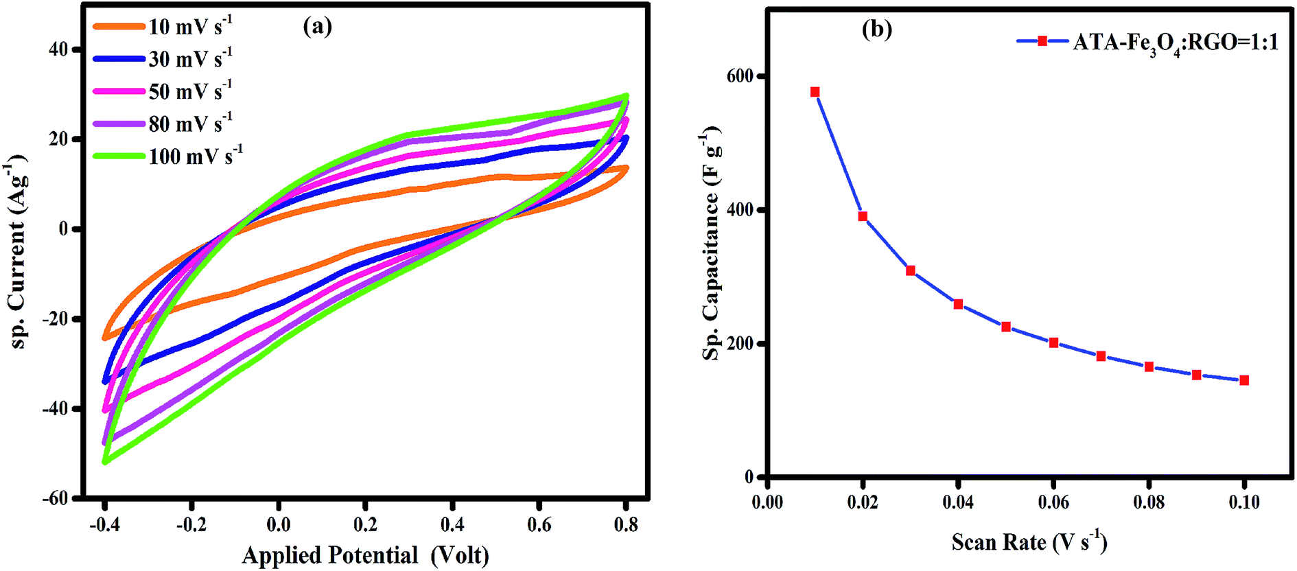 | ||
| Fig. 3 (a) Cyclic voltammogram of ATA–Fe3O4/RGO nanocomposite (ATA–Fe3O4:RGO = 1:1) in 1 M aqueous KOH solution. (b) is the variation of specific capacitance with scan rate for ATA–Fe3O4/RGO nanocomposite (ATA–Fe3O4:RGO = 1:1) in 1 M aqueous KOH solution. | ||
Once it had been established that the 1:1 loading of ATA–Fe3O4 and RGO shows the highest specific capacitance, the concentration of the nanocomposites (ATA–Fe3O4:RGO = 1:1) in aqueous solution was varied, wherein the maximum capacitance is observed at a concentration of 1 mg ml−1 (Fig. S7, ESI†). The specific capacitance of the nanocomposites as a function of scan rate is plotted in Fig. 3b, wherein at the lowest scan rate of 10 mV s−1 the capacitance of ATA–Fe3O4/RGO nanocomposites is found to be 576 F g−1 (132 F g−1 and 60 F g−1 for pristine ATA coated Fe3O4 and partially reduced graphene oxide, respectively at the same scan rates). It is important to mention that at the scan rate of 50 mV s−1, the capacitance for pristine ATA coated Fe3O4 and partially reduced graphene oxide is found to be 30 F g−1 and 17 F g−1, respectively. Thus, the significant increase in capacitance value of the composites (245 F g−1 at scan rate 50 mV s−1) can be credited to the synergistic effect of both the materials.51 The π-conjugation path favours the effectual spin-transfer from the metallic core of iron oxides to the external surfaces that are in contact with the bulk, for instance, the surrounding electrolyte environment. Thus, the π-conjugation of ATA coating with Fe3O4 nanoparticles enhances the fast charge transfer kinetics and consequently the faradic capacitance52 of the nanocomposite system. The specific amount of ATA would provide the uniform coating of Fe3O4. The amount of ATA is important to form an optimal colloidal suspension which would lead to minimal agglomeration of Fe3O4 nanoparticles. To study the effect of mass of ATA on capacitance performance cyclic voltammetry analysis was carried by varying the molar ratio between ATA and Fe3O4 (Fig. S9, ESI†). From the figure, it is clear that the ATA-1 M sample exhibit the highest specific capacitance amongst all the samples as at this molar ratio, the Fe3O4 nanoparticles are uniformly coated with least agglomeration. Due to the optimal coating, the ATA–Fe3O4 samples present the highest surface area and enhanced wettability leading to enhanced electrochemical performance.
| Cs = −[i/{(dV/dt) × m}] |
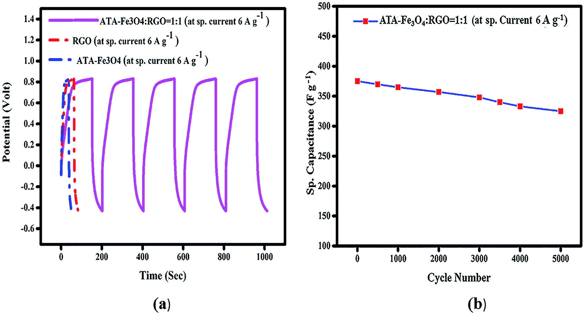 | ||
| Fig. 4 (a) Galvanostatic charge/discharge curve of ATA coated Fe3O4, RGO and ATA–Fe3O4/RGO nanocomposite (ATA–Fe3O4:RGO = 1:1) in 1 M KOH solution at sp. current 6 A g−1. (b) The cycling performance of ATA–Fe3O4/RGO nanocomposite (ATA–Fe3O4:RGO = 1:1) in 1 M KOH solution at sp. current 6 A g−1 (up to 5000 cycle). The cycling performance of ATA–Fe3O4/RGO nanocomposite (ATA–Fe3O4:RGO = 1:1) in 1 M KOH solution at sp. current 6 A g−1 (up to 5000 cycle). | ||
To probe the long-term stability and durability, we performed charging discharging analysis for an extensive number of cycles and the variation of specific capacitance with each cycle is plotted in Fig. 4b. The result shows that nearly 86% of the starting capacitance values are retained even after 5000 cycles. It has been reported earlier that the agglomeration of the metal oxide nanoparticles during the electrochemical charging is the root cause of the decline in cyclic performance.48 In the literature, it has been reported that the presence of graphene provides a favourable surface for the adsorption of nanoparticles which avoids their agglomeration.61 However, in our study it is revealed that in spite of presence of RGO, the uncoated Fe3O4 nanocomposite shows relatively low capacitance value, thus indicating that the surface functional groups and coating on the Fe3O4 nanoparticles play a key role in prevention of agglomeration.
The energy density of the nanocomposite is further calculated by employing the formula:
| E = 0.5CsV2 |
:1) composite (at 1 mg ml−1) is found to be 75 W h kg−1 for 6 A g−1 current, which is significantly higher than previously reported values 67 W h kg−1 for 5 A g−1.33 The power density of the same sample is also calculated and is found to be 3500 W kg−1. These enhanced values are observed on account of strong interactions between the ATA–Fe3O4 and RGO, wherein the surface coating and π-conjugation of ATA play an important part leading to an enhanced overall performance of the supercapacitor.
:1) nanocomposites. The diameter of the semicircle of the Nyquist plot provides the magnitude of the charge transfer resistance.68 The inset of Fig. 6 shows less circularity of impedance data corresponding to a smaller charge-transfer resistance, which is favourable for supercapacitor materials, thereby suggesting that the electrochemical performance is enhanced due to the synergistic effect between the ATA–Fe3O4 and RGO.69,70
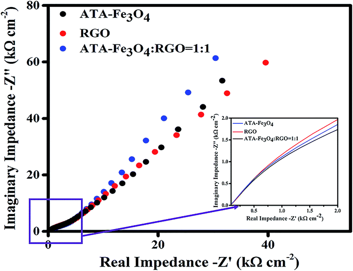 | ||
| Fig. 5 Nyquist plot of experimental impedance data for ATA–Fe3O4, RGO and ATA–Fe3O4/RGO nanocomposite (ATA–Fe3O4:RGO = 1:1) in the frequency range of 100 kHz to 100 Hz. Inset shows the zoomed view at high frequencies (>5 kHz). | ||
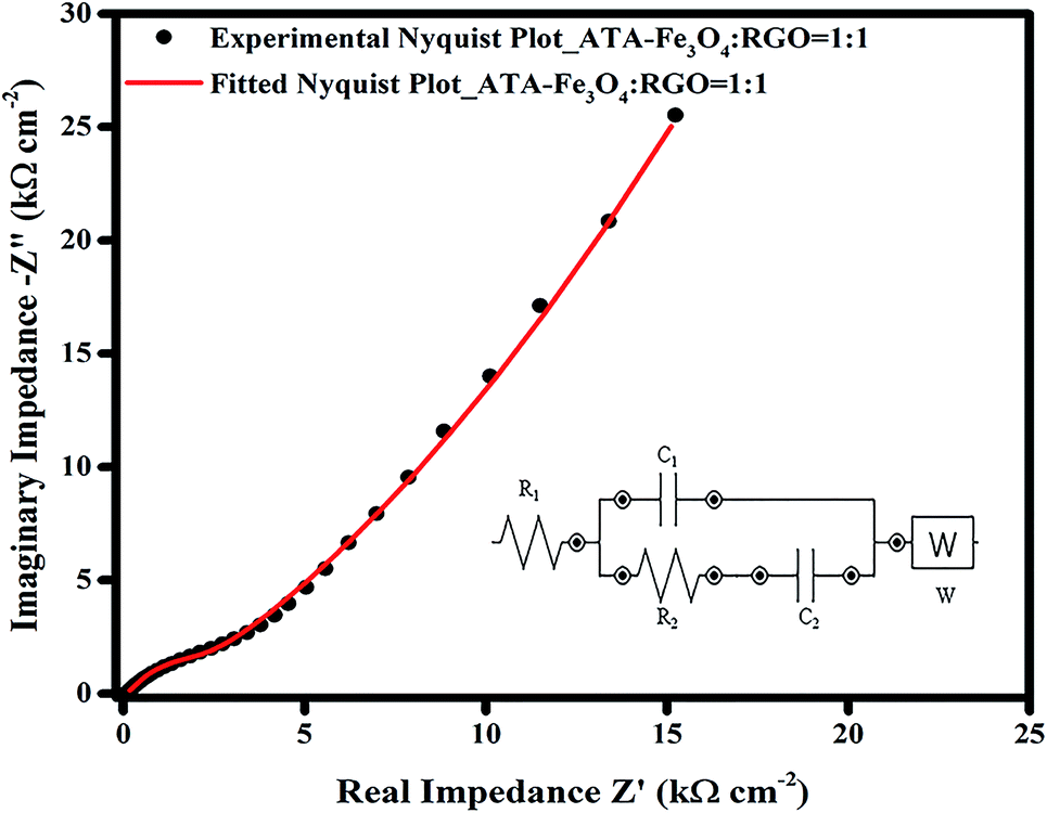 | ||
| Fig. 6 Nyquist plot of experimental and fitted impedance data for ATA–Fe3O4/RGO nanocomposite (ATA–Fe3O4:RGO = 1:1). Black dot represents the experimental data whereas the red line corresponds to the fitted data (inset shows the equivalent electrical circuit). | ||
The EIS data was further fitted using a model equivalent electrical circuit (inset of Fig. 6). The circuit corresponds to a resistance (R1), which includes solution resistance and contact resistance, a charge transfer resistance (R2) (occurring from faradic redox reactions), a double layer capacitance (C1) at the interface, a limit capacitance (C2)71 and a Warburg impedance (W). The fitted and the experimental data are plotted in Fig. 6 and it shows a residual χ2 value of 0.022 confirming an excellent fitting. The values of each component of the equivalent electrical circuit model was tabulated in Table S2 (ESI†). The small value of R1 (∼12 Ω) obtained from the fitting also confirms a better electrochemical performance of the supercapacitor electrode material. The change in the nature of the Nyquist plot with the increase in the cycling is also plotted (Fig. S12, ESI†), wherein the X-axis of 2nd and 3rd plots is shifted to enable clarity. The nature and the shape of all the curves remain similar, which suggests good electrochemical performance and long term electrode stability.33,54 Only the magnitude of charge transfer resistance is increased slightly,72 which may obstruct ion transfer resulting in decrease in overall capacitance. The increase in R2 values may occur, as discussed earlier, due to the agglomeration of iron oxide particles during charging.73 This is consistent with our finding from the charge–discharge analysis where 14% of capacitance loss is observed after 5000 cycles.
The long term charging discharging analysis and impedance spectroscopy reflects that there are no substantial morphological and/or structural changes in the nanocomposites. However, for further confirmation FTIR and SEM analysis were performed before and after the cycling.
To investigate any alteration in the functional groups, we have carried out FTIR analysis of the sample before and after cycling (Fig. S13, ESI†) we can clearly infer that there is no significant change in the transmission spectra; indicative of no structural alteration. Both spectra contain the identical bands. The presence of –CONH linkage (∼1570 cm−1) after the cycling clearly suggest that ATA is still attached to the nanoparticles surface and the coating is not damaged (Fig. S13†). To spot any significant morphological change, SEM analysis was performed on the ATA–Fe3O4:RGO = 1:1 sample before and after the charging/discharging cycling experiment. The SEM images are shown in Fig. S14 (ESI†). From the figure, it is evident that there is no substantial change in the microstructure. Apart from agglomeration in few areas the nanoparticles remain intact, which further confirms the long-term stability of the nanocomposites.
4. Conclusions
In summary, a novel ATA–Fe3O4/RGO nanocomposite was synthesized. The surface coating of Fe3O4 by ATA not only provides stability to nanoparticles but also endows it with faster charge transport via anchoring with the residual functional groups of the RGO. The nanocomposite showed significantly higher capacitance values than the pristine Fe3O4 and RGO components. At the optimized Fe3O4/RGO ratio (1:1), concentration (1 mg ml−1) and loading (12 μg), a maximum capacitance of 576 F g−1 was achieved (at 10 mV s−1). Likewise, a high energy density of 75 W h kg−1 (at 6 A g−1) was also achieved at the same ratio and concentration. The ATA–Fe3O4/RGO system displays promising long term stability with the retention of 86% of the capacitance even after 5000 cycles. These results reveal the potential use of ATA–Fe3O4/RGO nanocomposite for high performance electrochemical energy storage applications.
Acknowledgements
Gourav Bhattacharya, Ravi Kant Upadhyay and Sujit Deshmukh are indebted to Shiv Nadar University for providing scholarship. The authors are also thankful to Prof. Subhasis Ghosh, School of Physical Sciences, Jawaharlal Nehru University, for his support and useful discussions.References
- P. Simon and Y. Gogotsi, Nat. Mater., 2008, 7, 845–854 CrossRef CAS PubMed.
- T. Y. Wei, C. H. Chen, H. C. Chien, S. Y. Lu and C. C. Hu, Adv. Mater., 2010, 22, 347–351 CrossRef CAS PubMed.
- M. F. El-Kady and R. B. Kaner, Nat. Commun., 2013, 4, 1475 CrossRef PubMed.
- X. Yu, B. Lu and Z. Xu, Adv. Mater., 2014, 26, 1044–1051 CrossRef CAS PubMed.
- L. L. Zhang and X. Zhao, Chem. Soc. Rev., 2009, 38, 2520–2531 RSC.
- F. Su and M. Miao, Nanotechnology, 2014, 25, 135401 CrossRef PubMed.
- Q. Yang, Z. Lu, Z. Chang, W. Zhu, J. Sun, J. Liu, X. Sun and X. Duan, RSC Adv., 2012, 2, 1663–1668 RSC.
- S. Senthilkumar, R. K. Selvan, N. Ponpandian and J. Melo, RSC Adv., 2012, 2, 8937–8940 RSC.
- K. S. Ryu, K. M. Kim, N.-G. Park, Y. J. Park and S. H. Chang, J. Power Sources, 2002, 103, 305–309 CrossRef CAS.
- T. Gujar, V. Shinde, C. Lokhande, W.-Y. Kim, K.-D. Jung and O.-S. Joo, Electrochem. Commun., 2007, 9, 504–510 CrossRef CAS.
- V. Ganesh, S. Pitchumani and V. Lakshminarayanan, J. Power Sources, 2006, 158, 1523–1532 CrossRef CAS.
- W. Yu, B. Li and S. Ding, Nanotechnology, 2016, 27, 075605 CrossRef CAS PubMed.
- F. Li, J. Song, H. Yang, S. Gan, Q. Zhang, D. Han, A. Ivaska and L. Niu, Nanotechnology, 2009, 20, 455602 CrossRef PubMed.
- X. Zhang, H. Zhang, C. Li, K. Wang, X. Sun and Y. Ma, RSC Adv., 2014, 4, 45862–45884 RSC.
- J. A. Davis, R. O. James and J. O. Leckie, J. Colloid Interface Sci., 1978, 63, 480–499 CrossRef CAS.
- M. Kim, C. Lee and J. Jang, Adv. Funct. Mater., 2014, 24, 2489–2499 CrossRef CAS.
- C. X. Guo and C. M. Li, Energy Environ. Sci., 2011, 4, 4504–4507 CAS.
- L. L. Zhang, R. Zhou and X. Zhao, J. Mater. Chem., 2010, 20, 5983–5992 RSC.
- J. Yan, Z. Fan, T. Wei, W. Qian, M. Zhang and F. Wei, Carbon, 2010, 48, 3825–3833 CrossRef CAS.
- Y. Zhu, S. Murali, M. D. Stoller, K. Ganesh, W. Cai, P. J. Ferreira, A. Pirkle, R. M. Wallace, K. A. Cychosz and M. Thommes, Science, 2011, 332, 1537–1541 CrossRef CAS PubMed.
- X.-h. Xia, J.-p. Tu, X.-l. Wang, C.-d. Gu and X.-b. Zhao, J. Mater. Chem., 2011, 21, 671–679 RSC.
- B. Conway and E. Gileadi, Trans. Faraday Soc., 1962, 58, 2493–2509 RSC.
- P. J. Hall, M. Mirzaeian, S. I. Fletcher, F. B. Sillars, A. J. Rennie, G. O. Shitta-Bey, G. Wilson, A. Cruden and R. Carter, Energy Environ. Sci., 2010, 3, 1238–1251 CAS.
- M. Zhi, C. Xiang, J. Li, M. Li and N. Wu, Nanoscale, 2013, 5, 72–88 RSC.
- R. Ning, J. Tian, A. M. Asiri, A. H. Qusti, A. O. Al-Youbi and X. Sun, Langmuir, 2013, 29, 13146–13151 CrossRef CAS PubMed.
- Q. Chu, J. Du, W. Lu, G. Chang, Z. Xing, H. Li, C. Ge, L. Wang, Y. Luo and A. M. Asiri, ChemPlusChem, 2012, 77, 872–876 CrossRef CAS.
- S. Liu, J. Tian, L. Wang, Y. Luo and X. Sun, Catal. Sci. Technol., 2012, 2, 339–344 CAS.
- P. M. Hallam, M. Gómez-Mingot, D. K. Kampouris and C. E. Banks, RSC Adv., 2012, 2, 6672–6679 RSC.
- X. Du, C. Wang, M. Chen, Y. Jiao and J. Wang, J. Phys. Chem. C, 2009, 113, 2643–2646 CAS.
- Y.-H. Kim and S.-J. Park, Curr. Appl. Phys., 2011, 11, 462–466 CrossRef.
- D. Guan, Z. Gao, W. Yang, J. Wang, Y. Yuan, B. Wang, M. Zhang and L. Liu, Mater. Sci. Eng., B, 2013, 178, 736–743 CrossRef CAS.
- N. Soin, S. S. Roy, S. K. Mitra, T. Thundat and J. A. McLaughlin, J. Mater. Chem., 2012, 22, 14944–14950 RSC.
- W. Shi, J. Zhu, D. H. Sim, Y. Y. Tay, Z. Lu, X. Zhang, Y. Sharma, M. Srinivasan, H. Zhang and H. H. Hng, J. Mater. Chem., 2011, 21, 3422–3427 RSC.
- C. Liu, Z. Yu, D. Neff, A. Zhamu and B. Z. Jang, Nano Lett., 2010, 10, 4863–4868 CrossRef CAS PubMed.
- L. Wang, Y. Liu, T. Lai, H. Liang, Z. Li, Z. Mei, F. Zhang, A. Kuznetsovd and X. Duab, RSC Adv., 2013, 3, 13059–13084 RSC.
- T. Kuila, P. Khanra, N. H. Kim, S. K. Choi, H. J. Yun and J. H. Lee, Nanotechnology, 2013, 24, 365706 CrossRef PubMed.
- D. Maity, G. Zoppellaro, V. Sedenkova, J. Tucek, K. Safarova, K. Polakova, K. Tomankova, C. Diwoky, R. Stollberger and L. Machala, Chem. Commun., 2012, 48, 11398–11400 RSC.
- J. Tian, R. Ning, Q. Liu, A. M. Asiri, A. O. Al-Youbi and X. Sun, ACS Appl. Mater. Interfaces, 2014, 6, 1011–1017 CAS.
- J. Yan, Z. Fan, W. Sun, G. Ning, T. Wei, Q. Zhang, R. Zhang, L. Zhi and F. Wei, Adv. Funct. Mater., 2012, 22, 2632–2641 CrossRef CAS.
- A. K. Das, M. Srivastav, R. K. Layek, M. E. Uddin, D. Jung, N. H. Kim and J. H. Lee, J. Mater. Chem. A, 2014, 2, 1332–1340 CAS.
- M. E. Uddin, R. K. Layek, N. H. Kim, D. Hui and J. H. Lee, Composites, Part B, 2015, 80, 238–245 CrossRef CAS.
- S. Stankovich, D. A. Dikin, R. D. Piner, K. A. Kohlhaas, A. Kleinhammes, Y. Jia, Y. Wu, S. T. Nguyen and R. S. Ruoff, Carbon, 2007, 45, 1558–1565 CrossRef CAS.
- S. Perumbilavil, P. Sankar, T. P. Rose and R. Philip, Appl. Phys. Lett., 2015, 107, 051104 CrossRef.
- M. Kurihara and H. Nishihara, Coord. Chem. Rev., 2002, 226, 125–135 CrossRef CAS.
- M. G. Bramucci, C. M. McCutchen, V. Nagarajan and S. M. Thomas, US Pat., No. 6187569, 13-February-2001.
- V. W.-W. Yam, C.-C. Ko and N. Zhu, J. Am. Chem. Soc., 2004, 126, 12734–12735 CrossRef CAS PubMed.
- R. Liang, L. Shen, F. Jing, W. Wu, N. Qin, R. Lin and L. Wu, Appl. Catal., B, 2015, 162, 245–251 CrossRef CAS.
- H.-Q. Li, Y.-G. Wang, C.-X. Wang and Y.-Y. Xia, J. Power Sources, 2008, 185, 1557–1562 CrossRef CAS.
- M. D. Stoller, S. Park, Y. Zhu, J. An and R. S. Ruoff, Nano Lett., 2008, 8, 3498–3502 CrossRef CAS PubMed.
- C. Vix-Guterl, E. Frackowiak, K. Jurewicz, M. Friebe, J. Parmentier and F. Béguin, Carbon, 2005, 43, 1293–1302 CrossRef CAS.
- K. Lee, S. Deng, H. Fan, S. Mhaisalkar, H. Tan, E. Tok, K. Loh, W. Chin and C. Sow, Nanoscale, 2012, 4, 2958–2961 RSC.
- J. Cornil, D. Beljonne, J. P. Calbert and J. L. Brédas, Adv. Mater., 2001, 13, 1053–1067 CrossRef CAS.
- G. Yu, L. Hu, N. Liu, H. Wang, M. Vosgueritchian, Y. Yang, Y. Cui and Z. Bao, Nano Lett., 2011, 11, 4438–4442 CrossRef CAS PubMed.
- B. G. Choi, M. Yang, W. H. Hong, J. W. Choi and Y. S. Huh, ACS Nano, 2012, 6, 4020–4028 CrossRef CAS PubMed.
- L. Zhang, F. Zhang, X. Yang, G. Long, Y. Wu, T. Zhang, K. Leng, Y. Huang, Y. Ma and A. Yu, Sci. Rep., 2013, 3, 1408 Search PubMed.
- F. He, J. Fan, D. Ma, L. Zhang, C. Leung and H. L. Chan, Carbon, 2010, 48, 3139–3144 CrossRef CAS.
- P. T. Yin, T.-H. Kim, J.-W. Choi and K.-B. Lee, Phys. Chem. Chem. Phys., 2013, 15, 12785–12799 RSC.
- T. Liu, W. Pell and B. Conway, Electrochim. Acta, 1997, 42, 3541–3552 CrossRef CAS.
- B. Qiu, Q. Li, B. Shen, M. Xing and J. Zhang, Appl. Catal., B, 2016, 183, 216–223 CrossRef CAS.
- Z. Chen, Q. Zhang, L. Huang, R. Li, W. Li, G. Xu and H. Cheng, J. Phys. Chem. C, 2014, 118, 21244–21249 CAS.
- L. Yin, J. Wang, F. Lin, J. Yang and Y. Nuli, Energy Environ. Sci., 2012, 5, 6966–6972 CAS.
- J. R. Macdonald, Ann. Biomed. Eng., 1992, 20, 289–305 CrossRef CAS PubMed.
- Y. Wang, Z. Shi, Y. Huang, Y. Ma, C. Wang, M. Chen and Y. Chen, J. Phys. Chem. C, 2009, 113, 13103–13107 CAS.
- Z. Niu, W. Zhou, J. Chen, G. Feng, H. Li, W. Ma, J. Li, H. Dong, Y. Ren and D. Zhao, Energy Environ. Sci., 2011, 4, 1440–1446 CAS.
- Q. Cheng, J. Tang, J. Ma, H. Zhang, N. Shinya and L.-C. Qin, Carbon, 2011, 49, 2917–2925 CrossRef CAS.
- D. Zhang, X. Zhang, Y. Chen, P. Yu, C. Wang and Y. Ma, J. Power Sources, 2011, 196, 5990–5996 CrossRef CAS.
- Y.-R. Nian and H. Teng, J. Electrochem. Soc., 2002, 149, A1008–A1014 CrossRef CAS.
- C. XianáGuo and C. MingáLi, Dalton Trans., 2011, 40, 6388–6391 RSC.
- J. Xu, K. Wang, S.-Z. Zu, B.-H. Han and Z. Wei, ACS Nano, 2010, 4, 5019–5026 CrossRef CAS PubMed.
- C. Arbizzani, M. Mastragostino and L. Meneghello, Electrochim. Acta, 1996, 41, 21–26 CrossRef CAS.
- A. Di Fabio, A. Giorgi, M. Mastragostino and F. Soavi, J. Electrochem. Soc., 2001, 148, A845–A850 CrossRef CAS.
- T. Qi, J. Jiang, H. Chen, H. Wan, L. Miao and L. Zhang, Electrochim. Acta, 2013, 114, 674–680 CrossRef CAS.
- C.-Y. Chen, C.-Y. Fan, M.-T. Lee and J.-K. Chang, J. Mater. Chem., 2012, 22, 7697–7700 RSC.
Footnote |
| † Electronic supplementary information (ESI) available. See DOI: 10.1039/c6ra25630a |
| This journal is © The Royal Society of Chemistry 2017 |