 Open Access Article
Creative Commons Attribution 3.0 Unported Licence
Stretchable electromagnetic-interference shielding materials made of a long single-walled carbon-nanotube–elastomer composite†
Yuto Kato *a,
Masahiro Horibea,
Seisuke Atab,
Takeo Yamadab and
Kenji Hatab
aResearch Institute for Physical Measurement, National Institute of Advanced Industrial Science and Technology (AIST), 1-1-1 Umezono, Tsukuba, Ibaraki 305-8568, Japan. E-mail: y-katou@aist.go.jp; Fax: +81-29-861-4177; Tel: +81-29-861-3541
bCNT-Application Research Center, National Institute of Advanced Industrial Science and Technology (AIST), 1-1-1 Higashi, Tsukuba, Ibaraki 305-8565, Japan
First published on 9th February 2017
Abstract
By using long single-walled carbon nanotubes that possess a high aspect ratio and small diameter as fillers, we introduced electromagnetic interference (EMI) shielding to a fluorinated rubber without hardening and embrittling it. A sheet of this material with a thickness of 0.2 mm could decrease more than 90% of the strength of incident electromagnetic waves at microwave frequencies. Further, this material has a sufficient flexibility, which enables it to elongate to double its original length without any cracking, and has a higher mechanical strength than commercialized generic stocking (3.1 times the maximum tensile stress and 2.4 times the tear strength). Therefore, this material is useful for flexible and stretchable EMI shielding sheets that can wrap an arbitrarily shaped radiating object. This feature can be attributed to the fact that the carbon nanotubes could induce EMI shielding at a low loading level (only 1 wt%) without breaking the structure of the rubber matrix.
Introduction
Materials for electromagnetic interference (EMI) shielding are used in all electronic devices to prevent the penetration of electromagnetic waves emitted from radiation sources. As electromagnetic radiation tends to interfere with electronics, which could lead to abnormal operation, EMI shielding is needed for both electronics and radiation sources to meet the current demands for high-reliability electronics. For wireless communication devices, EMI shielding is also required to eliminate the risk of information leakage by electromagnetic emission from telecommunication equipment. For EMI shielding materials, metals such as copper or aluminum have typically been used because these high-conductivity materials contribute to a high EMI shielding efficiency (SE), where the EMI SE is defined as the ratio of the transmitted power density to the incident power density.The evolution of electronics, however, has led to the emergence of new demands for EMI shielding materials that cannot be met by metal-based EMI shielding materials. The most prominent example is in flexible electronics, where flexible and stretchable devices such as wearable electronics, smart clothing, flexible displays, stretchable sensors, and implantable devices have been intensively studied to realize soft and human-friendly applications. In order to shield stretchable devices that can change their shape, EMI shielding materials should also be stretchable to wrap around the complex curvilinear shapes of stretchable devices conformally and to have the capability to absorb a large level of strain without a significant degradation in their EMI SE. Metal-based EMI shielding materials are not applicable owing to their low flexibility and stretchability.
An elastomer such as rubber has a high flexibility and stretchability but is not able to be used as an EMI shielding material because it is insulating. Instead, it is made to be conductive by combining it with an electrically conducting filler such as carbon black (CB),1–3 carbon fiber (CF),1,4 and graphite.5 For any filler, the EMI SE increases as the filling rate in the composite increases. However, it is well known that rubbers harden and become brittle as the filling rate of the fillers increases because of the poor filler–matrix mechanical bonding, resulting in reductions in the flexibility and stretchability of the composites.6,7 Therefore, it is indispensable to make an elastomer highly conductive with a low loading level without any degradation in its flexibility to realize flexible and stretchable EMI shielding materials.
To this end, fillers with high aspect ratios are advantageous over short fillers because a higher aspect ratio leads to a lower critical filling rate (known as the percolation threshold) for forming a conductive network in the rubber matrix,8–10 which results in significant EMI shielding performance. Carbon nanotubes (CNTs) are candidates for conductive fillers with high aspect ratios.
Although there have been many works on CNT/polymer composites for realizing EMI shielding materials,11–14 only a limited number of reports studied CNT-based stretchable EMI shielding materials. For example, Kim et al.6 prepared a highly conductive elastomer with high EMI shielding by loading selectively aligned multiwalled CNTs (MWCNTs) (diameter: 100–200 nm) into ethylene propylene diene rubber (EPDM), but a high loading (30 wt%) was necessary to obtain sufficient shielding. Chen et al.15 reported a flexible and conductive material comprising polydimethylsiloxane (PDMS) and MWCNTs (diameter: 10–20 nm, length: 5–20 μm) carbon aerogel (MCA) reinforced with a quartz fiber cloth (QFC). The EMI SE of their material reached 20 dB (the EMI SE level needed for commercial application) with only 2 wt% MWCNTs; however, their material broke at a strain less than 5%. Fletcher et al.16 fabricated an elastomer nanocomposite consisting of MWCNTs in a fluorocarbon polymer and reported EMI SEs of approximately 50 dB for an MWCNT filler loading of 12 wt% and approximately 20 dB for a loading of 6 wt%. However, their measured samples were rather thick (3.8 mm). To reduce the size and weight of electronic devices, the EMI shielding materials that wrap these devices should also be thin. Because the EMI SE in decibels is roughly proportional to the thickness, they reported that the EMI SE for an MWCNT filler loading of 12 wt% was approximately 15 dB when the thickness was 0.8 mm.16
As shown, many of the studies in the literature have utilized MWCNTs as conductive fillers. Because the aspect ratio of single-walled CNTs (SWCNTs) is much higher than that of MWCNTs, SWCNT/rubber composites are expected to realize an EMI shielding material with a low loading level and meet the three conflicting demands, i.e., a sufficient EMI SE (>20 dB), a thin sheet (<0.5 mm), and a desirable mechanical flexibility.
Results and discussion
In this work, we used long single-walled CNTs with an exceptionally high aspect ratio (diameter: 3 nm, length: >1 mm), denoted as “super-growth” CNTs (SG-CNTs),17 as conductive fillers. The EMI SE of the SG-CNT/fluorinated rubber composite sheet with a thickness of 0.2 mm reached more than 20 dB with a loading of only 1 wt%, which corresponds that more than 90% of the incident electromagnetic waves have been attenuated by the sheet. Further, our material has a sufficient flexibility, i.e., it could be stretched to double its original length without any cracking and has a higher mechanical strength than commercialized generic stocking (3.1 times the maximum tensile stress and 2.4 times the tear strength). Therefore, it can be applied to EMI problems for a wide range of electronic devices, including stretchable devices, even if they have complex curvilinear shapes or change their shapes at large levels.SG-CNTs were synthesized by efficient chemical vapor deposition (CVD), where the activity and lifetime of the catalysts were enhanced by water.17 Water-assisted CVD results in the growth of dense and vertically aligned SWCNT forests with a millimeter-scale height, near-ideal specific surface area (1300 m2 g−1), and high carbon purity (>99.98%) after a 10 min growth time. Because of these exceptional properties, SG-CNTs have expanded the possibilities of CNTs for a wide range of applications such as supercapacitors,18,19 actuators,20 blackbody absorbers,21 and elastic conductors.22,23 Elastic conductors using SG-CNTs have been utilized to realize stretchable devices such as flexible displays24 and strain sensors.25 We expect that elastic conductors will also realize stretchable EMI shielding materials because the millimeter-scale-height SG-CNTs with an exceptionally high aspect ratio induce EMI shielding in the rubber matrix at a low loading level.
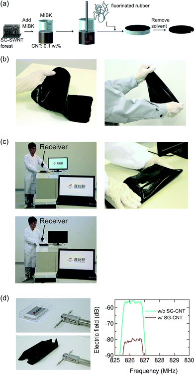
SG-CNT forests were removed from the growth substrate and suspended in methyl isobutyl ketone (MIBK) by a high-pressure jet-milling homogenizer (60 MPa, nanojet pal, JN10, Jokoh) (Fig. 1a). From this suspension, the SG-CNT/elastomer composites were fabricated by adding fluorinated rubber (Daiel-G912, Daikin), stirring with a magnetic tip (25 °C for 16 h), casting, and finally drying for the removal of MIBK (120 °C for 6 h in vacuum). When we fabricated a thin sheet (<0.5 mm), we used an ultrasonic homogenizer (50 W, 20 ± 1 kHz, 12 h) in addition to jet-milling. The length of SG-CNTs after dispersion was reported to be approximately 0.4 μm based on AFM observations.26 We could easily fabricate large-scale films with an excellent uniformity, as demonstrated by the A4-size (20 cm × 30 cm) composite sheet (Fig. 1b).
A thin sheet of the obtained CNT/fluorinated composite with a thickness of 0.2 mm has a high EMI SE > 20 dB (>90% shielding) and a stretchability greater than 100%. Therefore, it can be used as a stretchable EMI shielding material applicable to a wide variety of EMI problems in many aspects of daily life where the CNT-based stretchable EMI shielding material could wrap an arbitrarily shaped radiating object.
First, we demonstrated its usefulness without any ambiguity by using a wireless video transmission system (Fig. 1c). To visualize electromagnetic waves, we observed a video on a display that was transmitted from a notebook computer by 60 GHz millimeter-waves (Wireless HDMI), where the receiver and transmitter (HDMI-WKIT, PLANEX) were connected to a display and notebook, respectively, for transmitting the video. Immediately after wrapping the receiver with the CNT-based stretchable EMI shielding material, the video on a display disappeared, which unambiguously showed that the CNT-based stretchable EMI shielding material could shield electromagnetic waves at millimeter-wave frequencies and stop the transmission.
Further, we demonstrated that the CNT-based stretchable EMI shielding material could eliminate the risk of information leakage by preventing electromagnetic emission from telecommunication equipment. Many electronic devices such as computers, printers, home electrical appliances, and industrial equipment have the ability to connect to the internet wirelessly. This means that more personal information and business data exist in the air, which might be monitored by hackers and enemies from the outside by detecting electromagnetic emissions. In Fig. 1d, a smartphone (iPhone 5, Apple) represented a device that emitted electromagnetic waves including information, and a polystyrene box represented the walls of a room. When electromagnetic waves penetrated the box, the emissions from the smartphone in the 800 MHz frequency band were detected by a dipole antenna placed outside the box. After wrapping the polystyrene box with the CNT-based stretchable EMI shielding material, the emissions were significantly reduced by more than 20 dB (>90% shielding). Therefore, the CNT-based stretchable EMI shielding material can provide safe telecommunication in a closed room by covering the complex curvilinear shapes of room walls.
In both demonstrations, the receiver and smartphone were wrapped with the CNT-based stretchable EMI shielding material without any gap by utilizing its high flexibility and stretchability, resulting in effective EMI shielding. Note that traditional metal-based shielding materials cannot be applied to both demonstrations because of their low flexibility and stretchability.
The frequency bands shielded by the CNT-based stretchable EMI shielding material were the 60 GHz millimeter-wave and 800 MHz frequency bands for the former and latter demonstrations, respectively. This means that our material is applicable to many types of applications utilizing electromagnetic waves in a wide range of frequencies.
Next, we demonstrate that the CNT-based stretchable EMI shielding material is superior to traditional conductive rubber composites on the basis of its EMI shielding and elastic properties. We compared the SG-CNT-based stretchable EMI shielding material (SG, thickness: 0.2 mm) with fluorinated rubber composites with different fillers: 20 wt% loading of CF (CF, thickness: 0.5 mm) and 30 wt% loading of CB (CB, thickness: 0.3 mm). Note that the high fillings are necessary for the CF and CB to make the rubbers conductive owing to the much lower aspect ratios of the CF and CB than that of the SG-CNTs. In addition, we also compared with a commercialized conductive silicone rubber (Q, thickness: 1.0 mm; Fuso Rubber).
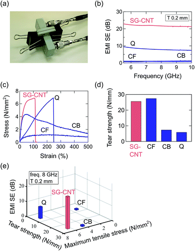
To demonstrate the superiority of the CNT-based stretchable EMI shielding material on the basis of its EMI shielding properties, we measured the EMI SE from 5.5 to 10 GHz by using the ASTM D4935 standard method for the SG, CF, CB, and Q samples. Here, a sample was held by two coaxial-to-waveguide adapters, which connect a 7 mm coaxial line and a WR-137 waveguide used for C-band frequencies (Fig. 2a). The transmittance between the two adapters without a sample (Sempty21) and that when a sample is inserted (Smat21) were measured, and the SE was calculated with the following equation:
SE = −20![[thin space (1/6-em)]](https://www.rsc.org/images/entities/char_2009.gif) log10|Smat21/Sempty21| (dB). log10|Smat21/Sempty21| (dB).
| (1) |
Because the EMI SE increases as the thickness of the sample increase, we should compare the EMI SEs of samples with the same thickness for all materials. However, it was difficult to accurately control the thickness during the fabrication process; therefore, we normalized the EMI SE, where the measured EMI SE was converted to that for a sample of the same material with a thickness of 0.2 mm (equal to the thickness of the SG-CNT sample) by using eqn (2) to (4). The results are summarized in Fig. 2b. The EMI SE of the SG sample was sufficiently high (over 20 dB; 90% shielding) and was much higher than that of the commercialized product (Q). The fillers with low aspect ratios, CF and CB, did not introduce sufficient shielding, even though they were added at more than 20 wt%. Because of the exceptionally high aspect ratio of the SG-CNTs, we realized a thin sheet (0.2 mm) of EMI shielding material with the required EMI SE level for commercial applications (20 dB) with a loading of only 1 wt%.
Further, we demonstrated that the CNT-based stretchable EMI shielding material had sufficient elastic properties comparable to traditional rubber composites. Fig. 2c shows the stress–strain properties obtained using the ASTM D412 standard method for the SG, CF, CB, and Q samples. We confirmed that the SG sample had a sufficient flexibility such that it could stretch to double its original length without any cracks. The maximum tensile stress of the SG sample (6.4 N mm−2) was comparable to that of the commercialized one (Q, 6.9 N mm−2), whereas those of the rubbers with high fillings of CF and CB were much lower because the rubbers hardened and became brittle when incorporating the conductive fillers at high loading levels. In addition, we investigated the mechanical strength by measuring the tear strength obtained using the ASTM D624 standard method (Fig. 2d) for all four materials. The highest tear strength was obtained for the CF sample; however, a comparable tear strength (25.6 N mm−1) was achieved by the SG sample. Therefore, we conclude that the CNT-based stretchable EMI shielding material has comparable or superior elastic properties to traditional rubber composites on the basis of both its stretchability (maximum tensile stress) and mechanical strength (tear strength).
Comparisons of the EMI shielding and elastic properties are summarized in Fig. 2e. The CNT-based stretchable EMI shielding material was superior to the traditional conductive rubbers in terms of the EMI shielding, stretchability, and mechanical strength (especially the EMI shielding property). Therefore, we believe that our approach realizes a flexible and stretchable EMI shielding sheet.
For practical applications, the mechanical durability, which describes the ability of a material to bear many strain cycles, is a fundamental and challenging requirement for a stretchable EMI shielding material. During duration testing, the CNT-based stretchable EMI shielding material was exposed to 1 million loading–unloading strain cycles at 10% strain (Fig. 3a), where the EMI SE before the strain cycles and after 1, 5, 10, 50, 100, 500, 1000, and 1 million cycles were measured by using the ASTM D4935 standard method (Fig. 3b). The EMI SE maintained the level necessary for commercial applications (20 dB; 90% shielding), even after 1 million cycles. Therefore, we conclude that our approach provides a practical stretchable EMI shielding material.
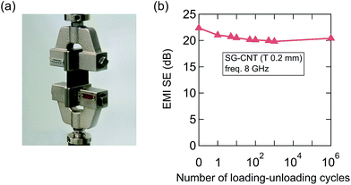 | ||
| Fig. 3 (a) Photograph of the duration testing machine. (b) EMI SE of the CNT-based stretchable EMI shielding material plotted versus the number of loading–unloading cycles. | ||
To understand the reason why the CNT-based stretchable EMI shielding material has a sufficient EMI SE at a loading of only 1 wt%, we examined the relationships between the EMI SE and the filling rate of the conductive fillers for three different types of CNTs. We compared SG-CNTs (1 wall, diameter: 3 nm, length: >1 mm) with commercially available CNTs including Nanocyl (∼5 walls, diameter: 9.5 nm, length: 50 μm) and C-Nano (∼10 walls, diameter: 11 nm, length: 50 μm). For each filler, we measured three samples with different filling rates (1, 2, and 5 wt%). Fig. 4a shows the EMI SE at 8 GHz plotted versus the filling rate. The EMI SE increases as the filling rate increases for all CNT fillers because conductive networks were formed by increasing the filling rate of the conductive fillers. Comparing results for the same filling rate, the SG and C-Nano samples have the highest and lowest EMI SEs, respectively, among the three CNT fillers, which can be attributed to the fact the SG-CNTs and C-Nano have highest and lowest aspect ratios, respectively, among the three CNTs. By using SG-CNT with an exceptionally high aspect ratio, we realized an EMI shielding material with a loading of only 1 wt%.
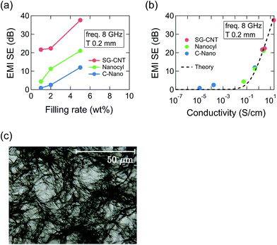 | ||
| Fig. 4 EMI SEs of CNT composites (SG, Nanocyl, and C-Nano) plotted versus the (a) filling rate and (b) conductivity. (c) Optical microscope image of the 1 wt% SG-CNT/fluorinated rubber composite. | ||
To clarify the origin of the relation between the aspect ratio and the EMI SE, we examined the mechanism of EMI shielding. Fig. 4b shows the EMI SE at 8 GHz for each CNT filler (1, 2, and 5 wt%) plotted versus the conductivity measured by a four-point probe electrical tester. We can confirm that the EMI SE increases as the conductivity increases, and a conductivity greater than 2 S cm−1 is required to realize an EMI SE greater than 20 dB (90% shielding). Note that the results for different CNT fillers follow the same trend (see dashed line), which can be explained by the transmission line theory of electromagnetic waves as follows.
By using transmission line theory, the EMI SE measured by the ASTM D4935 standard method is given by
 | (2) |
 | (3) |
 is the complex relative permittivity of the sample; and
  is the imaginary unit. For high-conductivity materials,
  is approximated by
 | (4) |
This feature was investigated for our approach by internal structural observation. A solution of 1 wt% SG-CNTs/fluorinated rubber/MIBK was cast onto a glass slide and observed by an optical microscope. Because of the exceptionally high aspect ratio of the SG-CNTs, they form a fibrous structure interconnected to each other at a low loading, which creates a conductive network in the rubber matrix and leads to a high EMI SE. We believe that the filling rate needed to realize an EMI shielding material is lower than that needed to harden and embrittle the rubber in our approach. As a result, a stretchable EMI shielding material having a sufficient EMI SE, flexibility, and stretchability is realized.
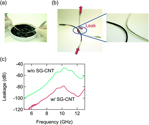
Our approach can be expanded to coating process. Since the base material of this study, a fluorinated rubber, is used in the cable harnesses of vehicles, we demonstrated the EMI shielding of cables by dip-coating with an SG-CNT/fluorinated rubber/MIBK solution. Two coaxial cables were prepared with small slits in their outer conductors to induce the leakage of electromagnetic waves, and the leakage between them before and after coating the SG-CNT/fluorinated rubber composite on one cable was measured (Fig. 5). We confirmed a significant reduction in the leakage by approximately 20 dB (90% shielding) with a coating having a thickness of only 90 μm. There have been reports about EMI shielding films fabricated by coating processes in which CNTs27,28 and graphene28 were used as conductive fillers. However, there have been no studies that fabricated stretchable EMI shielding films by coating thus far. We conclude that the CNT-based stretchable EMI shielding material can suppress electromagnetic waves by conformal coating around the complex curvilinear shapes of radiating objects including devices, cables, and connectors.
Conclusions
We developed a flexible and stretchable EMI shielding material by using SG-CNTs as fillers possessing a high aspect ratio and small diameter. At a low loading of SG-CNTs (1 wt%) in a fluorinated rubber, a high EMI SE (20 dB; 90% shielding) was introduced without hardening or embrittling the rubber. The EMI SE is maintained over 1 million loading–unloading strain cycles at 10% strain. The coating process is also available for our approach. We believe that the present study demonstrates an approach to realize a thin and stretchable EMI shielding material that suppresses electromagnetic emissions by wrapping or coating around the complex curvilinear shapes of radiating objects.Experimental section
Sample preparation
Vertically aligned SWNTs (forests) were synthesized in a fully automatic 1 inch tube furnace by water-assisted chemical vapor deposition, so-called “super-growth”, on a silicon substrate with a thin film iron catalyst (1 nm) supported on an alumina layer (10 nm) at 750 °C using ethylene as a carbon source with a parts per million (ppm) level of water as a catalyst enhancer and preserver.17 To compare with SG-CNT-based EMI shielding material, CF (Dialead K223HM, Mitsubishi Chemical) and CB (HAF, Tokai Carbon Co. Ltd)-based conductive rubbers were synthesized. Also, conductive silicone rubber was purchased from Fuso Rubber as a comparison. To compare SG-CNT fillers with other CNT fillers, Nanocyl-MWNT and C-Nano-MWNT were purchased from Nanocyl s.a. and CNano Technology Ltd, respectively.Shielding measurements
Electromagnetic interference shielding effectiveness (EMI-SE) from 5.5 to 10 GHz of the sheet samples were evaluated by using the ASTM D4935 standard method, where the sheets were held by two coaxial-to-waveguide adapters, and the transmittance was measured by using a vector network analyzer (E8364B, Keysight technologies).Electric-field strength measurements
Electric field strength radiated from a smartphone (iPhone 5, Apple) was measured by using a spectrum analyzer (FSV13, Rohde & Schwarz) with a dipole antenna as a probe.Leakage measurements
Leakage between two coaxial cables were evaluated by measuring the transmittance using a vector network analyzer (E8364B, Keysight technologies), where one port of each cable was connected to the instrument and the other was terminated by a load circuit.Elastic property measurements
Maximum tensile strengths and tear strengths were evaluated by using the ASTM D412 and ASTM D624 standard methods, respectively, where stress–strain curves of the sheet samples (40 mm in length, 2.0 mm in width) were measured by using an autograph (AG-IS, Shimadzu Co.) with 500 N load cell.Mechanical durability test
Duration testing was performed with a Micro-Servo (MMT101N, Shimadzu Co.).Conductivity measurements
Electrical conductivities of the nanotube sheets were measured by a four-prove DC current method with a low resistivity meter (MCP-T610, Mitsubishi Chemical Analytech Co., Ltd).Structure observation
Optical microscope (VHX-1000, KEYENCE Co.) was performed to observe the internal structures of the composite.References
- N. Das, D. Khastgir, T. Chaki and A. Chakraborty, Composites, Part A, 2000, 31, 1069 CrossRef.
- G. Mohanraj, T. Chaki, A. Chakraborty and D. Khastgir, Polym. Eng. Sci., 2006, 46, 1342 CAS.
- P. Ghosh and A. Chakrabarti, Eur. Polym. J., 2000, 36, 1043 CrossRef CAS.
- P. B. Jana, S. Chaudhuri, A. K. Pal and S. K. De, Polym. Eng. Sci., 1992, 32, 448 CAS.
- C. Morari, I. Balan, J. Pintea, E. Chitanu and I. Iordache, Progress In Electromagnetics Research M, 2011, 21, 93 CrossRef.
- Y. A. Kim, T. Hayashi, M. Endo, Y. Gotoh, N. Wada and J. Seiyama, Scr. Mater., 2006, 54, 31 CrossRef CAS.
- P. Annadurai, A. K. Mallick and D. K. Tripathy, J. Appl. Polym. Sci., 2002, 83, 145 CrossRef CAS.
- A. Celzard, E. McRae, C. Deleuze, M. Dufort, G. Furdin and J. F. Mareche, Phys. Rev. B: Condens. Matter Mater. Phys., 1996, 53, 6209 CrossRef CAS.
- J. Li, P. Ma, W. Chow, C. To, B. Tang and J.-K. Kim, Adv. Funct. Mater., 2007, 17, 3207 CrossRef CAS.
- S.-H. Yao, Z.-M. Dang, M.-J. Jiang, H.-P. Xu and J. Bai, Appl. Phys. Lett., 2007, 91, 212901 CrossRef.
- Y. Yang, M. C. Gupta, K. L. Dudley and R. W. Lawrence, Nano Lett., 2005, 5, 2131 CrossRef CAS PubMed.
- H. M. Kim, K. Kim, C. Y. Lee, J. Joo, S. J. Cho, H. S. Yoon, D. A. Pejakovic, J. W. Yoo and A. J. Epstein, Appl. Phys. Lett., 2004, 84, 589 CrossRef CAS.
- N. Li, Y. Huang, F. Du, X. He, X. Lin, H. Gao, Y. Ma, F. Li, Y. Chen and P. C. Eklund, Nano Lett., 2006, 6, 1141 CrossRef CAS PubMed.
- Y. Huang, N. Li, Y. Ma, F. Du, F. Li, X. He, X. Lin, H. Gao and Y. Chen, Carbon, 2007, 45, 1614 CrossRef CAS.
- M. Chen, L. Zhang, S. Duan, S. Jing, H. Jiang, M. Luo and C. Li, Nanoscale, 2014, 6, 3796 RSC.
- A. Fletcher, M. C. Gupta, K. L. Dudley and E. Vedeler, Compos. Sci. Technol., 2010, 70, 953 CrossRef CAS.
- K. Hata, D. N. Futaba, K. Mizuno, T. Namai, M. Yumura and S. Iijima, Science, 2004, 306, 1362 CrossRef CAS PubMed.
- A. Izadi-Najafabadi, S. Yasuda, K. Kobashi, T. Yamada, D. N. Futaba, H. Hatori, M. Yumura, S. Iijima and K. Hata, Adv. Mater., 2010, 22, E235 CrossRef CAS PubMed.
- T. Hiraoka, A. Izadi-Najafabadi, T. Yamada, D. N. Futaba, S. Yasuda, O. Tanaike, H. Hatori, M. Yumura, S. Iijima and K. Hata, Adv. Funct. Mater., 2010, 20, 422 CrossRef CAS.
- K. Mukai, K. Asaka, T. Sugino, K. Kiyohara, I. Takeuchi, N. Terasawa, D. N. Futaba, K. Hata, T. Fukushima and T. Aida, Adv. Mater., 2009, 21, 1582 CrossRef CAS.
- K. Mizuno, J. Ishii, H. Kishida, Y. Hayamizu, S. Yasuda, D. N. Futaba, M. Yumura and K. Hata, Proc. Natl. Acad. Sci. U. S. A., 2009, 106, 6044 CrossRef CAS PubMed.
- T. Sekitani, Y. Noguchi, K. Hata, T. Fukushima, T. Aida and T. Someya, Science, 2008, 321, 1468 CrossRef CAS PubMed.
- S. Ata, K. Kobashi, M. Yumura and K. Hata, Nano Lett., 2012, 12, 2710 CrossRef CAS PubMed.
- T. Sekitani, H. Nakajima, H. Maeda, T. Fukushima, T. Aida, K. Hata and T. Someya, Nat. Mater., 2009, 8, 494 CrossRef CAS PubMed.
- T. Yamada, Y. Hayamizu, Y. Yamamoto, Y. Yomogida, A. Izadi-Najafabadi, D. N. Futaba and K. Hata, Nat. Nanotechnol., 2011, 6, 296 CrossRef CAS PubMed.
- T. Morimoto, S.-K. Joung, T. Saito, D. N. Futaba, K. Hata and T. Okazaki, ACS Nano, 2014, 8, 9897 CrossRef CAS PubMed.
- L.-L. Wang, B.-K. Tay, K.-Y. See, Z. Sun, L.-K. Tan and D. Lua, Carbon, 2009, 47, 1905 CrossRef CAS.
- C. Acquarelli, A. Rinaldi, A. Tamburrano, G. D. Bellis, A. G. D'Aloia and M. S. Sarto, 2014 IEEE Int. Symp. Electromagn. Compat. [Proc.], 2014, p. 488 Search PubMed.
Footnote |
| † Electronic supplementary information (ESI) available: The electromagnetic shielding properties and mechanical properties for SG-CNT/fluorinated rubber composites (1, 2, and 5 wt%) and the fluorinated rubber. See DOI: 10.1039/c6ra25350d |
| This journal is © The Royal Society of Chemistry 2017 |

