 Open Access Article
Creative Commons Attribution 3.0 Unported Licence
High performance and tunable artificial muscle based on two-way shape memory polymer
J. Fan and
G. Li*
Department of Mechanical & Industrial Engineering, Louisiana State University, Baton Rouge, LA 70803, USA. E-mail: lguoqi1@lsu.edu
First published on 4th January 2017
Abstract
Artificial muscles, a class of bio-inspired actuators, have been investigated for decades. Recently, a remarkable breakthrough in artificial muscles was achieved by twisting then coiling polymeric fishing lines or sewing threads. Driven by the negative coefficient of thermal expansion (NCTE), the tensile actuation strain, which was about 4% in the precursor nylon 6,6 fiber, was magnified to about 34% in the muscle. However, the muscle is limited by its higher actuation temperature (up to 160 °C). Also, some applications such as soft robots require even larger actuation strain to maintain locomotion. In this study, chemically cross-linked poly(ethylene-co-vinyl acetate) (cPEVA) two-way shape memory polymer (2W-SMP) was synthesized, characterized, and processed into precursor fibers based on a solid solution approach. Artificial muscles were manufactured through twist insertion in the precursor fibers. It was found that the 2W-SMP fibers contract upon heating and expand upon cooling, similar to polymeric fibers with NCTE, but with lower actuation temperature and higher actuation strain. The cPEVA fiber, which has about 18% contraction when the temperature is increased from 20 °C to 67 °C, exhibits an actuation strain up to 68% in the muscle. It was also found that the muscle actuation is tunable, i.e., independent of its actuation history.
Introduction
Bio-inspired artificial muscles have become a rigorous scientific research field in recent decades.1–10 Many studies have been conducted in this research field, including biomimetic design,1–4 exploring new materials,11–19 theoretical modeling,20–25 and searching for new areas of applications.5,26–31 Among these related research areas, materials innovation takes a lead role. For the first generation of polymeric artificial muscles, McKibben actuators or pneumatic artificial muscles, appropriate rubbers were utilized.1,20,21,26,27 Within the material, a type of gas such as air was employed to supply the energetic source for the expansion and contraction of the rubber bladder. When electrical current or voltage was used as the driving energy, a conductive material was required. Subsequently, pure metals,16 dielectric elastomers,4 ferroelectric materials,13 liquid crystal elastomers (LECs),17 ionic polymer metal composites,14 and conducting polymers12 were utilized. However, each of them has certain limitations. For instance, dielectric elastomers and ferroelectric materials need a high driving voltage; the stiffness of LECs is low, and the cost is high. The limitations for conducting polymers and ionic polymer metal composites persist in their low reversibility. Later, carbon nanotube (CNT), an electrical conductor and mechanically strong material, attracted a lot of attention from scientists and engineers.7–9,18,19 Twisted and coiled CNT yarns have been processed into artificial muscles. However, the low translation or tension actuation strain (1.3%) is their major limitation.9A recent breakthrough in polymeric artificial muscles has been the discovery of twisted then coiled low-cost fishing lines and sewing threads.32 The twisting then coiling manipulation of precursor polymeric fibers gives rise to muscles with outstanding performances, including energy densities as high as 2.63 kJ kg−1, power densities over 5.3 kW kg−1 and strokes up to 49%. Most recently, a number of studies have been conducted on this class of muscles, including testing and characterization methods,33–35 mathematical modeling,22–25 and applications such as robotics,31 morphing airplanes and vehicles,28 and self-healing systems.29,30 It is revealed that the negative coefficient of thermal expansion (NCTE) in the fiber axial direction plays a critical role in muscle actuation.25,32 However, for the several typical precursor fibers used, such as nylon 6, nylon 6,6, and polyethylene (PE), the NCTE is limited, leading to limited actuation strain in the muscles. Furthermore, while an actuation strain as high as 49% is achieved for nylon 6, the actuation temperature is as high as 240 °C, which is not suitable for some applications such as biomedical devices, soft robots, toys, etc. Therefore, how to reduce the actuation temperature range, and at the same time maintain or even enhance the actuation strain, are challenges facing this type of artificial muscles.
To attack the problem, we need to identify new thermally reversible polymers that have superior actuation in fiber form. It is believed that one such a material is a chemically cross-linked two-way shape memory polymer (2W-SMP). 2W-SMPs are polymers that reversibly exhibit cooling induced elongation and heating induced contraction without the need of external mechanical manipulation after the first thermomechanical cycle, similar to the polymers with NCTE used by Haines et al.,32 but with much larger stroke. Therefore, we believe that artificial muscle based on 2W-SMP would have higher stroke.
Regardless of composition and morphology, the necessary condition for two-way shape memory effect (2W-SME) is the co-existence of a stable network and a switching domain that responds to external stimuli. Commonly used networks include chemical cross-links,36–40 physical cross-links,41,42 crystals with high melting temperature,38,43 or even ionic clusters.44,45 Nevertheless, what makes it different from one-way shape memory polymer (1W-SMP) is essentially the anisotropy of the network. The anisotropy can be introduced by either external load,36,37,39–41,46–48,54,55 or internal residual tensile stress through tensile programming.38,43,44,49,50 The effect of the anisotropic network is equivalent to applying a tensile load onto the switching domains. Then, upon temperature change, the switching domain such as crystal/melt transition36–39 and order/disorder transition,44 will deform under this load, i.e., elongate upon cooling and contract upon heating. Obviously, 2W-SMPs belong to thermally reversible materials, and thus, they can be manufactured into artificial muscles through twisting and coiling of their precursor fibers. We believe that chemically cross-linked 2W-SMPs are ideal candidates because (1) chemical cross-link ensures that the polymer has a stable network, minimizing hysteresis and creep; (2) the switching phase is based on melting/crystallization of the cross-linked chains, which ensures that the muscle behavior is tunable, i.e., repeats the same actuation strain, regardless of the actuation history; and (3) by controlling the cross-link density, a balance between 2W-SME and manufacturability and actuation temperature can be achieved.
Chemically cross-linked poly(ethylene-co-vinyl acetate) (cPEVA) is a well investigated polymeric system, which has demonstrated two-way shape memory effect (2W-SME),38–40 with higher actuation strain at lower actuation temperature. Therefore, cPEVA is an ideal candidate to validate our idea of using 2W-SMP to manufacture artificial muscles through twist insertion of precursor fibers. However, it is a grand challenge to fabricate cylindrical shaped precursor fibers out of chemically cross-linked polymers. In previous studies, cPEVA has been processed into bulky or thin film shapes using solid mold.38–40 However, this technique cannot be applied to fabrication of cylindrical fibers because the fibrous shape is difficult to maintain during the curing process. On the other hand, cured bulky cPEVA cannot be easily processed into the cylindrical fibrous shape because the polymer is a cross-linked network. The objective of this study is thus to synthesize a new cPEVA 2W-SMP and characterize it through various instrumentations, process the cPEVA into cylindrical shaped precursor fibers by a solid solution approach, fabricate artificial muscles through twist insertion of the precursor fibers, and evaluate the muscle behaviour and tunability by mechanical testing. The mechanisms controlling the muscle behavior will be investigated. Ways to further enhance the muscle behavior will be discussed.
Experimental
Materials
Poly(ethylene-co-vinyl acetate) (PEVA) (Sigma-Aldrich) was used as the pre-polymer, which contained 200–900 ppm butylated hydroxytoluene (BHT) as inhibitor. The weight percentage of vinyl acetate in PEVA is 25%. Dicumyl peroxide (DP) (98%, Sigma-Aldrich) was the cross-linker. Tetrahydrofuran (THF) (≥99.0%, Sigma-Aldrich) was the solvent, which contained 250 ppm BHT as inhibitor. All chemicals were used as received without further purification.Raw material preparation
50 g pure PEVA–THF mixture was stirred in a sealed flask in 70 °C silicon oil bath for overnight until a homogeneous solution was formed. Then 2 mL DP–THF solution which was dissolved with 2.5 g DP was dropped into it. The new mixture was mounted on a shaker at 70 °C for one hour, leading to uniform solution. This solution was poured onto a big piece of Teflon sheet. After drying the THF solvent in a hood then in a vacuum oven, a well dispersed solid solution was obtained. This solid sample was cut into strips and then granulated into small particles (Granulator, LabTech Engineering).Solid solution wire manufacturing
The particles were processed by a single screw extruder from LabTech Engineering Ltd, Thailand. The nozzle was heated to 130 °C and the other three heating sections were heated to 125 °C. The screw rotated at 10 rpm. The extruded wire was collected by an electrical rotor which rotated at 5 rpm.Optical microscopy imaging
All images were captured under 20× magnification by a forward binocular stereo microscope (AmScope). MD35 (AmScope), 640 × 480 pixel still & video USB digital eyepiece camera for microscopes, was utilized to visualize the image on a computer. TopView 3.7 software was used for operating the camera. All scale bars were added by the software which was calibrated by its standard procedure.Small angle X-ray scattering (SAXS)
SAXS was performed on the beamline at the J. Bennett Johnston, Sr. Center for Advanced Microstructures & Devices (CAMD) located on bending magnet port 6A of the storage ring. The LNLS double crystal monochromator was utilized. Beam size on the sample and parasitic scattering was 400 μm. The scattering pattern was imaged by a Gabriel style multiwire gas detector with a 200 mm active diameter and a resolution of 200–250 μm FWHM in a 1024 × 1024 array. Sample distance to detector was 240 cm. The 2D result was plotted by MATLAB 2016.Differential scanning calorimetry
Differential scanning calorimetry (DSC) was carried out for the investigation of thermal behavior of cPEVA fiber and artificial muscle by DSC 4000 (PerkinElmer). The temperature scan was conducted as following: (1) equilibrium at 30 °C, (2) cooling down to −10 °C, (3) heating to 100 °C at a rate of 5 °C min−1, (4) cooling down to −10 °C at a rate of 5 °C min−1, (5) repeating the steps 3 and 4. The melting temperature (Tm) range, crystallization temperature (Tc) range and heat of fusion (ΔHm) were determined by the second cycle. The percentage of melted cPEVA crystal in different temperature range was calculated by the following equation:
 | (1) |
Dynamic mechanical analysis
Dynamic mechanical analysis (DMA) was performed by DMA Q800 from TA instrument under controlled force mode. The samples were mounted on the film tensile clamp and the geometry was cylindrical. The heating and cooling rates were 10 °C min−1. A six-minute isothermal interval was placed in between the heating and cooling section to achieve a thermal equilibrium. All data were collected or calculated by the software from TA instrument.Raman spectroscopy analysis
The Raman spectroscopy analysis was conducted to characterize the chemical reaction between PEVA and DP. The crosslinking reaction was measured by LABRAM integrated Raman spectroscopy system manufactured by Johin Yvon Horiba. The 1 mW He–Ne Laser with a wavelength of 632.81 nm was performed as the excitation probe. A 10× objective lens was used for focusing on the surface of each sample and collecting the scattered light with a 180° backscattering geometry. The Raman shift was scanned from 800 cm−1 to 1300 cm−1 at 0.8 cm−1 resolution. The Raman spectrum of the PEVA/DP wire, cured PEVA fiber and dicumyl peroxide were captured.Results and discussion
Before fabricating artificial muscles, synthesis of a chemically cross-linked 2W-SMP and processing the 2W-SMP into fiber are the primary tasks. There are two challenges. The first one is how to uniformly disperse the cross-linker into the pre-polymer matrix during the raw material preparation process. The conventional method for the dispersion of the cross-linker employs a commercial mixing machine which is a simplified extruder. The concentration of the cross-linker must be limited; otherwise, the increased viscosity by the slight curing during the mixing process prevents the mixture from extrusion. Therefore, it is difficult to achieve uniformity by this technique because the cross-linker volume fraction is comparatively large in this study, and thus slight curing during mixing cannot be fully excluded. The influence of the non-uniform dispersion will be discussed in the next paragraph. The second challenge is how to process the chemically cross-linked 2W-SMP into precursor fibers. Because the cured 2W-SMP is not processable, the curing process has to be performed after the fabrication of fibers. Otherwise, the curing process will change the morphology of the fibers. Consequently, an appropriate technique must be sought.Non-uniform dispersion of cross-linker causes local over-dilution or over-concentration of cross-linker because small molecules tend to aggregate and separate from the resin matrix due to the difference in polarity and surface tension. The diluted space will not form the stable network, which is the essential requirement for 2W-SME. At the same time, creep deformation will occur in these areas. Over-concentration has negative impact on the 2W-SME because melting and crystallization are the working mechanisms during its phase transition. The crystallinity can be reduced in this over-concentrated area. Lower crystallinity will reduce the actuation stroke. Moreover, viscosity is highly related to the cross-link density and it is a critical factor for melting extrusion as will be discussed later.
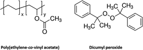
The molecular structures have been plotted in Fig. 1. Typical weight fraction of cross-linker in previous work is lower than 5% for bulky or film samples. In order to have a stronger network, the upper limit of 5% by weight of cross-linker is used in this study. However, the higher concentration of cross-linker renders more difficulty during the melting extrusion process. In addition, the length of the extruder limits the time of mixing. Furthermore, melt extrusion not only leads to mixing, but also causes chemical reaction. This is because chemical reaction occurs as long as the temperature is high enough to produce the free radicals. Once the chemical reaction is initiated, the viscosity of the mixture keeps growing. When the viscosity reaches a critical point, smooth fibrous morphology cannot be formed. To avoid this difficulty, a solid solution approach is used in this study.
The approach of preparing a PEVA–DP solid solution is illustrated in Fig. 2. At the beginning, both PEVA–tetrahydrofuran (THF) solution and DP–THF solution were prepared separately. Then an appropriate amount of DP–THF solution was added into the PEVA–THF solution. The new solution was blended into a uniform mixture by shaking at 70 °C. This mixture was then poured onto a large piece of Teflon sheet. Gelation occurred very quickly and prevented further motion of small molecules. After drying this gel by vacuum evaporation of the THF solvent, a well dispersed PEVA–DP solid solution was obtained. The solid solution was then granulated into small particles as raw materials for melt extrusion processing.
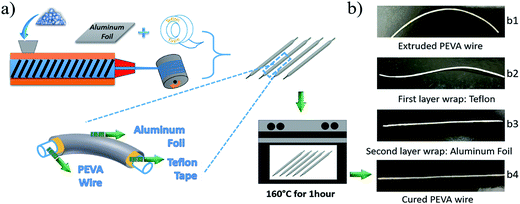
The second challenge is how to maintain the fibrous morphology during the curing process of the PEVA–DP solid solution. To deal with this challenge, we combine the curing process with the fiber manufacturing process. This is necessary because the extruded wire, which may have been partially cross-linked, is primarily a PEVA–DP solid solution and is very soft under the curing temperature of 150 °C. This suggests that the extruded wire will not be able to maintain its fibrous shape during curing. To address this problem, a so-called “double-layer wrap” approach is proposed as shown in Fig. 3(a).
In this process, the extruded wire was wrapped by Teflon tape which is easy to peel off as the inner layer. Then aluminium foil was wrapped onto it to maintain the shape during the curing as the outer layer. Digital photos of the wire wrapped by each step are presented in Fig. 3(b1)–(b3). The double-layer wrapped wires were placed in an oven for one hour under 160 °C for curing. After that, the oven was turned off, and the cured samples were gradually cooled down to room temperature. Finally, the two wrapping layers were peeled off and the 2W-SMP wires were obtained; see Fig. 3(b4).
The network formation process by chemical reactions in the curing process is illustrated in Fig. 4. The molar ratio of the vinyl acetate segments is around 1/13 in polymer chains calculated by the weight percentage of the vinyl acetate repeat unit. The high melting index of PEVA shortens the melting time, which is only several minutes. The decomposition of dicumyl peroxide into free radicals and the activation of polymer chains need much longer time. Although the melting of resins and the chemical reactions are coupled within the timeline, they are roughly divided into two steps here. Before chemical reactions, the continuous network of PEVA is maintained by chain entanglement and physical interaction between the chains. Due to the difference in polarity for the repeat units, similar segments will attract to each other. Because of the particular molar ratio of the repeat unit between ethylene and vinyl acetate, the crystallinity of PEVA is mainly contributed by “polyethylene-like” component. Besides, amorphous segments exist and connect the crystals together. When the material is heated up, the semi-crystalline polymer chains transform into amorphous chains gradually and form a pure amorphous state eventually. Simultaneously, the chemical reaction is initiated. Some segments of the polymer chains are activated into free radicals by disassociated peroxide radicals. The combination of two polymer free radicals creates a new “carbon–carbon” single bond. A new stable chemical network is achieved by this chemistry. The polymer chains will partially recrystallize into crystals when the material is cooled down. Different from the physically cross-linked network, the chemical cross-linked network can retain the structural functionality under a certain stress during the melting/crystallization process.
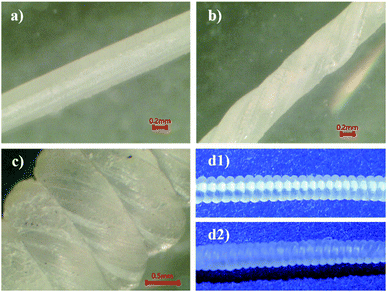
Subsequently, the cured wires were processed into artificial muscles by an established procedure. Firstly, the wires were stretched to 150% at 75 °C. The stretching transforms the thicker wire into a thinner fiber with a diameter about 0.45–0.5 mm. Then artificial muscles were fabricated through twist insertion by following our previous procedure.29,30 The fibers were twisted then coiled around a straight metal mandrel tightly as shown in Fig. 5(d1). The image was captured by a digital camera. The surface features of a stretched, twisted then coiled fiber were captured by an optical microscope as illustrated in Fig. 5(a)–(c), respectively. Thirdly, the twisted and coiled fibers were annealed. The heating was performed by a stepwise temperature ramp. The beginning equilibrium temperature was 55 °C. At each following step, the temperature was increased by 5 °C, and held for 30 min, until the temperature reached 80 °C. After that, the oven was turned off, and allowed naturally cooling down to room temperature, which completed the annealing process. Finally, the mandrel was removed and the artificial muscle was obtained. The digital photo of the annealed cPEVA artificial muscle without mandrel is shown in Fig. 5(d2).
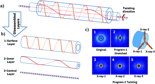
From the digital images captured by the microscope, a well-regulated and aligned feature is observed on the surface of the twisted fiber; see Fig. 5(b). The same feature also shows on the twisted then coiled fiber; see Fig. 5(c). To explore the orientation of crystallization in the material during processing, small angle X-ray scattering (SAXS) was performed for cPEVA fibers after each processing step as shown in Fig. 6(c). Coiling was caused by excessive twisting. Therefore, only twisted fiber was used as an example for the structural changes inside the fiber. The obtained SAXS measurement reveals several characteristics. First, an isotropic network was formed during the curing process; Fig. 6(c1). Second, the stretching operation aligned the lamellae of the crystals towards the direction of the external deformation, Fig. 6(c2), which is anticipated. However, thirdly, the crystals were re-oriented by twisting and the direction of the tilt did not simply follow the macroscopic surface orientation. Three measurements were performed on the same cross-section plane by different angles of incidence; Fig. 6(c3)–(c5). The observed scattered patterns are attributed to the anisotropic crystalline orientations to varying directions. This result can be understood by Fig. 6(a) and (b), i.e., each crystallite has different orientation after twisting, depending on its distance from the fiber central axis. Fourthly, the anisotropy of the crystalline is reduced after the twisting then coiling process, as compared to the fiber subjected to stretch only, Fig. 6(c2). Again, this is due to the fact that, under stretching only, the crystallites align along the same axial direction, suggesting higher anisotropy. After twisting, crystallites rotate along different directions, disrupting the almost uniaxial alignment, suggesting reduced anisotropy. For the crystallites at the fiber surface, they experienced the largest rotation, Fig. 6(b1); while the crystallites residing at the central axis of the fiber were hardly rotated, i.e., almost maintaining their alignment along the axial direction, Fig. 6(b3). As a result, the SAXS images took at different incidence angles show different scattering patterns.
Next, the actuation response and tunability of the fiber and muscle were investigated. In the following, the actuation strain is defined as follows:
| εact = (εH − εL) | (2) |
As shown in Fig. 7(a), we started by cycling the fiber in the temperature range of 20–67 °C under a constant tensile stress of 0.38 MPa. The actuation strain for each cycle is about 18%. After that, four cycles were conducted with temperature range from 20 °C to 59 °C, leading to an average actuation strain of 15%. After that, the fiber experienced four cycles of actuation, with a temperature range from 20 °C to 50 °C, which led to an average actuation strain of 9%. Lastly, the first temperature range was repeated, from 20 °C to 67 °C, for three cycles. We found that the average actuation strain was about 19%, which is very close to the previous cycles of 18%. The small difference can be attributed to small creep of the fiber. From the test results, it is clear that, as long as the high temperature and the low temperature, as well as the applied stress within a cycle are the same, the actuation behavior can be reasonably repeated, suggesting tunability, regardless of the actuation history.
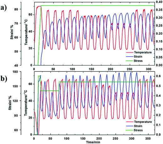 | ||
| Fig. 7 The tunable actuation behavior for (a) cPEVA fiber and (b) cPEVA artificial muscle in various temperature ranges and stress histories. | ||
In Fig. 7(b), the cPEVA muscle experienced a similar actuation history to the cPEVA fiber in Fig. 7(a). The only difference is that the muscle experienced varying external tensile load at the very beginning of the actuation process, in order to add more “history” to the muscle. After the initial varying stress period, the stress was maintained constant, 0.55 MPa. It is clear from Fig. 7(b) that, similar to the fiber, the muscle behavior is tunable. This is understandable because the 2W-SME for both the muscle and the fiber is driven by the melt/crystallization transition. Twist insertion in the fiber magnifies the tension actuation through untwisting. Table 1 summarizes the actuation responses of both the fiber and muscle.
| Sample | Temperature range designation | Temperature range [°C] | εH [%] | εL [%] | εact [%] | Ra | Pc [%] |
|---|---|---|---|---|---|---|---|
| a R is the ratio between εact (artificial muscle) to εact (fiber) in the same temperature range. | |||||||
| cPEVA fiber | 1 | 20–67 | 73 | 55 | 18 | 67.4 | |
| 2 | 20–59 | 75 | 60 | 15 | 43.5 | ||
| 3 | 20–50 | 76 | 67 | 9 | 23.9 | ||
| 4 | 20–67 | 75 | 56 | 19 | 67.4 | ||
| cPEVA artificial muscle | 1 | 20–67 | 172 | 104 | 68 | 3.8 | 67.4 |
| 2 | 20–59 | 174 | 111 | 63 | 4.2 | 43.5 | |
| 3 | 20–50 | 176 | 120 | 55 | 6.1 | 23.9 | |
| 4 | 20–67 | 172 | 105 | 67 | 3.5 | 67.4 | |
From Table 1, it is clear that (1) twist insertion has greatly increased the actuation strain. The ratio of the muscle actuation strain over the fiber actuation strain, i.e., R in Table 1, increases as the actuation temperature range narrows. Here, the ratio is 3.8 for the temperature range from 20–67 °C, which becomes 6.1 for the temperature range from 20 °C to 50 °C. Based on Yang et al.,51 the muscle actuation is due to both 2W-SME of the precursor fiber and untwisting of the muscle. With narrower actuation temperature range, the 2W-SME is reduced so that untwisting plays a decisive role, leading to higher actuation strain ratio; (2) the actuation temperature range (20–67 °C) is much lower than that of nylon 6,6 (20–160 °C),32 but doubles the actuation strain (68% for cPEVA but 34% for nylon 6,6). Obviously, the reduced actuation temperature and increased actuation strain make 2W-SMP an ideal candidate for some applications such as biomedical devices, soft robots, textiles, and toys; (3) the 2W-SME is due to the melt/crystallization transition. The percentage of the melted PEVA crystals decreases as the actuation temperature range narrows, leading to reduced actuation strain.
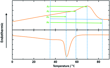
It is noted that the approximate percentage of the melted crystals in Table 1 for each actuation temperature range is calculated from the integration of the heat flow vs. temperature curve as shown in the DSC test results in Fig. 8. The integration of the interval A0 is the entire melting enthalpy for the cPEVA and the integrations of the intervals A1, A2 and A3 are the partial melting enthalpy for each corresponding actuation temperature range.
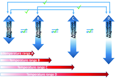
From the test results, we have seen that both the cPEVA fiber and muscle show tunable actuation. It is interesting to know the reason behind the tunability of the cPEVA muscle. Shape tunability is related to multi-shape memory effect (MSME). In a general sense, both one-way SMP (1W-SMP) and 2W-SMP can show MSME. This can be achieved by SMPs with broad glass transition52 or broad melting transition.45 Actually, MSME can also be found in 1W-SMPs with narrow glass transition by multi-direction programming.53 Fig. 9 illustrates the definition of tunability. It is seen that, tunability means that for each pair of shapes (one corresponds to high temperature and the other corresponds to low temperature within an actuation cycle), the pair of shapes can be repeated if the corresponding temperatures are repeated. As a result, the actuation strain, which is the difference between the strain at high temperature and the strain at low temperature, can also be reproduced, regardless of the actuation history. Based on this strict definition, fibers or muscles with creep are not tunable because the two shapes cannot be repeated, even though the actuation strain (the strain difference between the two shapes) can be reproduced. From Fig. 7, the cPEVA fiber, particularly the cPEVA muscle, is quite tunable in the strict meaning. This suggests that the chemical cross-links endow the 2W-SMP with a stable network, minimizing creep and ensuring reproduction of the shapes at both high temperature and low temperature. On the other hand, the melt/crystallization transition drives the shape shift between the low temperature and high temperature, ensuring reproduction of the actuation strain. The results in Fig. 7 suggests that, under a constant applied load, the melt/crystallization transition depends on the low temperature, the high temperature, and the difference between these two temperatures (actuation temperature), regardless of the history of actuation. The almost disappearance of the slight creep in the muscle, which is seen in the cPEVA fiber, is again an indication that muscle actuation depends on both 2W-SME of the precursor fiber, and the untwisting of the muscle. On the other hand, the actuation depends on 2W-SME only in the precursor fiber.
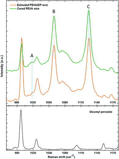
The Raman spectrum of the PEVA/DP wire, cured PEVA fiber and dicumyl peroxide are illustrated in Fig. 10. The peaks of the dicumyl peroxide are all relatively reduced (compared to the relatively unchanged peak such as peak B or peak C) after the crosslinking reaction, indicating that chemical reaction between PEVA and DP has occurred. Quantitative analysis of the peaks of PEVA is discussed as follow.
Raman spectroscopy is a quantitative characterization method regarding the concentration of the chemical bonds.56 The relative intensity of the peaks can be utilized to identify the variation of the amount of the chemical bonds. The peak A in the spectrum in Fig. 10 represents the C–C stretching vibration due to the methanetriyl group connecting to the methylene bridges. The peak B and peak C are both C–C stretching vibration corresponding to the molecular structure of –(CH2)n–.57 The intensity ratio of the peaks can be used for quantitative analysis of chemical bonds. The peak intensity ratio of peak B to peak C is constant before and after the reaction as given in Table 2. On the other hand, the peak intensity ratio of peak A to peak B is increased after the chemical reaction. This reveals that the amount of the methanetriyl group is increased after curing, as compared to the amount of the methanediyl group before curing, which is a reliable demonstration for the chemical crosslinking between the PEVA and DP.
| Peak A (1018 cm−1) | Peak B (1059 cm−1) | Peak C (1125 cm−1) | |||
|---|---|---|---|---|---|
| Mode | C–C stretching of >HC–CH2– | C–C asymmetric stretching due to all trans –(CH2)n– | C–C symmetric stretching due to all trans –(CH2)n– | ||
| Intensity of cured PEVA (a.u.) | 298.2 | 1194.7 | 1316.5 | 0.25 | 0.91 |
| Intensity of PEVA/DP mixture (a.u.) | 204.1 | 1125.5 | 1269.8 | 0.18 | 0.91 |
Conclusions
2W-SMP, as a thermally reversible material, demonstrated heating-induced contraction and cooling-induced expansion, similar to polymers with NCTEs. In this study, a chemically cross-linked 2W-SMP, cPEVA, can be processed into fibers by a solid solution and “double-layer wrap” approach. After twist insertion, the coiled fiber or muscle exhibits large actuation strain up to 68%, within a comparatively narrow actuation temperature range (20–67 °C). As compared with muscles made of fishing lines such as nylon 6,6, which is actuated from 20–160 °C with an actuation strain of 34%, the cPEVA muscles may find applications in areas such as biomedical devices, soft robots, textiles, toys, etc., where low actuation temperature and high actuation strain are mandated. It is proved that the muscle actuation is due to both melt/crystallization transition driven 2W-SME of the precursor fiber and untwist of the muscle. It is also found that twist insertion reduces the anisotropy of the fiber. The muscle performance is quite repeatable or tunable, as long as the low temperature and the high temperature within an actuation cycle are the same, regardless of the actuation history. As compared to the precursor fiber, the muscle tunability is even better because untwisting plays a significant role in muscle behavior, minimizing the negative impact of creep. It is believed that other 2W-SMPs such as chemically cross-linked poly(ε-caprolatone) (cPCL), which has actuation strain up to 70%, can achieve even larger stroke if it can be processed into fibers and then muscles.Acknowledgements
The authors gratefully acknowledge the financial support by National Science Foundation under grant number CMMI 1333997, Army Research Office under grant number W911NF-13-1-0145, and NASA cooperative agreement NNX16AQ93A under contract number NASA/LEQSF(2016-19)-Phase3-10. We also appreciate the help from Dr Lisa Bovenkamp-Langlois at CAMD for SAXS training and operation.References
- D. L. Brock, MIT AI Memo No. 1330, November 1991.
- R. Pelrine, J. Eckerle and S. Chiba, Proc. 3rd Int. Symp. Micro Machine and Human Science, Nagoya, Japan, October 1992 Search PubMed.
- R. Kornbluh, R. Pelrine, J. Eckerle and J. Joseph, Proc. of the 1998 IEEE International Conference on Robotics &Automation, Leuven, Belgium, May 1998, vol. 3 Search PubMed.
- R. Pelrine, R. D. Kornbluh, Q. Pei, S. Stanford, S. Oh, J. Eckerle, R. J. Full, M. A. Rosenthal and K. Meijier, Proc. of the SPIE, Smart Structures and Materials 2002: Electroactive Polymer Actuators and Devices (EAPAD), San Diego, California, July 2002 Search PubMed.
- J. D. W. Madden, N. A. Vandesteeg, P. A. Anquetil, P. G. A. Madden, A. Takshi, R. Z. Pytel, S. R. Lafontaine, P. A. Wieringa and I. W. Hunter, IEEE J. Oceanic Eng., 2004, 29, 706 CrossRef.
- R. H. Baughman, Science, 2005, 308, 63 CrossRef CAS PubMed.
- T. Mirfakhrai, J. D. W. Madden and R. H. Baughman, Mater. Today, 2007, 10, 30 CrossRef CAS.
- J. Foroughi, G. M. Spinks, G. G. Wallace, J. Oh, M. E. Kozlov, S. Fang, T. Mirfakhrai, J. D. W. Madden, M. K. Shin, S. J. Kim and R. H. Baughman, Science, 2011, 334, 494 CrossRef CAS PubMed.
- M. D. Lima, N. Li, M. J. Andrade, S. Fang, J. Oh, G. M. Spinks, M. E. Kozlov, C. S. Haines, D. Suh, J. Foroughi, S. J. Kim, Y. Chen, T. Ware, M. K. Shin, L. D. Machade, A. F. Fonseca, J. D. W. Madden, W. E. Voit, D. S. Galvão and R. H. Baughman, Science, 2012, 338, 928 CrossRef CAS PubMed.
- P. Chen, Y. Xu, S. He, X. Sun, W. Guo, Z. Zhang, L. Qiu, J. Li, D. Chen and H. Peng, Adv. Mater., 2015, 27, 1042 CrossRef CAS PubMed.
- C. M. Wayman, JOM, 1980, 32, 129 CrossRef CAS.
- R. H. Baughman, Synth. Met., 1996, 78, 339 CrossRef CAS.
- Q. M. Zhang, V. Bharti and X. Zhao, Science, 1998, 280, 2101 CrossRef CAS PubMed.
- M. Shahinpoor, Y. Bar-Cohen, J. O. Simpson and J. Smith, Smart Mater. Struct., 1998, 7, R15 CrossRef CAS.
- C. Chapman, A. Eshghinejad, M. Elahinia and J. Intell, J. Intell. Mater. Syst. Struct., 2011, 22, 1239 CrossRef CAS.
- S. M. Mirvakili, A. Pazukha, W. Sikkema, C. W. Sinclair, G. M. Spinks, R. H. Baughman and J. D. W. Madden, Adv. Funct. Mater., 2013, 23, 4311 CrossRef CAS.
- C. Ohm, M. Brehmer and R. Zentel, Adv. Mater., 2010, 22, 3366 CrossRef CAS PubMed.
- W. Guo, C. Liu, F. Zhao, X. Sun, Z. Yang, T. Chen, X. Chen, L. Qiu, X. Hu and H. Peng, Adv. Mater., 2012, 24, 5379 CrossRef CAS PubMed.
- Y. Shang, Y. Li, X. He, S. Du, L. Zhang, E. Shi, S. Wu, Z. Li, P. Li, J. Wei, K. Wang, H. Zhu, D. Wu and A. Cao, ACS Nano, 2013, 7, 1446 CrossRef CAS PubMed.
- C. Chou and B. Hannafor, IEEE Trans. Robot. Autom., 1996, 12, 90 CrossRef.
- B. Tondu, J. Intell. Mater. Syst. Struct., 2012, 23, 225 CrossRef CAS.
- M. Baghani, R. Naghdabadi and J. Arghavani, Smart Mater. Struct., 2012, 21, 045014 CrossRef.
- S. Sharafi and G. Li, Soft Matter, 2015, 11, 3833 RSC.
- D. Yue, X. Zhang, H. Yong, J. Zhou and Y. Zhou, Appl. Phys. Lett., 2015, 107, 111903 CrossRef.
- Q. Yang and G. Li, J. Mech. Phys. Solids, 2016, 92, 237 CrossRef CAS.
- T. Noritsugu and T. Tanaka, IEEE ASME Trans. Mechatron., 1997, 2, 259 CrossRef.
- W. Yim, J. Lee and K. J. Kim, Bioinspiration Biomimetics, 2007, 2, S31 CrossRef PubMed.
- M. A. McEvoy and N. Correll, Science, 2015, 347, 1328 CrossRef CAS PubMed.
- P. Zhang and G. Li, Polymer, 2015, 64, 29 CrossRef CAS.
- P. Zhang and G. Li, J. Compos. Mater., 2016, 50, 4235 CrossRef.
- M. C. Yip and G. Niemeyer, Proc. of 2015 IEEE international conference on robotics and automation (ICRA), Seattle, Washington, May 2015 Search PubMed.
- C. S. Haines, M. D. Lima, N. Li, G. M. Spinks, J. Foroughi, J. D. W. Madden, S. H. Kim, S. Fang, M. J. Andrade, F. Göktepe, Ö. Göktepe, S. M. Mirvakili, S. Naficy, X. Lepró, J. Oh, M. E. Kozlov, S. J. Kim, X. Xu, B. J. Swedlove, G. G. Wallace and R. H. Baughman, Science, 2014, 343, 868 CrossRef CAS PubMed.
- S. Aziz, S. Naficy, J. Foroughi, H. R. Brown and G. M. Spinks, Polym. Test., 2015, 46, 88 CrossRef CAS.
- A. Cherubini, G. Moretti, R. Vertechy and M. Fontana, AIP Adv., 2015, 5, 067158 CrossRef.
- G. Moretti, A. Cherubini, R. Vertechy and M. Fontana, SPEI Proc. Behavior and Mechanics of multifunctional materials and composites, San Diego, California, March 2015 Search PubMed.
- T. Chung, A. Romo-Uribe and P. T. Mather, Macromolecules, 2008, 41, 184 CrossRef CAS.
- J. Li, W. R. Rodgers and T. Xie, Polymer, 2011, 52, 5320 CrossRef CAS.
- M. Behl, K. Kratz, U. Noechel, T. Sauter and A. Lendlein, Proc. Natl. Acad. Sci. U. S. A., 2013, 110, 12555 CrossRef CAS PubMed.
- Y. Bai, X. Zhang, Q. Wang and T. Wang, J. Mater. Chem. A, 2014, 2, 4771 CAS.
- S. Pandini, D. Dioni, K. Paderni, M. Messori, M. Toselli, E. Bontempi and T. Riccò, J. Intell. Mater. Syst. Struct., 2016, 27, 1388 CrossRef.
- K. M. Lee, P. T. Knight, T. Chung and P. T. Mather, Macromolecules, 2008, 41, 4730 CrossRef CAS.
- S. J. Hong, W. Yu and J. H. Youk, Smart Mater. Struct., 2010, 19, 035022 CrossRef.
- M. Behl, K. Kratz, J. Zotzmann, U. Nöchel and A. Lendlein, Adv. Mater., 2013, 25, 4466 CrossRef CAS PubMed.
- L. Lu and G. Li, ACS Appl. Mater. Interfaces, 2016, 8, 14812 Search PubMed.
- T. Xie, J. Li and Q. Zhao, Macromolecules, 2014, 47, 1085 CrossRef CAS.
- S. Pandini, S. Passera, M. Messori, K. Paderni, M. Toselli, A. Gianoncelli, E. Bontempi and T. Riccò, Polymer, 2012, 53, 1915 CrossRef CAS.
- S. Pandini, F. Baldi, K. Paderni, M. Messori, M. Toselli, F. Pilati, A. Gianoncelli, M. Brisotto, E. Bontempi and T. Riccò, Polymer, 2013, 54, 4253 CrossRef CAS.
- J. Zhou, S. A. Turner, S. M. Brosnan, Q. Li, J. M. Y. Carrillo, D. Nykypanchuk, O. Gang, V. S. Ashby, A. V. Dobrynin and S. S. Sheiko, Macromolecules, 2014, 47, 1768 CrossRef CAS.
- Y. Meng, J. Jiang and M. Anthamatten, ACS Macro Lett., 2015, 4, 115 CrossRef CAS.
- J. Wang, J. Li, N. Li, X. Guo, Li. He, X. Cao, W. Zhang, R. He, Z. Qian, Y. Cao and Y. Chen, Chem. Mater., 2015, 27, 2439 CrossRef CAS.
- Q. Yang, J. Fan and G. Li, Appl. Phys. Lett., 2016, 109, 183701 CrossRef.
- T. Xie, Nature, 2010, 464, 267 CrossRef CAS PubMed.
- G. Li, A. King, T. Xu and X. Huang, J. Mater. Civ. Eng., 2013, 25, 393 CrossRef.
- X. L. Wu, W. M. Huang and H. X. Tan, J. Polym. Res., 2013, 20, 150 CrossRef.
- U. Nöchel, U. Kumar, K. Wang, K. Kratz, M. Behl and A. Lendlein, Macromol. Chem. Phys., 2014, 215, 2446 CrossRef.
- M. J. Pelletier, Appl. Spectrosc., 2003, 57, 20A CrossRef CAS PubMed.
- Y. Ren, M. Shimoyana, T. Ninomiya, K. Matsukawa, H. Inoue, I. Noda and Y. Ozaki, J. Phys. Chem. B, 1999, 103, 6475 CrossRef CAS.
| This journal is © The Royal Society of Chemistry 2017 |



![[thin space (1/6-em)]](https://www.rsc.org/images/entities/char_2009.gif) :
: