
 Open Access Article
 This Open Access Article is licensed under a
 Creative Commons Attribution 3.0 Unported Licence
Synthesis of a hierarchical structured NiO/NiS composite catalyst for reduction of 4-nitrophenol and organic dyes
Osman Ahmed Zelekew and
Dong-Hau Kuo*
and
Dong-Hau Kuo*
Department of Materials Science and Engineering, National Taiwan University of Science and Technology, No. 43, Sec. 4, Keelung Road, Taipei 10607, Taiwan. E-mail: dhkuo@mail.ntust.edu.tw; Fax: +886-2-27303291
First published on 16th January 2017
Abstract
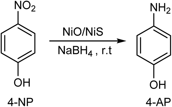
The NiO/NiS composite catalyst synthesis is designed using a simple and facile method. Composite materials with different sulfur sources were characterized and applied for catalytic reduction of 4-nitrophenol (4-NP) in aqueous solution. The catalysts' universality towards reduction/decolorization of other organic dyes such as methylene blue (MB), methyl orange (MO), and rhodamine B (RhB) was evaluated. The NiO/NiS (Ni-5) composite catalyst prepared with 10 mmol of Ni(Ac)2·4H2O and 5 mmol of thioacetamide had the best catalytic activity and the catalytic reduction of 4-nitrophenol (4-NP) to 4-aminophenol (4-AP) took only 6 min. The composite catalyst also performed very well for reduction of MB, MO, RhB, and a mixture of organic pollutants including 4-NP, MB, MO, and RhB, which were completed in 60, 30, 90, and 210 s, respectively. The results showed that the Ni-5 composite catalyst was highly active and efficient for complete reduction of organic pollutants at room temperature. The catalytic efficiency of the composite material originates from NiS as a catalyst and facilitates electron transfer together with the NiO hierarchical structure. The pollutants and the hydrogen adsorbed on the surface of the catalyst can be combined with each other so that reduction occurs easily. Therefore, the NiO/NiS composite material formed from low-cost nickel-based metal oxide and sulfide can be successfully applied towards the reduction of organic pollutants at room temperature.
1. Introduction
In the past few decades, the design and synthesis of heterojunction semiconductors, nanocrystal, and nanomaterial catalysts have attracted much attention because of their numerous technological applications in the scientific world.1–3 Among various semiconductor nanocrystals, nickel oxide (NiO) and nickel sulfide (NiS) have been mainly studied as potential candidates in different field areas.4,5 Particularly, NiO nanocrystals are an important and promising transition-metal oxide semiconductor because of their high chemical and thermal stability and being environmentally friend.6 Nowadays, an interest in NiO semiconductor material is growing because of its favorable physicochemical properties for a range of applications, such as photovoltaics, supercapacitor, batteries, photocatalysis, and absorbents.7–11 Similar to nickel oxide, nickel sulfide is also one of the widely studied semiconductor materials due to its excellent electrocatalytic activity.12 Due to this reason, extensive effort has been made to develop high efficient and cost-effective nickel based materials.To date, NiO semiconductor material has been used in different applications. Ci et al. used NiO-microflower as supercapacitor electrode.13 Zhu et al. synthesized ultrathin nickel hydroxide and oxide nanosheets for supercapacitor.14 Furthermore, Chen et al. and Shifu et al. reported the P–N junction NiO/TiO2 composite for photocatalyst application.15,16 On the other hand, Mandlimath et al. used first row transition metal oxides such as NiO, CuO, Co3O4, and other semiconductors for reduction of p-nitrophenol to p-aminophenol.17 Similarly, NiS semiconductor nanocrystals were also used for different applications. Wang et al. and Karthikeyan et al. applied NiS nanocrystal for dye-sensitized solar cells and nitrophenol reduction, respectively.12,18 However, the reports of using NiO and NiS semiconductor catalysts towards reduction of 4-NP and other different organic dyes are limited.
It is known that nitroaromatic compounds are extensively used in the manufacture of pigments, pharmaceuticals, dyes, explosives, plastics, and pesticides, and fungicidal agents.19 However, these organic compounds are highly hazardous contaminants, found in agricultural and industrial wastewaters which aggravate and have significant damages to the environment.20 Among nitroaromatic compounds, 4-nitrophenol (4-NP) is one of the most toxic and refractory organic pollutants frequently release from explosives, plasticizers herbicides, and pesticides industries.21 In addition to this, synthetic dyes in different industries such as leather treatment, dyeing of cloth, plastics, paper and pulp manufacturing, and printing have been used widely and could be a cause of environmental pollution.22,23 Particularly, dyes and pigments released from different industries with color into the aquatic ecosystems poses serious ecological problem and are also the major issue of water pollution in the world today.24–27 In addition to this, dyes such as MB, MO, and RhB are also high toxicity, carcinogenic, and mutagenic organic compounds. Due to this reason, extensive researches have been done for the removal of organic pollutants to reduce the risks.28 However, the decolorization of wastewaters is still one of worldwide difficulty to which many various technologies have been applied.29–32 Recently, technological applications such as adsorption, photocatalytic degradation, chemical oxidation, membrane filtration, flocculation, and reduction have been used to remove organic pollutants and decolonized wastewaters.33–38 Still now, the development of cost-effective, environmentally benign, and efficient techniques is an important concern in the field of environmentology.39,40
Recently, the reduction of organic pollutants has been carried out by metal nanoparticle (like, Ag and Au) based catalysts. However, the use of precious metal nanoparticle material makes the catalyst expensive. Moreover, the easy aggregation of metal nanoparticles limits their large scale applications, and sometimes needs the catalyst support.41–43 In order to avoid this problem, semiconductor materials could be used to treat organic pollutants containing wastewater.44 Among semiconductor materials, Ni-based oxide and sulfide attract particular attention due to their high chemical stability, nontoxic nature, and low cost.7,45 Furthermore, there is no report on NiO combined with NiS semiconductor for catalytic reduction applications of organic pollutants.
Based on the above considerations, we designed NiO and NiS composite catalysts with a facile method for catalytic reduction applications. It is suggested that the application of NiO towards catalytic activity is limited because of wider band gap of (3.4 eV). However, the combination of NiO and NiS semiconductors make the catalyst excellent and effective. It is suggested that NiS plays a significant role in transfer of electron.46 Our motivation here is a green synthesis of NiO/NiS composite catalysts, and its application for catalytic reductions of different kinds of organic pollutants at room temperature. We described the synthesis of NiO/NiS composite catalysts with different ratios of sulfur source in aqueous solution. The NiS nanoparticles are formed through simple anion-exchange after addition of sulfur sources into nickel salt and urea suspensions. This synthesis approach of the composite catalysts is important to avoid separation and re-dispersion step processes. It is also used for managing over aggregation and particle size growth.
2. Experimental methods
2.1 Chemicals
The chemicals used in this work were analytical grade and used without further purifications. DI water was used throughout the experiment.2.2 Synthesis of NiO/NiS composite catalysts
The synthesis of NiO/NiS composite catalysts was carried out as follows. Typically, 10 mmol of Ni(Ac)2·4H2O and 5 g of urea were readily dissolved into 400 mL of water. Then, 5 mmol of thioacetamide dissolved with 100 mL of water was dropped to the Ni precursor solution. The mixture was heated at 90 °C for 4 h under stirring. After cooling at room temperature, the solution was centrifuged and washed with water and ethanol. Then, the precipitate was dried and annealed at 450 °C for 3 h. The resulting powder was obtained and abbreviated as NiO/NiS (Ni-5). Furthermore, to investigate the catalytic activity of the composite materials, different molar ratios of sulfur sources (0, 2.5, 10, and 15 mmol) of thioacetamide were used with 10 mmol Ni(Ac)2·4H2O sources for each composite. The composite powders formed with thioacetamide ratios of 0, 2.5, 10, and 15 mmol together with 10 mmol of Ni(Ac)2·4H2O were abbreviated as Ni-0, Ni-2.5, Ni-10, and Ni-15, respectively. The abbreviations are used throughout the manuscript. Scheme 1 shows schematic procedure for typical Ni-5 composite catalyst. | ||
| Scheme 1 Schematic synthetic procedure for NiO/NiS (Ni-5) composite catalyst. | ||
2.3 Characterizations
The crystal structures of the as-prepared and annealed composite materials were characterized by X-ray diffraction (XRD) using Cu Kα radiation (λ = 1.5418 Å) source. The morphologies of the composite materials were observed by field-emission scanning electron microscopy (FE-SEM, JSM 6500F, JEOL, Tokyo, Japan). The ultraviolet-visible diffuse reflectance spectrum and catalytic performance of the catalysts were evaluated by JASCO V-670 UV-visible-near-infrared spectrophotometer.2.4 Catalytic activity test
Catalytic reduction of 4-NP to 4-AP was carried out at room temperature according to the following procedure. Briefly, 100 mL of 4-NP (20 ppm) aqueous solution and 5 mL of freshly prepared NaBH4 (0.1 M) were mixed into a beaker. Then, 10 mg of catalyst was added to the reaction mixture. After that, the reduction progress of 4-NP was checked at different intervals of time by a JASCO V-670 UV-visible spectrophotometer.To check the wide applications of the composite catalyst towards reduction of other organic dyes, the performance was evaluated by reduction/decolorization of MB, MO, and RhB dyes. With the same approach of 4-NP reduction, 100 mL of aqueous solution MB (20 ppm) dye and 5 mL of NaBH4 (0.1 M) were mixed together in the beaker. Then, 10 mg of catalyst sample was added into the above solution at room temperature and the absorption peak was recorded. The reduction of RhB and MO dyes was also monitored with similar procedure of MB dye reduction. Furthermore, the reduction of organic pollutant mixtures with 4-NP, MB, MO, and RhB all together was also performed by taking 25 mL of the 20 ppm solutions from each pollutant. The amount of NaBH4 and the catalyst loaded were similar to the reduction of 4-NP. The recycling experiment was performed after separation of the catalysts by centrifugation. The used catalyst was washed with DI water, dried, and reused for the next run.
3. Results and discussion
3.1 Characterization
X-ray diffraction (XRD) patterns of the prepared NiO and NiO/NiS composite are shown in Fig. 1. The major diffraction peaks of NiO at about 37.2° for (111), 43.2° for (200), and 62.8° for (220) planes are observed in all composite catalysts (Fig. 1a–e). The obtained diffraction peaks are in agreement with the standard pattern peaks of cubic NiO structure (JCPDS No. 04-0835). Moreover, the major peaks of NiS phase were also observed at 30.2° for (100), 34.7° for (101), 45.8° for (102), and 53.7° for (110) planes (Fig. 1c–e). The peaks from the NiS structure agreed with the standard pattern peaks of α-NiS hexagonal phase (P63/mmc) (JCPDS No. 02-1280). However, the NiS peaks at Fig. 1b are not clearly observed because NiS nanoparticles are smaller and the peak intensities are weak due to lower amount of sulfur source. Furthermore, additional smaller peaks shown at 22.6° for (020), 26.6° for (021), and 24.9° for (111) planes belonged to NiSO4 (JCPDS No. 76-0220). The structures of NiO and NiS are crystallized well. Without sulfur source, the NiO peaks can be clearly seen (Fig. 1a). Moreover, in the presence of smaller amount of sulfur source, the dominant structural peaks were broadened and remained as NiO (Fig. 1b). As the sulfur source increased, the peaks for NiS appeared in Fig. 1c–e for Ni-5, Ni-10, and Ni-15 composite catalysts. | ||
| Fig. 1 XRD patterns of (a) Ni-0, (b) Ni-2.5, (c) Ni-5, (d) Ni-10, and (e) Ni-15 composite catalysts. | ||
The formation mechanism of flower-like morphology comes from NiO which is formed after calcinations of Ni(OH)2. In the synthetic process, structure of Ni(OH)2 involves because of the formation of nanoparticles and growth into nanosheets, followed by self-assembly into flower-like structure.47 On the other hand, the nanosheets can assemble into flower-like architecture because of the crystal face attraction, van der Waals forces, electrostatic and dipolar fields associated with the aggregate, and hydrogen bonds.48 Moreover, the decomposition of urea also used as a soft template to encourage self-assembly of the nanosheets. Self-assembly and Ostwald ripening process also occur in the gas and liquid interfaces of CO2 and water, leading to the formation of flower-like hierarchical structure of Ni(OH)2.47,49 As it is shown from eqn (1)–(4), the chemical reactions in the syntheses of NiO and NiS composite catalysts were based on hydrolysis of urea. The hydrolysis of urea could generate OH− and CO32− which then reacted with Ni2+ to form nickel carbonates and hydroxides.13 Moreover, the formation of NiS involves with anion-exchange reaction between OH− and CO32−, and S2− ions because of the solubility product differences. In general, materials with higher solubility product constant (Ksp) values are thermodynamically less stable than those with lower Ksp. Hence, NiS is likely formed by simple anion-exchange reactions because the Ksp value of NiS (Ksp = 1 × 10⁻²²) is lower than NiCO3 (Ksp = 1 × 10⁻⁷) and Ni(OH)2 (Ksp = 2 × 10⁻¹⁶).50,51 Since limited amount of sulfur sources is available in the solution, not all hydroxides are replaced by sulfur ion. Finally, calcinations of the flower-like Ni(OH)2 transforms into NiO with morphology maintained and the removal of interlayer anion.47,49 The major reactions involved during synthesis of the composite catalysts are illustrated as follows in eqn (1)–(4).
| 2NH2(CO)NH2 + 5H2O → 4NH4+ + 2OH− + CO32− + CO2 | (1) |
| 2Ni2+ + 2OH− + CO32− → NiCO3·Ni(OH)2 | (2) |
| NiCO3·Ni(OH)2 + 2S2− → 2NiS + 2OH− + CO32− | (3) |
| NiCO3·Ni(OH)2 → 2NiO + CO2 + H2O | (4) |
Morphologies of the synthesized NiO/NiS heterostructure composites investigated by using the FE-SEM are shown in Fig. 2. Fig. 2a–d show the FE-SEM images of the as-prepared Ni-2.5, Ni-5, Ni-10, and Ni-15 composites, respectively. The morphology of Ni-2.5 revealed that the NiO phase shows hierarchical structures, as the amount of sulfur source was low (Fig. 2a). For this reason, only small amount of NiS nanoparticles are formed together with hierarchical structures of NiO. On the other hand, as we increased the source of sulfur to 5 mmol (Ni-5), the morphology had some changes (Fig. 2b), where the NiS nanoparticles were formed together with NiO structures. With further increases in the sulfur sources to 10 and 15 mmol, the morphologies changed from hierarchical flower-like structure to nanoparticles (Fig. 2c and d). It reveals that the NiS nanoparticles are formed predominantly and the NiO hierarchical structures are covered by the resulting NiS particles. Generally, the NiO hierarchical structures are formed predominantly in the presence of lower sulfur source, while the addition of more sulfur sources results in mainly the NiS nanoparticles.
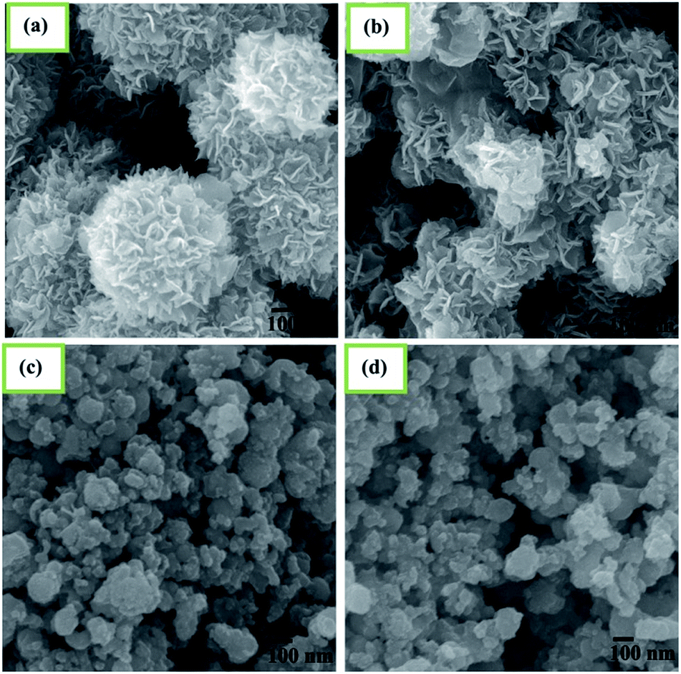 | ||
| Fig. 2 SEM images of (a) Ni-2.5, (b) Ni-5, (c) Ni-10, and (d) Ni-15 composite catalysts. | ||
Absorption spectra of Ni-0, Ni-2.5, Ni-5, Ni-10, and Ni-15 composite catalysts are illustrated in Fig. 3. The absorption spectrum of Ni-0 was observed in the UV range at about 300–370 nm. This absorption range indicated that there was the formation of NiO with estimated band gap of 3.42 eV. With the addition of 2.5 mmol of sulfur source (Ni-2.5), the absorption of composite material is observed in UV light range and has continuously extended to the visible light range. Moreover, the absorption of Ni-2.5 under visible light is higher than that of Ni-0. This absorption under visible region is due to the presence of lower band gap NiS nanoparticles in the composite catalyst. For the composite catalysts of Ni-5, Ni-10, and N-15, they all had continuous absorption spectra in both UV and the visible regions. With the higher sulfur source, Ni-15 composite catalyst with more NiS nanoparticles has the higher absorption under the visible light than Ni-10 and Ni-5. Hence, the considerable changes on visible-light absorption of the composite materials are contributed from NiS nanoparticles.
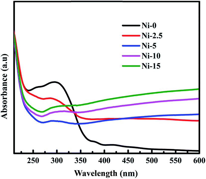 | ||
| Fig. 3 Absorption spectra for Ni-0, Ni-2.5, Ni-5, Ni-10, and Ni-15 composite catalysts. | ||
3.2 Catalytic activity
The catalytic performance of the prepared NiO and other different NiO/NiS composite catalysts was investigated with the reduction of 4-NP to 4-AP as a model reaction in the presence of NaBH4. It is familiar that the 4-NP aqueous solution shows the maximum absorption peak at 317 nm.19 However, the absorption peak of 4-NP shifted to 400 nm is ascribed to the formation of 4-nitrophenolate ion due to an increase in alkalinity upon addition of aqueous NaBH4 (Fig. 4a).52–54 Although the reduction of 4-NP with NaBH4 is thermodynamically feasible (Eo for 4-NP/4-AP = −0.76 V and H3BO3/BH4− = −1.33 V versus NHE), the reduction reaction rate is extremely slower due to the presence of kinetic barrier.55,56 Hence, the reduction did not proceed without addition of catalyst with the peak at 400 nm unchanged over 28 min after addition of NaBH4 aqueous solution (Fig. 4b).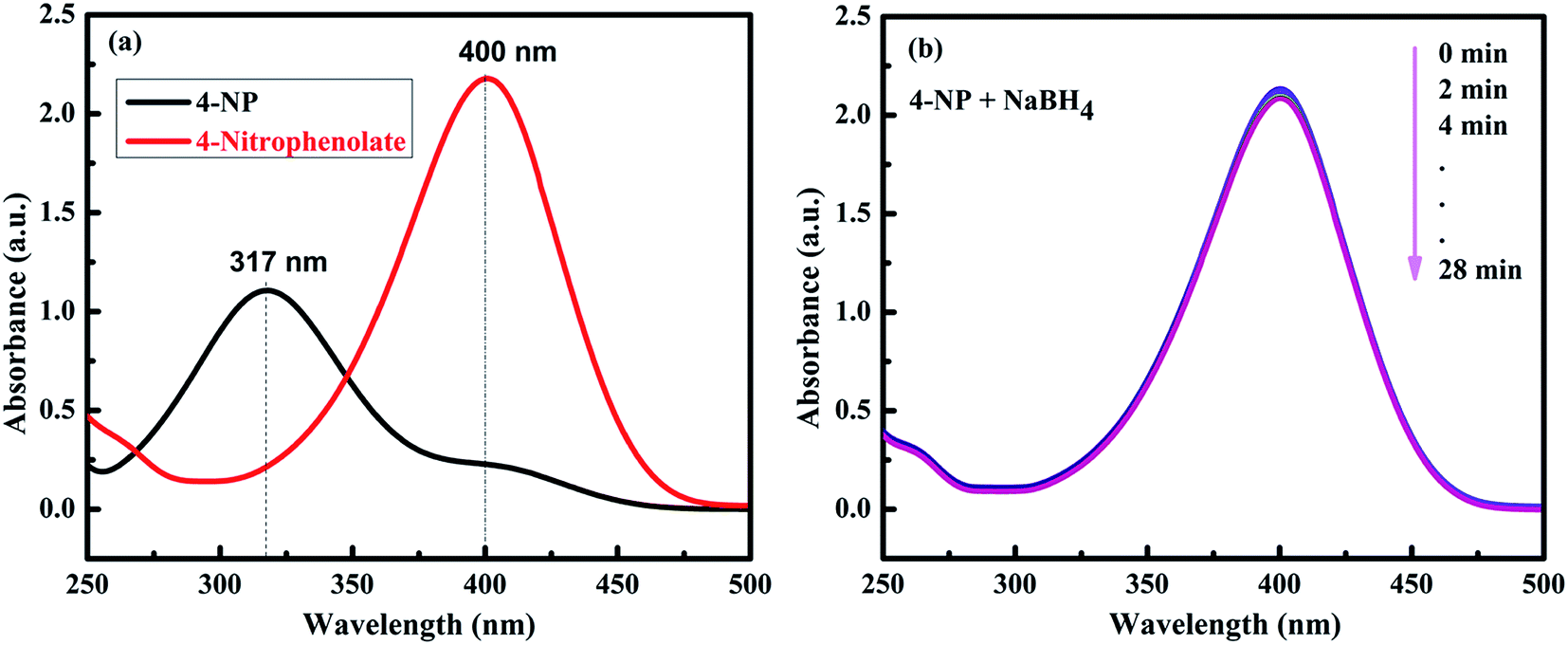 | ||
| Fig. 4 (a) UV-vis spectra of 4-NP before and after the addition of NaBH4 solution. (b) The time-dependent successive reduction of 4-NP with NaBH4 only without catalyst. | ||
The catalytic activities of the Ni-0, Ni-2.5, Ni-5, Ni-10, and Ni-15 composite catalysts were investigated in the reduction reaction of 4-NP (Fig. 5). After addition of the catalysts, the intensity of the absorption peak at 400 nm gradually decreased as the reduction reaction proceeded. Simultaneously, a new absorption peak appeared at 300 nm and the yellow color of 4-nitrophenolate ion changed into colorless solution which indicates the reduction of 4-NP to 4-AP.57,58 The catalytic performance of each composite catalyst was monitored by UV-vis spectrometry at interval of time. Fig. 5a–e shows the absorption spectra after successive reduction reactions for 4-NP with Ni-0, Ni-2.5, Ni-5, Ni-10, and Ni-15 composite catalyst, respectively. In the presence of Ni-0 catalyst, the reduction of 4-NP into the corresponding 4-AP took 20 min for 55% conversion (Fig. 5a). However, it took less than 16 min for Ni-2.5 (Fig. 5b). The results indicated that, Ni-2.5 composite catalyst had better reduction capability than Ni-0. On the other hand, the Ni-5 (Fig. 5c) and Ni-10 (Fig. 5d) catalysts needed only 6 min and 11 min, respectively, to complete the reduction of 4-NP. For Ni-15, 91% of 4-NP was converted into the corresponding 4-AP within 20 min (Fig. 5e). Hence, the composite catalysts with the best performance need to have the optimal sulfur source during preparation.
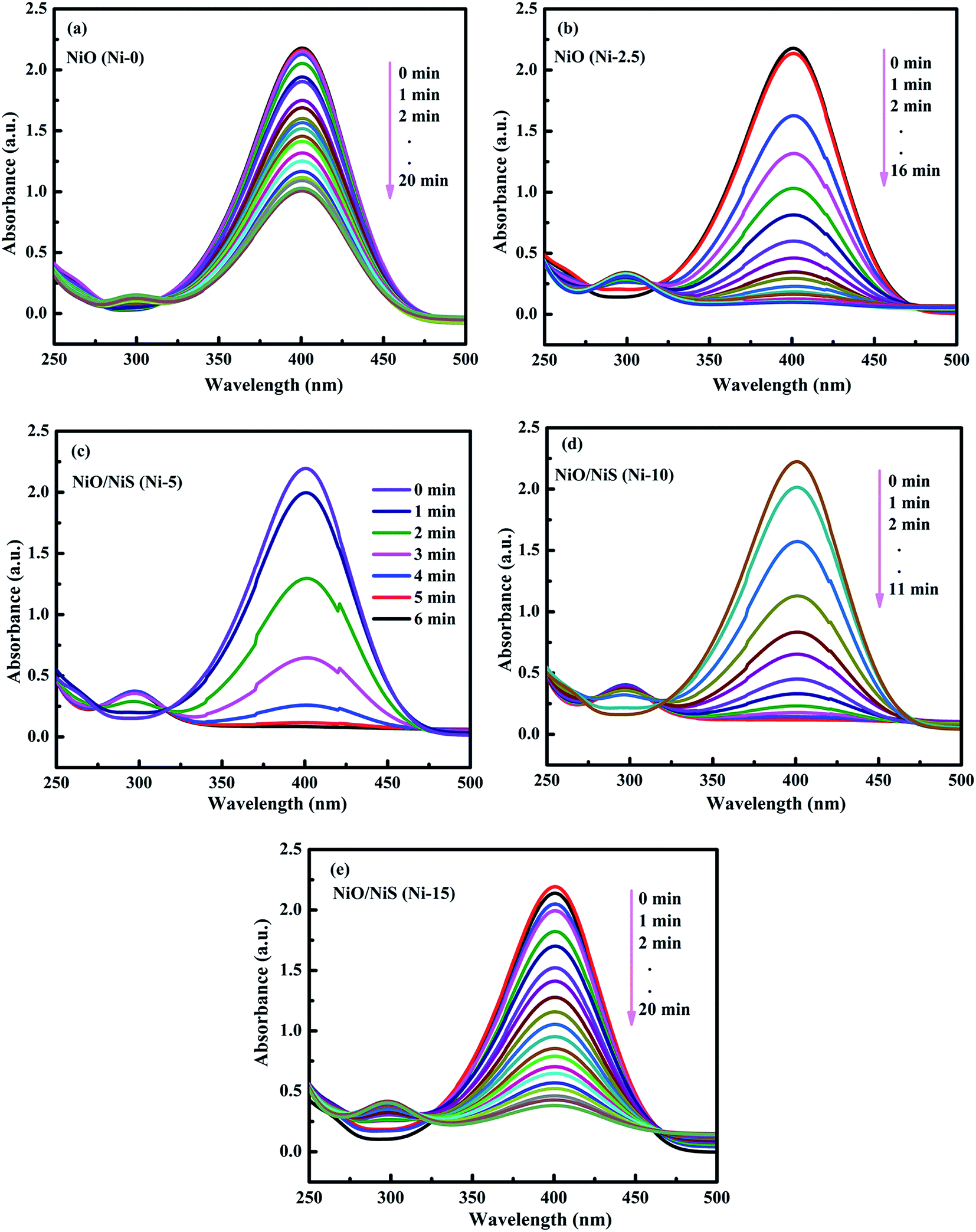 | ||
| Fig. 5 The time-dependent successive reduction of 4-NP into 4-AP over (a) Ni-0, (b) Ni 2.5, (c) Ni-5, (d) Ni-10, and (e) Ni-15 composite catalysts. | ||
Fig. 6a shows the plots of Ct/C0 concentration ratio as a function of reaction time (t), where C0 and Ct correspond to the initial absorbance and the absorbance at time (t) for peaks located at 400 nm, respectively. As it is observed from Fig. 6a, the reduction of 4-NP was faster in the presence of Ni-5 composite catalyst. Hence, the optimal amount of sulfur sources among others in the composite was 5 mmol thioacetamide together with 10 mmol of Ni(Ac)2·4H2O precursor. Furthermore, Ni-0 (NiO) only can reduce 4-NP about 55% within 20 min, indicating that NiO particles can also accept and transfer electron and facilitate for reduction of nitroarene compounds.59 However, its reduction reaction is still slow because of its higher band gap energy. As we add the sulfur source to form NiO/NiS composites, the reduction capability has been much improved. Our experimental data demonstrate that NiS with the low band gap energy can improve catalytic ability by accepting and transferring electrons from NaBH4 towards 4-NP. In other words, NiS acts as a co-catalyst to provide the active sites for the generation of hydrogen atom. The resulting hydrogen will contact with the electronegative active site of the pollutants and reduce them into the corresponding products.
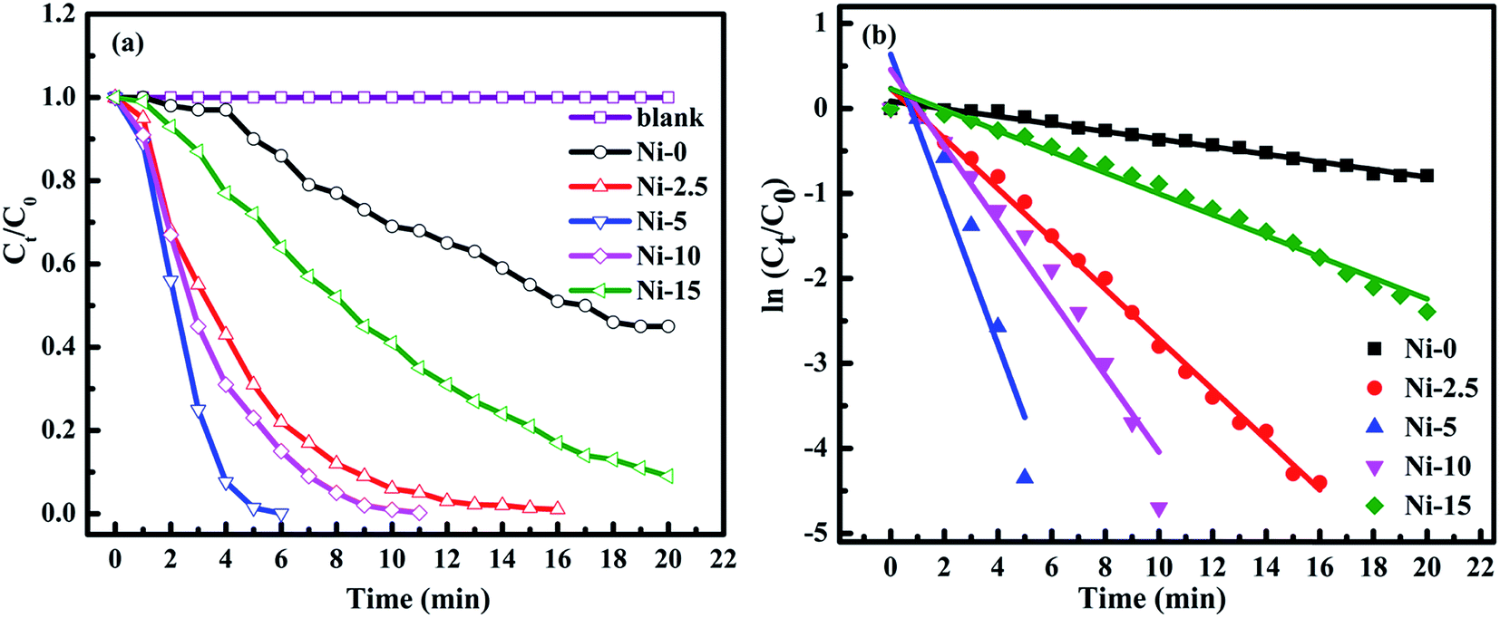 | ||
| Fig. 6 (a) Plots of Ct/C0 versus reaction time (min) for reduction of 4-NP without catalyst and with Ni-0, Ni-2.5, Ni-5, Ni-10, and Ni-15 catalysts. (b) Plots of ln(Ct/C0) versus reaction time (min) for reduction of 4-NP with Ni-0, Ni-2.5, Ni-5, Ni-10, and Ni-15 catalysts. | ||
The reactions (5) and (6) show the electron (e) transfer and electrochemical desorption capabilities of NiS. The formation of the hydride ion on the surface of NiS catalysts has been reported in literature.46 Reaction (7) also shows the catalytic reduction of 4-NP to 4-AP in the presence of NiO/NiS composite catalyst at room temperature (r.t).
| NiS + e + H+ → HNiS | (5) |
| HNiS + e + H+ → NiS + H2 | (6) |
 | (7) |
Moreover, the pseudo-first-order kinetics is also applied with respect to 4-NP concentration because NaBH4 is excess in the reaction mixture and its concentration can be considered as constant throughout the reaction.57 During the reduction of 4-NP, after the addition of NaBH4, there is always a short induction period. This induction period is corresponding to the time required for catalyst activation and common to heterogeneous catalysts. The induction period is also probably related to the initial adsorption of 4-NP at the active sites of the catalyst before the reduction reaction could start. The 4-NP reduction to 4-AP is monitored and then an apparent rate constant (kapp) can be derived from the slope of the ln(Ct/C0) versus t (min) plot.60–62 Fig. 6b illustrates the plot of ln(Ct/C0) versus t (min). The linear fit applied between ln(Ct/C0) and reaction time (t) is assumed to be pseudo-first-order reaction kinetics.63 The apparent rate constants (kapp) calculated from the slopes were 0.045, 0.295, 0.854, 0.450, and 0.124 min−1 for Ni-0, Ni-2.5, Ni-5, Ni-10, and Ni-15 composite catalysts, respectively.
The comparison of the catalytic activity of NiO/NiS (Ni-5) composite catalyst with the related reported metal oxides and Ni-based catalysts used for the reduction of 4-NP is illustrated in Table 1. According to the literature report, Co3O4 catalysts have the activity parameter of about 0.13 s−1 g−1.17 The NiPt-0.6% and RGO/PtNi (25![[thin space (1/6-em)]](https://www.rsc.org/images/entities/char_2009.gif) :75) catalysts show the activity parameters of about 1.2 and 0.37 s−1 g−1, respectively.64,65 Furthermore, the Ni/SiO2@Au MHMs activity parameter is about the 2.5 s−1 g−1.66 However, the NiO/NiS (Ni-5) composite catalyst has the ratio activity parameter constant of about 1.4 s−1 g−1, which is comparable with reported literature values.
:75) catalysts show the activity parameters of about 1.2 and 0.37 s−1 g−1, respectively.64,65 Furthermore, the Ni/SiO2@Au MHMs activity parameter is about the 2.5 s−1 g−1.66 However, the NiO/NiS (Ni-5) composite catalyst has the ratio activity parameter constant of about 1.4 s−1 g−1, which is comparable with reported literature values.
| No. | Catalysts/amount | Time (s) | Kinetic rate constant, kapp (s−1) | Ratio constant, K (s−1 g−1) | Ref. |
|---|---|---|---|---|---|
| 1 | Co3O4/0.1 g | 120 | 0.013 | 0.13 | 17 |
| 2 | NiO/0.1 g | 1080 | — | — | 17 |
| 3 | NiPt-0.6%/15.5 mg | 140 | 0.01882 | 1.2 | 64 |
| 4 | RGO/PtNi (25:75)/3 mg |
1800 | 0.00112 | 0.37 | 65 |
| 5 | Ni/SiO2@Au MHMs/4 mg | 300 | 0.01 | 2.5 | 66 |
| 6 | NiO/NiS (Ni-5)/10 mg | 360 | 0.014 | 1.4 | This work |
To check the wide applications and catalytic efficiencies of Ni-5 composite catalyst, the reduction reactions of different dyes such as MB, MO, and RhB were tested together with NaBH4. The catalytic reduction reactions were checked by UV-vis spectrophotometer. It is known that organic dyes such as MB, MO, and RhB are released from industries and are the organic environmental pollutants. Hence, the development of reliable and efficient methods for catalytic reduction of these organic pollutants is an important task.22,28,67 The decreases in intensity of the absorbance at λmax of 664 nm for MB, 464 nm for MO, and 554 nm for RhB were determined with interval of time (Fig. 7a–c). The decrease in intensities of the maximum absorbance with reaction time indicates that Ni-5 is able to reduce MB, MO, and RhB dyes. Furthermore, the catalytic efficiency of Ni-5 was also tested with the mixture of organic pollutants including 4-NP, MB, MO, and RhB. The decolorization/reduction of mixed organic pollutant solution was completed within 7 min (Fig. 7d). Hence, our composite catalyst is effective for all individual pollutants as well as for their mixed pollutants.
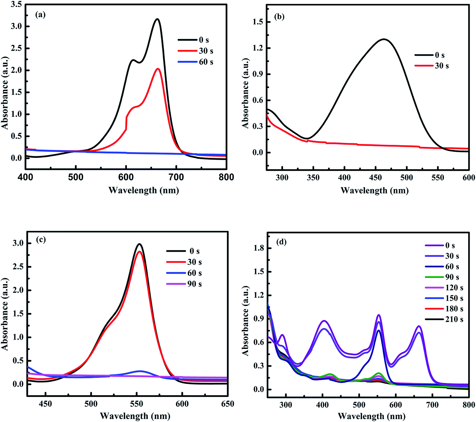 | ||
| Fig. 7 The time-dependent successive reductions of (a) MB, (b) MO, (c) RhB, and (d) the mixed 4-NP, MB, MO, and RhB pollutant solution. | ||
The catalytic reduction reactions for MB, MO, and RhB dyes were carried out at room temperature. The complete reduction of MB by NaBH4 is illustrated by the disappearance of blue color (MB) to colorless leuco-methylene blue (LMB). In similar manner, the reduction of MO dye is demonstrated by the disappearance of orange color to colorless products. The reduction of RhB also shows the disappearance of violet color to colorless leuco-rhodamine B (LRhB).38,67,68
Furthermore, the mechanism for reduction of 4-NP over NiO/NiS is also illustrated and a possible mechanism for the reduction of 4-NP is shown in Fig. 8. Initially, the hydride ion released from NaBH4 in aqueous solution is attached on the surface of the catalyst (step 1). In step 2, the hydrogen is covalently bonded to NiO or NiS. Then, the adsorption of nitro groups of 4-NP, which is the rate-determining step, takes place on the surface of the catalyst (step 3). After that, strong interactions between adsorbed 4-NP and bonded hydrogen atoms occur. The adsorbed nitro groups are attacked by the hydride ion and reduction occurs through the relay of electron from donor BH4− to the acceptor 4-NP, leading to the desorption of 4-AP product.69 For other organic dye, the mechanism is also similar to 4-NP reduction. Fig. 8 shows the mechanism of 4-NP reduction catalyzed by NiO/NiS.
 | ||
| Fig. 8 The mechanism of 4-NP reduction with NiO/NiS catalyst. | ||
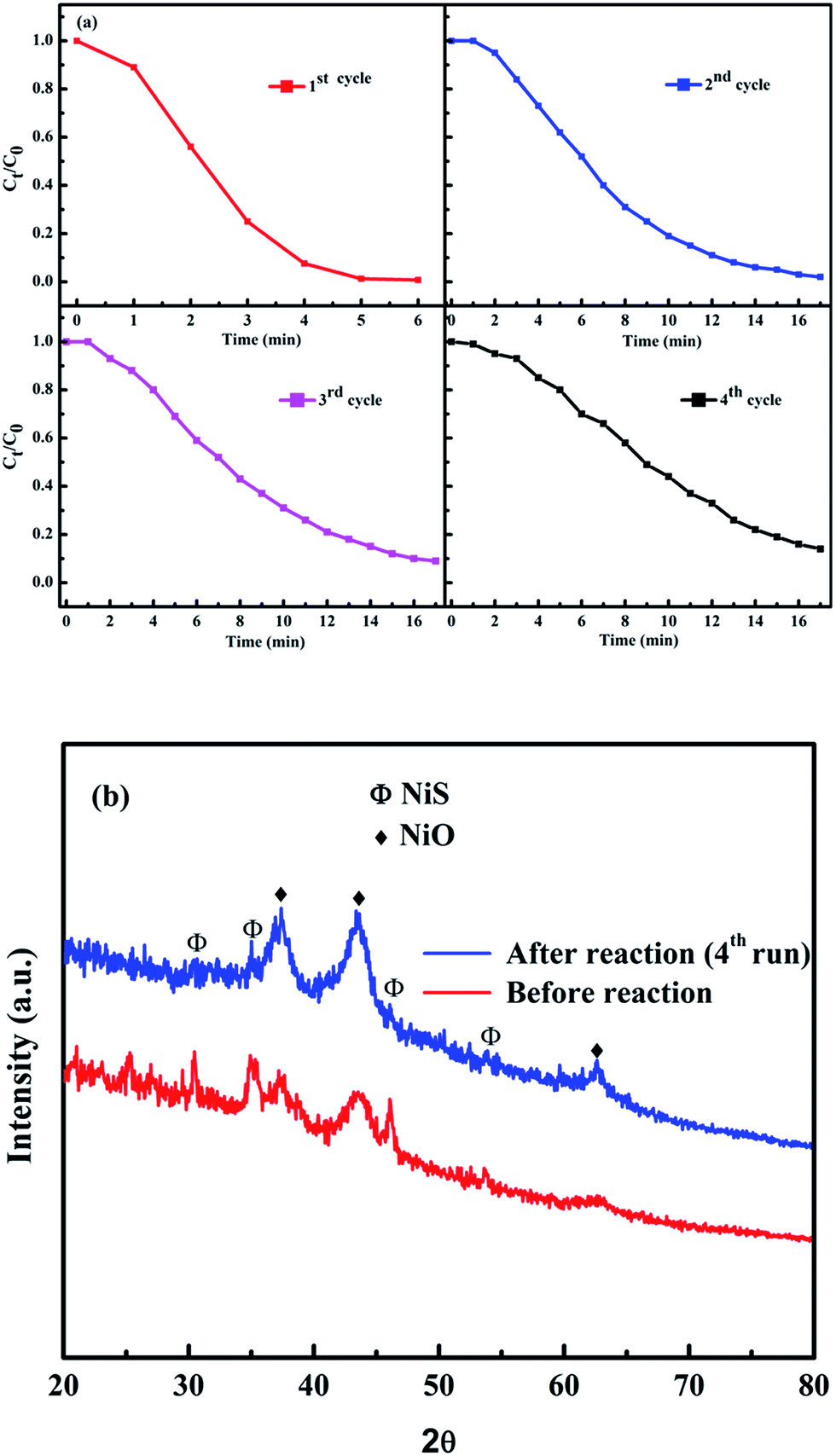
The reusability of our catalyst was tested for reduction of 4-NP to 4-AP. Fig. 9 shows the reusability of Ni-5 composite catalyst towards catalytic reduction of 4-NP. The used catalyst was collected and washed to test the reusability for next cycle. The performance of the catalyst was stable after the 2nd run and worked effectively. However, 2nd, 3rd, and 4th cycles were not as fast as the first run. For the 2nd, 3rd, and 4th cycles, about 95%, 91%, and 86% of the reduction of 4-NP to 4-AP were converted in 17 min, respectively. As we have seen from the reusability data, the re-used catalyst is not as good as the first cycle. Although the catalytic activity of reused composite catalyst decreases as compared with the 1st run, it is still working and the catalytic activity of the composite after the fourth run was still higher than that of pure NiO (Ni-0). After four runs of the reaction, we checked the XRD pattern of the powder and compared with original one (Ni-5). As we have seen from Fig. 9b, the NiS peak intensities after four runs decreased. This may be due to the reaction of NaBH4 with NiS in the solution. Hence, further study is needed to make performance of the composite catalyst as good as its first run.
 | ||
| Fig. 9 (a) Reusability and (b) XRD patterns before and after reactions for fourth cycles of Ni-5 composite catalysts towards reduction of 4-NP. | ||
4. Conclusions
Highly active and efficient NiO/NiS composite catalysts with different sulfur contents have been successfully prepared via a facile route. The characterizations of the as-prepared and annealed composite catalysts were performed with different techniques. The catalytic efficiency was tested on the reduction of different organic pollutants such as 4-NP, MB, MO, and RhB at room temperature. The apparent rate constants (kapp) for the conversion of 4-NP to 4-AP were 0.045, 0.295, 0.854, 0.450, and 0.124 min−1 for Ni-0, Ni-2.5, Ni-5, Ni-10, and Ni-15 composite catalysts, respectively. The Ni-5 prepared from 10 mmol of Ni(Ac)2·4H2O and 5 mmol of thioacetamide had the best catalytic performance for 4-NP. The catalytic reductions of Ni-5 on MB, MO and, RhB were also effective. The complete conversion of MB, MO and, RhB took 60, 30, and 90 s, respectively. Hence, the band alignment of high band gap NiO material with excellent light-harvesting NiS is an important aspect to make the catalyst efficient and active due to the feasible ability in electron transfer. NiO/NiS composite catalyst can be used to make the reduction reaction faster and can help the reduction/decolorization of organic pollutants in water to make the environment better.Acknowledgements
This work was supported by Ministry of Science and Technology of the Republic of China under Grant MOST 104-2221-E-011-169-MY3 and by the National Taiwan University of Science and Technology through Grant 105H451714.References
- S. Liu, J. Ke, H. Sun, J. Liu, M. O. Tade and S. Wang, Appl. Catal., B, 2017, 204, 358–364 CrossRef CAS.
- J. Park, J. Joo, S. G. Kwon, Y. Jang and T. Hyeon, Angew. Chem., Int. Ed. Engl., 2007, 46, 4630–4660 CrossRef CAS PubMed.
- X. Li, J. Liu, A. F. Masters, V. K. Pareek and T. Maschmeyer, APL Mater., 2013, 1, 041101 CrossRef.
- D. Liu, D. Li and D. Yang, Cryst. Res. Technol., 2016, 51, 313–317 CrossRef CAS.
- L. Tian, L. Y. Yep, T. T. Ong, J. Yi, J. Ding and J. J. Vittal, Cryst. Growth Des., 2009, 9, 352–357 CAS.
- S. Zhang, J. Li, T. Wen, J. Xu and X. Wang, RSC Adv., 2013, 3, 2754–2764 RSC.
- J. H. Pan, Q. Huang, Z. Y. Koh, D. Neo, X. Z. Wang and Q. Wang, ACS Appl. Mater. Interfaces, 2013, 5, 6292–6299 CAS.
- U. M. Patil, R. R. Salunkhe, K. V. Gurav and C. D. Lokhande, Appl. Surf. Sci., 2008, 255, 2603–2607 CrossRef CAS.
- J. Ma, J. Yang, L. Jiao, Y. Mao, T. Wang, X. Duan, J. Lian and W. Zheng, CrystEngComm, 2012, 14, 453–459 RSC.
- C. Luo, D. Li, W. Wu, C. Yu, W. Li and C. Pan, Appl. Catal., B, 2015, 166–167, 217–223 CrossRef CAS.
- X. Rong, F. Qiu, J. Qin, H. Zhao, J. Yan and D. Yang, J. Ind. Eng. Chem., 2015, 26, 354–363 CrossRef CAS.
- X. Wang, B. Batter, Y. Xie, K. Pan, Y. Liao, C. Lv, M. Li, S. Sui and H. Fu, J. Mater. Chem. A, 2015, 3, 15905–15912 CAS.
- S. Ci, Z. Wen, Y. Qian, S. Mao, S. Cui and J. Chen, Sci. Rep., 2015, 5, 11919 CrossRef PubMed.
- Y. Zhu, C. Cao, S. Tao, W. Chu, Z. Wu and Y. Li, Sci. Rep., 2014, 4, 5787 CrossRef CAS PubMed.
- C. Shifu, Z. Sujuan, L. Wei and Z. Wei, J. Hazard. Mater., 2008, 155, 320–326 CrossRef PubMed.
- C.-J. Chen, C.-H. Liao, K.-C. Hsu, Y.-T. Wu and J. C. S. Wu, Catal. Commun., 2011, 12, 1307–1310 CrossRef CAS.
- T. R. Mandlimath and B. Gopal, J. Mol. Catal. A: Chem., 2011, 350, 9–15 CrossRef CAS.
- R. Karthikeyan, D. Thangaraju, N. Prakash and Y. Hayakawa, CrystEngComm, 2015, 17, 5431–5439 RSC.
- X. Yang, H. Zhong, Y. Zhu, H. Jiang, J. Shen, J. Huang and C. Li, J. Mater. Chem. A, 2014, 2, 9040 CAS.
- A. Hernández-Gordillo, A. G. Romero, F. Tzompantzi and R. Gómez, Appl. Catal., B, 2014, 144, 507–513 CrossRef.
- B. Lai, Z. Chen, Y. Zhou, P. Yang, J. Wang and Z. Chen, J. Hazard. Mater., 2013, 250–251, 220–228 CrossRef CAS PubMed.
- B. K. Ghosh, S. Hazra, B. Naik and N. N. Ghosh, Powder Technol., 2015, 269, 371–378 CrossRef CAS.
- M. J. Ahmed and M. Ahmaruzzaman, J. Environ. Manage., 2015, 163, 163–173 CrossRef CAS PubMed.
- S. Du, Z. Liao, Z. Qin, F. Zuo and X. Li, Catal. Commun., 2015, 72, 86–90 CrossRef CAS.
- F. Liu, Y. H. Leung, A. B. Djurišić, A. M. C. Ng and W. K. Chan, J. Phys. Chem. C, 2013, 117, 12218–12228 CAS.
- W. Jiang, X. Wang, Z. Wu, X. Yue, S. Yuan, H. Lu and B. Liang, Ind. Eng. Chem. Res., 2015, 54, 832–841 CrossRef CAS.
- R. Patel and S. Suresh, J. Hazard. Mater., 2006, 137, 1729–1741 CrossRef CAS PubMed.
- M. Tian, C. Dong, X. Cui and Z. Dong, RSC Adv., 2016, 6, 99114–99119 RSC.
- K. Yu, H. Zhang, J.-h. Lv, L.-h. Gong, C.-m. Wang, L. Wang, C.-x. Wang and B.-b. Zhou, RSC Adv., 2015, 5, 59630–59637 RSC.
- R. J. Tayade, T. S. Natarajan and H. C. Bajaj, Ind. Eng. Chem. Res., 2009, 48, 10262–10267 CrossRef CAS.
- J. A. Laszlo, Environ. Sci. Technol., 1997, 31, 3647–3653 CrossRef CAS.
- J. Liu, Q. Zhang, J. Yang, H. Ma, M. O. Tade, S. Wang and J. Liu, Chem. Commun., 2014, 50, 13971–13974 RSC.
- Y. Xie, B. Yan, H. Xu, J. Chen, Q. Liu, Y. Deng and H. Zeng, ACS Appl. Mater. Interfaces, 2014, 6, 8845–8852 CAS.
- M. T. Yagub, T. K. Sen, S. Afroze and H. M. Ang, Adv. Colloid Interface Sci., 2014, 209, 172–184 CrossRef CAS PubMed.
- J. Liu, L. Han, H. Ma, H. Tian, J. Yang, Q. Zhang, B. J. Seligmann, S. Wang and J. Liu, Sci. Bull., 2016, 61, 1543–1550 CrossRef CAS.
- H. Lachheb, E. Puzenat, A. Houas, M. Ksibi, E. Elaloui, C. Guillard and J.-M. Herrmann, Appl. Catal., B, 2002, 39, 75–90 CrossRef CAS.
- C. Y. Teh, P. M. Budiman, K. P. Y. Shak and T. Y. Wu, Ind. Eng. Chem. Res., 2016, 55, 4363–4389 CrossRef CAS.
- B. R. Ganapuram, M. Alle, R. Dadigala, A. Dasari, V. Maragoni and V. Guttena, Int. Nano Lett., 2015, 5, 215–222 CrossRef CAS.
- Z. Gan, A. Zhao, M. Zhang, W. Tao, H. Guo, Q. Gao, R. Mao and E. Liu, Dalton Trans., 2013, 42, 8597–8605 RSC.
- F. Liu, S. Chung, G. Oh and T. S. Seo, ACS Appl. Mater. Interfaces, 2012, 4, 922–927 CAS.
- J. Zhang, G. Chen, M. Chaker, F. Rosei and D. Ma, Appl. Catal., B, 2013, 132–133, 107–115 CrossRef CAS.
- Y. Fu, T. Huang, L. Zhang, J. Zhu and X. Wang, Nanoscale, 2015, 7, 13723–13733 RSC.
- T. Bhowmik, M. K. Kundu and S. Barman, RSC Adv., 2015, 5, 38760–38773 RSC.
- F. Shen, W. Que, Y. He, Y. Yuan, X. Yin and G. Wang, ACS Appl. Mater. Interfaces, 2012, 4, 4087–4092 CAS.
- C. Wei, C. Cheng, Y. Cheng, Y. Wang, Y. Xu, W. Du and H. Pang, Dalton Trans., 2015, 44, 17278–17285 RSC.
- W. Zhang, Y. Wang, Z. Wang, Z. Zhong and R. Xu, Chem. Commun., 2010, 46, 7631–7633 RSC.
- L. P. Zhu, G. H. Liao, Y. Yang, H. M. Xiao, J. F. Wang and S. Y. Fu, Nanoscale Res. Lett., 2009, 4, 550–557 CrossRef CAS PubMed.
- L. S. Zhong, J. S. Hu, H. P. Liang, A. M. Cao, W. G. Song and L. J. Wan, Adv. Mater., 2006, 18, 2426–2431 CrossRef CAS.
- X. Liu, J. Zhao, Y. Cao, W. Li, Y. Sun, J. Lu, Y. Men and J. Hu, RSC Adv., 2015, 5, 47506–47510 RSC.
- X. Yan, X. Tong, L. Ma, Y. Tian, Y. Cai, C. Gong, M. Zhang and L. Liang, Mater. Lett., 2014, 124, 133–136 CrossRef CAS.
- Y. Wang, Q. Zhu, L. Tao and X. Su, J. Mater. Chem., 2011, 21, 9248–9254 RSC.
- T. Aditya, A. Pal and T. Pal, Chem. Commun., 2015, 51, 9410–9431 RSC.
- O. A. Zelekew and D.-H. Kuo, Appl. Surf. Sci., 2017, 393, 110–118 CrossRef CAS.
- O. Ahmed Zelekew and D.-H. Kuo, Phys. Chem. Chem. Phys., 2016, 18, 4405–4414 RSC.
- S. Saha, A. Pal, S. Kundu, S. Basu and T. Pal, Langmuir, 2010, 26, 2885–2893 CrossRef CAS PubMed.
- F. Xia, X. Xu, X. Li, L. Zhang, L. Zhang, H. Qiu, W. Wang, Y. Liu and J. Gao, Ind. Eng. Chem. Res., 2014, 53, 10576–10582 CrossRef CAS.
- W. Zhang, Y. Sun and L. Zhang, Ind. Eng. Chem. Res., 2015, 54, 6480–6488 CrossRef CAS.
- M. Li and G. Chen, Nanoscale, 2013, 5, 11919–11927 RSC.
- S. Farhadi, M. Kazem and F. Siadatnasab, Polyhedron, 2011, 30, 606–613 CrossRef CAS.
- L. Gao, R. Li, X. Sui, R. Li, C. Chen and Q. Chen, Environ. Sci. Technol., 2014, 48, 10191–10197 CrossRef CAS PubMed.
- P. Herves, M. Perez-Lorenzo, L. M. Liz-Marzan, J. Dzubiella, Y. Lu and M. Ballauff, Chem. Soc. Rev., 2012, 41, 5577–5587 RSC.
- M. Hajfathalian, K. D. Gilroy, A. Yaghoubzade, A. Sundar, T. Tan, R. A. Hughes and S. Neretina, J. Phys. Chem. C, 2015, 119, 17308–17315 CAS.
- T. Lin, J. Wang, L. Guo and F. Fu, J. Phys. Chem. C, 2015, 119, 13658–13664 CAS.
- H. Shang, K. Pan, L. Zhang, B. Zhang and X. Xiang, Nanomaterials, 2016, 6, 103 CrossRef.
- P. K. Sahoo, B. Panigrahy and D. Bahadur, RSC Adv., 2014, 4, 48563–48571 RSC.
- S. Zhang, S. Gai, F. He, Y. Dai, P. Gao, L. Li, Y. Chen and P. Yang, Nanoscale, 2014, 6, 7025–7032 RSC.
- P. Veerakumar, S. M. Chen, R. Madhu, V. Veeramani, C. T. Hung and S. B. Liu, ACS Appl. Mater. Interfaces, 2015, 7, 24810–24821 CAS.
- S. Oros-Ruiz, R. Gómez, R. López, A. Hernández-Gordillo, J. A. Pedraza-Avella, E. Moctezuma and E. Pérez, Catal. Commun., 2012, 21, 72–76 CrossRef CAS.
- M. Tian, X. Cui, C. Dong and Z. Dong, Appl. Surf. Sci., 2016, 390, 100–106 CrossRef CAS.
| This journal is © The Royal Society of Chemistry 2017 |