 Open Access Article
Creative Commons Attribution 3.0 Unported Licence
A new strategy for the fabrication of high performance reactive microspheres via energetic polyelectrolyte assembly†
Tianfu Zhang,
Zhuang Ma,
Guoping Li and
Yunjun Luo*
School of Materials Science and Engineering, Beijing Institute of Technology, 5 South Zhongguancun Street, Beijing 100081, China. E-mail: yjluo@bit.edu.cn; Tel: +86-10-68913698
First published on 4th January 2017
Abstract
Since the thermite reaction in aluminum-based nanostructured energetic materials (NEMs) is closely involved with Al and oxide nanoparticles (NPs), intimate interfacial contact between the Al and oxide NPs is widely considered to be a key parameter for the NEMs with high reactivity. With the aim to overcome the disadvantage of inert modifiers without energetic groups, used in the assembly approach, which is a cutting-edge solution to precisely organize the arrangement of the Al and oxide NPs and lead to enhanced intimacy, we successfully prepared GAP-based (GAP, glycidyl azide polymer) energetic polyelectrolytes (GEPEs) and demonstrated electrostatic assembly as a facile way to fabricate high performance, reactive Al/Fe2O3 microspheres after modification of the Al and Fe2O3 NPs with the GEPEs. The pressurization rate of the obtained reactive microspheres, a relative measurement of the reactivity, reached 410.36 MPa s−1, which is the highest value obtained so far, and is 1–2 orders of magnitude higher than that of other reported Al/Fe2O3 NEMs. The incorporated GEPEs serve three main roles: GEPEs act as a modifier by interacting strongly with the NPs, and improve the intimacy of the Al and Fe2O3 via powerful electrostatic attraction between the modified NPs; the assembly of the reactive microspheres can be achieved through the directing assembly of the GEPEs themselves; internal gas released by the decomposition of energetic sites existing inside the assembled microspheres rapidly separates the NPs to prevent adverse sintering and to weaken the nanostructure loss during the reaction, resulting in an improvement of the reactivity.
1. Introduction
Since the discovery of thermite reactions over a century ago, metal–oxidizer mixtures have been used to provide high-temperature sources, generate pressure waves and eventually form new compounds through heterogeneous exothermic reactions, due to their high energy density on a mass/volumetric basis.1,2 When both the dimensions of the metal and oxidizer particles are in the nanoscale, such mixtures are called metastable intermolecular composites (MICs) or nanostructured energetic materials (NEMs).1,2 By using nanoparticles (NPs), the fuel and oxidizer can be finely intermixed, thus improving the intimacy between the components. Reduced dimensions, implying drastically decreased diffusion length for mass and heat transfer, help NEMs to possess higher reactivity, energy release rates and burning rates, in comparison to those of conventional microscale thermites. However, the performance, such as heat release and burning rate of the NEMs obtained by researchers so far, does not meet the expectations or the theoretical value. Although the NEMs are comprised of particles with primary sizes <100 nm, the question is, do nanoenergetic particles remain nano-sized during combustion or reaction?3–5 Michael R. Zachariah mainly proposed that under high heating rates, NPs in NEMs would sinter into structures at larger size levels, before the bulk of the combustion can take place, which is also referred to as nanostructure loss, and is confirmed by theory and experiment.3–5 Even so, increasing the interfacial contact between the metal and oxidizer NPs to a large extent still plays a decisive role in producing NEMs with high performance. From the view point of the condensed phase interfacial reaction mechanism,6,7 it is assumed that when the sintering is occurring between the metal and oxidizer NPs, it is an effective process; otherwise it is an unfavorable process.Among several preparation methods of NEMs, self-assembly techniques have been a cutting-edge solution to precisely organize the arrangement of the oxidizer and fuel, resulting in the maximum interfacial contact area between the reactants. Kim et al.8 proposed a method in which the Al and Fe2O3 self-assembly is controlled by the electrostatic forces that exist between charged aerosol particles. Cheng et al.9,10 used a surfactant, P4VP (polyvinyl pyridine), to modify Fe2O3 nanotubes, which then assembled with Al NPs in the presence of P4VP. In Malchi's work,11 two ligands (with a positive and negative ω-functionalization) were attached to the surface of Al and CuO NPs to create a charged self-assembled monolayer (SAM), then reactive microspheres of Al/CuO were formed by electrostatic forces. Séverac et al.12 reported a DNA-based assembly protocol of Al and CuO, where NPs were functionalized with single DNA strands, and then an assembly of Al/CuO nanothermites was directed by DNA. The Zachariah team13 demonstrated the preparation of Al/CuO micron-sized nanothermites by electrospraying Al and CuO NPs suspensions containing a dilute nitrocellulose solution. The NEMs with high performance were successfully fabricated by these bottom-up assembly approaches mentioned above. However, the inert modifiers without energetic groups, such as P4VP and DNA, could unfavorably hinder reaction kinetics by extending heat and mass transfer lengths between the fuels and oxides; in the case of electrospraying, the electrospray equipped with a high voltage supply is not preferred for the NEMs, which are susceptible to electrostatic charge, because of a high potential for static ignition.14,15 Although, our previous work16 confirmed that electrostatic assembly induced by MWCNT could enhance the intimacy between fuel and oxide NPs significantly, to our knowledge, MWCNT is a kind of inert substance without energy, which could reduce the overall energy density. Besides, the assembled long strip structure could challenge and retard the following processing and utility because it would increase the viscosity of the polymer binder and other ingredients in the overall mixing process, which strongly limit the further development. Inspired by the literature,8,11–13 assembled NEMs with microsphere structures are a desired alternative. Therefore, many more efforts should be made to improve this promising method in the field of NEMs.
In order to overcome the shortcomings on the way to acquiring better NEMs, energetic polyelectrolyte assembly is proposed for the first time in this work. Polyelectrolytes (PEs) with ionizable groups on their backbones or side chains are usually effectively charged in solution due to ionic dissociation.17–19 Not only can they assemble into different structures by themselves, but they also interact strongly with solid substrates, and in turn, they may substantially alter the respective surface characteristics. In the field of nanotechnology, simplistically, the versatile and robust electrostatic complexation between NPs and PEs is recognized to be fine-tuned to co-assemble on the nanometer scale in a very elaborate manner, generating hybrid aggregates of controlled sizes between 100 nm and 100 μm, with advanced functionalities.17–19 On this basis, herein, glycidyl azide polymer (GAP), an energetic polymer, serves as the backbone, then cationic and anionic sites are tethered to it by “click chemistry”. The formed triazole ring is both the connection point between the ionic site and the backbone, and energetic structure.20–22 The enthalpy of decomposition of the azide group in GAP is 317 kJ mol−1 and that of the triazole is 418 kJ mol−1.23 As a result, both the unreacted azide groups and the new triazole rings are energetic substances in the obtained polyelectrolytes, which are the target GAP-based energetic polyelectrolytes (GEPEs). As mentioned above, GEPEs can assemble into submicron particles, that is, the GEPEs have the ability to direct the assembly process of NPs. Therefore, Al and Fe2O3 NPs are successfully functionalized by the directing agent of GEPEs, and then assemble into reactive microspheres by electrostatic interaction. The assembled microstructures containing GEPE reach a balance between increasing size and maintaining the specific surface area involved with the fuel and oxide NPs during reaction. Compared to previous methods, the reactive microspheres directed by GEPE have their merits: (a) taking advantage of the electrostatic assembly; (b) rapid reaction within the assembled microsphere turns out to be self-accelerating because the heat of reaction is trapped within the microspheres, resulting in cooperative heating; (c) incorporated GEPE could generate energy and produce abundant gas products at lower temperature,24 which rapidly separates the NPs to keep them from becoming too aggregated, minimizing the nanostructure loss.13 This brings up new ideas for the study and design of high performance NEMs.
2. Experimental section
2.1 Materials
The Al fuel with an average diameter of 60 nm (active Al content of about 75 wt%) was supplied by Nano Material Engineering Company (Jiaozuo, China). Glycidyl azide polymer (GAP, , nitrogen content: 39.01 wt%) was provided by Liming Research Institute of Chemical Industry (Luoyang, China). Fe2O3 NPs (average diameter: 27 nm), propiolic acid (98%), cuprous iodide (CuI, 99.95% metals basis), 1-bromoheptane (98%), and tetramethylammonium hydroxide aqueous solution (TMAH, 25%) were purchased from Aladdin Industrial Corporation. 3-Dimethylamino-1-propyne was obtained from Sigma-Aldrich. All solvents (A.R.) were obtained from Beijing Chemical Works and were used without further purification.
2.2 Synthesis of GAP-based energetic polyelectrolytes (GEPEs) with anionic sites
Typically, GAP (1.5 g) was dissolved in 25 mL of tetrahydrofuran (THF) in a three-necked, round-bottomed flask under nitrogen atmosphere. Then, propiolic acid (0.97 g, 1 equiv.) and CuI (0.26 g, 0.1 equiv.) were added and the solution was stirred at 35 °C for 12 h. The reacted polymer was precipitated in 100 mL of distilled water in order to get rid of the CuI, filtered and redissolved in 25 mL of N,N-dimethylformamide (DMF), followed by the addition of 25 mL of TMAH, stirred at room temperature for 2 h. The solution was concentrated by vacuum-rotary evaporation. A light yellow powder was collected after being dried in a vacuum at 60 °C for 6 h, which was denoted as GEPE−-1.0. When the amount of propiolic acid added was 0.48 g (0.5 equiv.), other things being equal, the obtained product was denoted as GEPE−-0.5.2.3 Synthesis of N,N-dimethyl-N-prop-2-yn-1-yl-heptan-1-ammonium bromide
1-Bromoheptane (5.4 g, 0.03 mol) was added to a flask containing 25 mL of THF, followed by 2.5 g (0.03 mol) of 3-dimethylamino-1-propyne. After 2 days at 50 °C, the solvent was evaporated by vacuum-rotary evaporation at room temperature. The ammonium salt was dissolved in THF and purified by two repeating precipitations in cold cyclohexane. The final yield was 85%. 1H-NMR (DMSO-d6, 500 MHz, δ ppm): 4.46 (2H), 3.36 (2H), 3.11 (6H), 2.89 (1H), 1.68 (2H), 1.27 (8H), 0.86 (3H). 13C-NMR (DMSO-d6, 500 MHz, δ ppm): 83.25, 72.88, 63.58, 53.56, 50.25, 31.41, 28.54, 26.11, 22.43, 22.23, 14.37.2.4 Synthesis of GAP-based energetic polyelectrolytes (GEPEs) with cationic sites
Typically, GAP (0.7 g) was dissolved in 25 mL of a mixed solvent of DMF and THF (v/v = 1/1) in a three-necked, round-bottomed flask under nitrogen atmosphere. Then, N,N-dimethyl-N-prop-2-yn-1-yl-heptan-1-ammonium bromide (1.7 g, 1.0 equiv.) and CuI (0.12 g, 0.1 equiv.) were added and the solution was stirred at 35 °C for 12 h. The solution was concentrated by vacuum-rotary evaporation at room temperature, and the freshly generated polymer was precipitated in cold distilled water, in order to get rid of the unreacted catalyst of CuI, and dried under vacuum at 80 °C for 6 h. Dark yellow powder was obtained and denoted as GEPE+-1.0. When the addition of the amount of N,N-dimethyl-N-prop-2-yn-1-yl-heptan-1-ammonium bromide was 0.85 g (0.5 equiv.), other things being equal, the obtained product was denoted as GEPE+-0.5.2.5 Preparation of reactive microspheres of Al/Fe2O3 NEMs
Before the assembly of NEMs, the assembly of the GEPEs themselves was tested. When the ethanol solution of GEPE+-1.0 was added to the ethanol solution of GEPE−-1.0 (the concentrations of the solutions were both at 0.2 mg mL−1); the two oppositely charged GEPEs rapidly combined together and formed milky floccules (polyelectrolyte complex), which were denoted as the GAP-based, energetic polyelectrolyte complex (GEPEC-1.0). Given that the active Al content was 75 wt%, the equivalence ratio (Φ) was chosen as 1.4.16,25 Therefore, 0.1000 g of Fe2O3 NPs and 0.0476 g of Al NPs were used in each experimental batch. Typically, Fe2O3 NPs and Al NPs were dispersed in 25 mL of ethanol by sonication for 30 min, respectively. GEPE+-1.0 (0.0074 g) was added into the Fe2O3 dispersion, and 0.0074 g of GEPE−-1.0 was added into the Al dispersion, then the dispersions were both sonicated for an additional 30 min. After sonication, the Al dispersion was added into the Fe2O3 dispersion at a speed of 1 drop/1–2 s. The whole process was under constant stirring (100 rpm). After complete addition, the mixture was stirred for another 10 min. As the stirring stopped, a solid precipitate was formed simultaneously, then left undisturbed for 6 h. Decanting the supernatant, the precipitate, the reactive microspheres of Al/Fe2O3 NEMs, were obtained and dried under vacuum at 60 °C for 12 h. The total amount of GEPEs (GEPE+-1.0 and GEPE−-1.0, wt/wt = 1/1) was 10 wt%, based on the total weight of Al and Fe2O3, and 5 wt%, 15 wt% and 20 wt% were also obtained. At the same time, GEPE+-0.5 and GEPE−-0.5 were used in other batches and the corresponding polyelectrolyte complex was denoted as GEPEC-0.5. As a control, Al/Fe2O3 NEMs, which had the same equivalence ratio (Φ) as the reactive microspheres, were prepared by sonication in ethanol. After sonication, the mixture was concentrated by vacuum-rotary evaporation to remove the solvent, dried in vacuum at 60 °C for 12 h and harvested as Al/Fe2O3 NEMs prepared by sonication.2.6 Measurements and characterizations
FTIR measurements were performed on a Fourier transform infrared spectrometer (Nicolet FTIR-8700, Thermo) with a wave number resolution of 4 cm−1 and a single average of 48 scans at room temperature, using the KBr disk method. NMR data were obtained using Bruker AVANCE III 500. The morphologies of the NEMs were examined by S4800 cold field scanning electron microscopy (Hitachi Corporation, Japan). Energy dispersive spectrometry (EDS) measurements were also conducted. Zeta potential (ζ) was determined using a Malvern Zetasizer Nano ZS90. Heat release of the materials was investigated by thermogravimetry and differential scanning calorimetry (TG-DSC) (TGA-DSC1SF/417-2, Mettler Toledo, Switzerland) at heating rates of 20 °C min−1 from room temperature to 900 °C in argon atmosphere (40 mL min−1). Pressure generated by the combustion of the nanostructured energetic materials was measured by a combustion cell designed by the Michael R. Zachariah group.26 In a typical pressurization rate measurement experiment, a fixed mass (25 mg) of the sample powder was placed inside a constant-volume (≈13 mL) pressure cell, and a nichrome wire coupled to an external power supply was placed in contact with the top of the powder, which served as an ignition source through resistive heating of the wire. A piezoelectric pressure sensor was employed in series with an in-line charge amplifier and a signal conditioner, and the resultant voltage trace upon ignition was captured by a digital oscilloscope. The pressurization rate was calculated by converting the voltage rise to pressure (1 V = 1 MPa), and dividing by the rise time in microseconds.3. Results and discussion
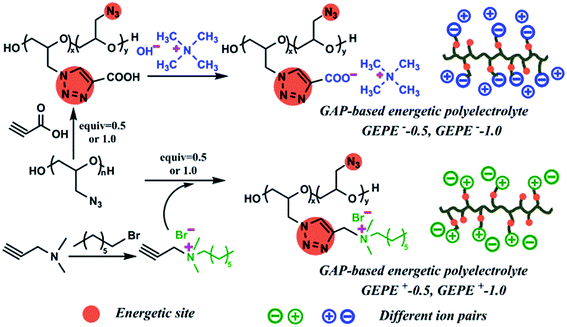
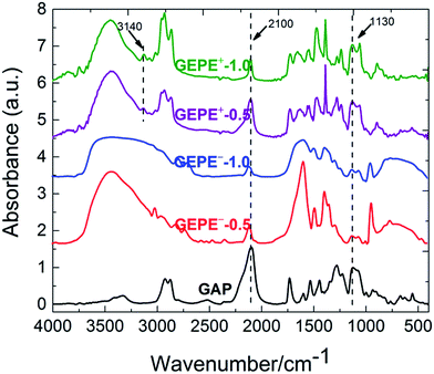
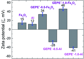
As illustrated in Fig. 1, in order to graft the desired ion pairs onto the GAP backbone, highly regioselective copper-mediated 1,3-dipolar cycloaddition between an azide group and a terminal alkyne, typical “click chemistry”, was adopted, resulting in 1,2,3 triazole rings, due to its feasibility and notable reactivity.20–24 Interestingly, the pristine azide group and the formed triazole are both energetic sites, which are widely used in GAP curing systems as energetic propellant binders with higher heats of exothermic decomposition.20–23 Therefore, the newly-formed polyelectrolytes (GEPEs) maintain the energetic characteristics, which was expected. The structure of the ammonium salt monomer containing alkyne was confirmed by NMR, and the data are shown in Fig. S1a (1H-NMR) and Fig. S1b (13C-NMR) (ESI†). FT-IR spectra of the obtained GAP-based energetic polyelectrolytes (GEPEs) and the as-received GAP are given in Fig. 2. After reaction, the azide residue can be observed in all products, but it is not adverse, as mentioned before. The peaks at 2100 and 1130 cm−1, are assigned to the azide group and vibration of C–O–C in the backbone, respectively.22 The ratios of azide to C–O–C intensity were calculated, and declined with the increase of the feeding amount of monomer containing ion. The signal at 3140 cm−1 is attributed to the C–H vibration in the formed triazole.23 For GEPE−-0.5 and GEPE−-1.0, the peaks of triazole are not obvious because of the covering up of the broad peak of the carboxyl group between 3000 and 3700 cm−1. With respect to the choice of solvent, GAP is soluble in THF, DMF etc., but not in methanol, ethanol and water, etc.; GEPE−-0.5 and GEPE−-1.0 are soluble in methanol, ethanol and water, etc., but not in THF, DMF etc.; GEPE+-0.5 and GEPE+-1.0 are soluble in methanol and ethanol, but not in THF, DMF and water etc. Therefore, ethanol was used as the solvent in the assembly process.When two kinds of oppositely charged polyelectrolytes are mixed together in solution, a polyelectrolyte complex is obtained, as shown in Fig. 3. Fig. 3a (before mixing) and Fig. 3b (after mixing) demonstrate that the assembly of GEPEs is successful, resulting in a GAP-based energetic polyelectrolyte complex (GEPEC). The SEM image of the GEPEC shows that the complex consists of submicron particles and presents porous structures, which is similar to the results of the Jiayin Yuan group.27 GEPEs reach a molecular-level mixing state in ethanol, due to ionic complexation, which is essential because it facilitates a rapid and complete interchain ionic cross-linking, fixing their “frozen” chain conformation and forming submicron particles, as shown in Fig. 3d. Besides, polyelectrolytes could interact strongly with solid substrates, and in turn, they may substantially alter the respective surface characteristics, which are applied to the modification of NPs. To allow for interaction, polyelectrolytes containing carboxyl and ammonium bromide are used to interact with Al NPs and Fe2O3 NPs, respectively, which is attributed to powerful interactions between COO and Al–OH,28 as well as between N and Fe–OH.29 The zeta potentials (ζ) of the modified NPs were analyzed and the results are shown in Fig. 4. The mean values of the ζ of the original NPs range from 10 to 20 mV, which indicates that the colloidal particles are not stable in solution, according to DLVO theory.30 Strikingly, the dispersions of the polyelectrolyte coated NPs tend to be stable, which derives from the absolute values of the ζ being close to, or more than 30 mV. Bearing charges along its backbone, the GEPE coating imparts an additional electrostatic repulsion and steric barrier between NPs to offset the van der Waals attraction. Furthermore, in each case of NPs, the absolute values of the ζ of the modified NPs increase with increasing amounts of ions in the backbone. The more ion pairs existing in the polymer backbone, the more charges are on the surface of the NPs during ionic dissociation.
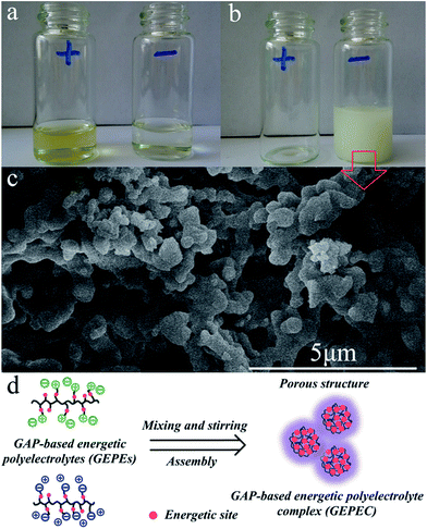 | ||
| Fig. 3 Photos of the GAP-based energetic polyelectrolyte ethanol solution before (a) and after (b) the assembly process. SEM image (c) and illustration (d) of GEPEC. | ||
In a mixed system, the oppositely charged Al and Fe2O3 NPs will assemble into larger aggregates, due to the electrostatic attraction between them.31 For instance, Al NPs can be arranged, directed by electrostatic forces, in a controlled manner around the Fe2O3 NPs or vice versa, leading to a direct, intimate contact between fuel and oxide. The free, oppositely charged polyelectrolytes become a complex, playing the role of an energetic binder in the assembly system.13 Under the low-shear force of stirring that ensures homogeneous mixing, Brownian diffusion co-exists with aggregation, resulting in homogeneity and successful assembly. SEM images of the assembled reactive Al/Fe2O3 microspheres with different amounts of GEPEs (GEPE−-1.0 and GEPE+-1.0) are shown in Fig. 5. More SEM images at lower magnification are presented in Fig. S2.† Microspheres can be observed in these images when the content of GEPEs is 5 wt% (a), 10 wt% (b), 15 wt% (c), and 20 wt% (d). For the different GEPE contents, the dimensions of five hundred of the assembled Al/Fe2O3 microspheres were determined and the distributions were fitted by Gaussian function (Fig. S3†). The diameters of the maximum frequencies of the fitted curves and the corresponding standard errors are depicted in Fig. 6. The average diameter of the assembled Al/Fe2O3 microspheres is about 0.8 μm, when the content of GEPEs is 5 wt%. As the content went over 10 wt%, the average diameters tended to be stable, ranging from 1 μm to 2 μm. GEPE−-0.5 and GEPE+-0.5 were also used to direct the assembly process; however, fewer clearly outlined spheres could be observed (Fig. S4†). The assembly ratio, which refers to what percentage of Al and Fe2O3 assembled into microspheres, was estimated by the method adopted by the Zachariah team6 using ImageJ software.32 The large microspheres were first illuminated against a dark background by inverting the colors. By adjusting the image threshold, the boundaries of the large spheres were sharpened against the background. The area of the microspheres and the background could be obtained and then the assembly ratio was calculated. For the typical Al/Fe2O3 microspheres with GEPE-1.0 content of 10 wt%, the assembly ratios analyzed by the ImageJ are fully provided in the ESI (Fig. S5, Table S1†). The assembly ratios were 42.1%, 58.6%, 61.2%, and 63.5% for the assembled Al/Fe2O3 microsphere with GEPE-1.0 content of 5 wt%, 10%, 15%, and 20%, respectively. For the phenomenon of the changes in the microsphere size and assembly ratio, based on the results of the zeta potential test, we suggest that either smaller amounts of GEPEs in the NPs modification or lower density of ions in GEPEs will present an unsatisfactory assembly process.
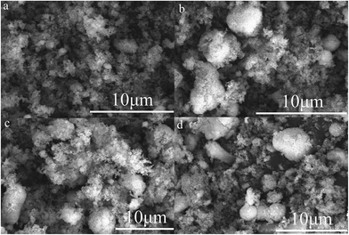 | ||
| Fig. 5 SEM images of assembled reactive Al/Fe2O3 microspheres with GEPEs contents of 5 wt% (a), 10 wt% (b), 15 wt% (c), and 20 wt% (d). | ||
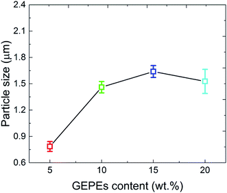 | ||
| Fig. 6 Average diameters of assembled, reactive Al/Fe2O3 microspheres with different GEPEs contents. | ||
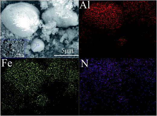
As illustrated in Fig. 7, the EDS test was employed to investigate the dispersity of Al and Fe2O3 in the assembled reactive microspheres. The surfaces of the reactive microspheres are shown in the image, surrounded by the blue square. Here, Al, Fe and N represent the Al NPs, Fe2O3 NPs and GEPEs respectively. From the view of element distribution, the Al and Fe2O3 nanoparticles in particular, have good dispersity in the assembled reactive microspheres. Indeed, the arrangement of NPs is organized and directed by the electrostatic forces between them, which are generated by the GEPEs.
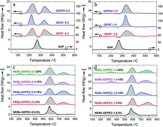
As the GEPE is termed an energetic polyelectrolyte, much attention must be paid to the energy performance. DSC measurements were performed to characterize the thermophysical properties of the GEPE and NEMs prepared in this work, and quantify energy release. Fig. 8 shows the DSC traces of all tested materials and the areas of the shaded parts determine the energy released by the materials during the heating process. In Fig. 8a and b, for the pristine GAP, the exothermic peak at 270 °C is attributed to the scission of azide groups.23 As mentioned above, about half of the azide groups are maintained in the GEPE-0.5 (Fig. 8a); however, the exothermic peaks of these unreacted azide groups appear at about 230 °C, possibly due to the influence of the introduced ion pairs. In the case of GEPE-1.0 (Fig. 8b), there is no distinct exothermic peak of the small amounts of azide groups. The strong exothermic peaks at 330 °C are assigned to the decomposition of the triazole.23 The heat release of the GEPEs is summarized in Table 1. Compared to the energy of the pristine GAP, the energy of GEPEs was reduced by a factor of four and seven for GEPE-0.5 and GEPE-1.0, respectively, due to a large quantity of the incorporation of the inert groups (ion pairs and alkyl chains), which lowered the energy density. DSC curves of the assembled Al/Fe2O3 NEMs directed by GEPE-0.5 and GEPE-1.0 are shown in Fig. 8c and d, respectively. The exothermic peaks before 400 °C relate to the GEPEC, while the peaks after 480 °C are involved in the oxidation–reduction reaction of Al/Fe2O3 NEMs. The exothermic peaks emerge between 480 and 850 °C (with onset temperature at 480 °C), which are divided into two discontinuous parts, due to the endothermic melting peaks of Al at about 660 °C.16,25 The peaks at 580 °C and 760 °C are attributed to the Al reacting with Fe2O3 in solid and molten states, respectively.16,25 The heat release of the assembled reactive Al/Fe2O3 microspheres and the corresponding GEPEC, are summarized in Table 2. In general, the heat release of the assembled Al/Fe2O3 NEMs improved significantly, nearly twice the value of Al/Fe2O3 NEMs prepared by sonication, and the heat release is optimum when the content of GEPEC is 10 wt%. Before the value of 10 wt%, the heat release increased with the increasing GEPEC content because greater GEPEC content could direct a better assembly process and get much more contact points between the Al and Fe2O3 NPs, which was also proved by the change in the microsphere size. If the value is beyond 10 wt%, the heat release decreases with increasing the GEPEC content, due to the energy of GEPEC being far lower than the theoretical value of the Al–Fe2O3 reaction, 3.97 kJ g−1.33 Moreover, the heat release of the NEMs using GEPEC-1.0 is higher, compared to that of the NEMs using GEPEC-0.5, although the energy of GEPEC-0.5 is higher than that of GEPEC-1.0. When the amounts of the two GEPEC are the same, the GEPE-1.0 has more charges and directs the assembly process better, which is also confirmed by the different morphologies of the NEMs using GEPE-0.5 and GEPE-1.0 (microspheres) respectively. Additionally, it is worth noting that the nanoparticles are pyrophoric, but only when in sufficiently high concentrations. An isolated nanoparticle in air will not burn because of rapid heat loss to the surroundings. The well assembled microsphere, in effect, constrains the heat released within a small volume, which promotes acceleration of the global reaction.
| Materials | Heat release (J g−1) | Materials | Heat release (J g−1) |
|---|---|---|---|
| Pristine GAP | 4560 | Pristine GAP | 4560 |
| GEPE−-0.5 | 1120 | GEPE−-1.0 | 610 |
| GEPE+-0.5 | 987 | GEPE+-1.0 | 685 |
| GEPEC-0.5 | 1054 | GEPEC-1.0 | 672 |
| Materials | Heat release (J g−1) | Materials | Heat release (J g−1) | ||||
|---|---|---|---|---|---|---|---|
| GEPEC-0.5 | Al/Fe2O3 | Total | GEPEC-1.0 | Al/Fe2O3 | Total | ||
| NEMs-0% | — | 876 | 876 | NEMs-0% | — | 876 | 876 |
| NEMs-5% | 69 | 1185 | 1254 | NEMs-5% | 30 | 1320 | 1350 |
| NEMs-10% | 126 | 1488 | 1614 | NEMs-10% | 78 | 1860 | 1938 |
| NEMs-15% | 148 | 1423 | 1551 | NEMs-15% | 154 | 1517 | 1671 |
| NEMs-20% | 202 | 1293 | 1495 | NEMs-20% | 141 | 1242 | 1383 |
To study the relative reactivity of the NEMs, a fixed mass (25 mg) of the loose NEMs powder was placed in a constant-volume pressure cell (about 13 mL) and ignited by resistive heating of a nichrome wire. The dynamic pressure signals were captured simultaneously using a digital oscilloscope. In a typical, representative pressure trace, the maximum pressure (Pmax), rise time and pressurization rate were obtained, which are illustrated in Fig. 9a. The pressurization rate is reported as a relative measurement of the reactivity and has been shown to experimentally correlate with flame propagation rates, and is thus considered to be somehow proportional to the reaction rate. Each sample was evaluated in triplicate and the average Pmax, rise time and pressurization rates as a function of GEPEC content, as well as the corresponding standard deviations, are reported in Fig. 9b–d. The typical pressure–time profiles of the NEMs are provided in Fig. S6.† Both Pmax and pressurization rate show a significant increase with increasing GEPEC content up to 10 wt%, where the microsphere particles have maximum pressures and pressurization rates, and a decline when the GEPEC content is above 10 wt%. These results are consistent with the conclusion of the heat release in the DSC test. However, the rise time shows a reverse trend, due to the different reactivity. The larger the slope, the higher the reactivity between the oxidizer and the fuel, and the shorter is the rise time. More importantly, the performance of the Al/Fe2O3 NEMs using GEPEs-1.0 reactive microspheres, is superior to that of the Al/Fe2O3 NEMs using GEPEs-0.5 without regular shape, although they are chemically similar. This is not surprising since the well assembled reactive Al/Fe2O3 microsphere could accumulate the heat within the microstructure while promoting the mass transport at the same time, leading to a self-accelerating behavior.13,36–38 The dynamic pressure results of the reactive Al/Fe2O3 microspheres in this work are compared with all other Al/Fe2O3 NEMs shown in the literature and summarized in Table 3. It is observed from the table that the pressurization rate of the reactive Al/Fe2O3 microspheres is the highest value so far, even two orders of magnitude higher than that of many Al/Fe2O3 NEMs. It is widely accepted that the interfacial contact between the fuel and oxide plays an important role in the combustion performance of NEMs. The assembly process directed by the GEPEs bears the burden of this role successfully. However, according to the reports of the Zachariah team,13,36–38 this is not the only reason. GEPEs function beyond the role as a modifier to also serve as a gas generator because of the decomposition of energetic sites at low temperature.24,39 The creation of a Al/Fe2O3 microsphere by incorporating a gas generator weakens the adverse sintering, thereby preserving the nanostructure longer during the combustion event. To confirm this point, the morphology of the combustion products of the Al/Fe2O3 NEMs was examined by SEM (Fig. S7†). The average diameters of combustion products of the assembled Al/Fe2O3 microspheres and Al/Fe2O3 NEMs prepared by sonication are 1.8 μm and 9.3 μm, respectively. The average dimension of the combustion product of the assembled Al/Fe2O3 microspheres is much smaller than that of the Al/Fe2O3 NEMs prepared by sonication, which is in agreement with the results of the Zachariah team.13,36–38 Additionally, at low GEPEC content, the performance is improved with increasing the GEPEC content, possibly due to the presence of a ready source of low temperature, energetic, generating gas so as to minimize nanostructure loss. At higher loading, performance degrades mainly because the total energy is degraded by a large margin, which is the basis of the NEMs.
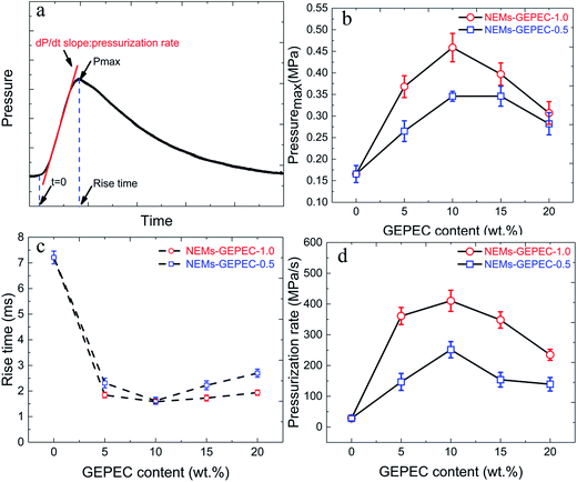 | ||
| Fig. 9 A typical representative pressure trace (a). Maximum pressure (b), rise time (c) and pressurization rate (d) of NEMs using GEPEC-1.0 and GEPEC-0.5, with different contents. | ||
| Sample | Method | Dynamic pressure results | Reference | ||
|---|---|---|---|---|---|
| Pmax (MPa) | Rise time (s) | Pressurization rate (MPa s−1) | |||
| nAl/Fe2O3 nanotube | Solvent-mixed | 0.107 | 0.338 | 2.50 | 9 and 10 |
| nAl/nFe2O3 | Solvent-mixed | 0.749 | 0.22 | 34.05 | 34 |
| nAl/nFe2O3 | Solvent-mixed | 0.19 | 0.057 | 33.33 | 16 |
| nAl/nFe2O3 | Solvent-mixed | 0.089 | — | 117 | 26 and 35 |
| nAl/nFe2O3 | Solvent-mixed | 0.092 | 0.0008 | 116 | 40 |
| nAl/nFe2O3 | Solvent-mixed | 0.06 | — | 20 | 41 |
| nAl/Fe2O3 nanotube | Self-assembled | 0.18 | 0.207 | 6.403 | 9 and 10 |
| nAl/nFe2O3 | Self-assembled | 2.280 | 0.2774 | 82.19 | 34 |
| nAl/nFe2O3/MWCNT | Self-assembled | 0.37 | 0.0035 | 105.71 | 16 |
| nAl/nFe2O3 microsphere | Self-assembled | 0.46 | 0.0016 | 410.36 | This work |
4. Conclusion
In summary, GAP-based energetic polyelectrolytes (GEPEs) with positive and negative charges respectively, were successfully prepared by “click chemistry”; both the reactants and resultant products are energetic polymers. We demonstrated the electrostatic assembly as a facile way to fabricate high performance reactive Al/Fe2O3 microspheres with the GEPEs acting as the directing agent. Greater amounts of the ion pairs tethered to the GEPEs and more content of the GEPEs used in the assembly process favor the formation of reactive microspheres. When the content of GEPEs is under 10 wt%, the performance of the obtained reactive microspheres is enhanced as the content of GEPEs increases. In this study, the GEPEs offer potential advantages. GEPEs act as a modifier, interacting strongly with NPs and improving the intimacy of the fuel and oxide via powerful electrostatic attraction between the modified NPs. Internal gas released by the decomposition of energetic sites existing inside the assembled microspheres, separates the NPs rapidly to prevent adverse sintering, weakening the nanostructure loss during reaction. As a consequence, it is reasonable to conclude that the assembly with the GEPEs directing agent is a feasible and effective approach to achieving the acquisition and exploration of high performance NEMs.Conflict of interest
The authors declare that they have no conflict of interest.References
- X. Zhou, M. Torabi, J. Lu, R. Shen and K. Zhang, ACS Appl. Mater. Interfaces, 2014, 6, 3058–3074 CAS.
- C. Rossi, Propellants, Explos., Pyrotech., 2014, 39, 323–327 CrossRef CAS.
- G. C. Egan, K. T. Sullivan, T. LaGrange, B. W. Reed and M. R. Zachariah, J. Appl. Phys., 2014, 115, 084903 CrossRef.
- P. Chakraborty and M. R. Zachariah, Combust. Flame, 2014, 161, 1408–1416 CrossRef CAS.
- K. T. Sullivan, N. W. Piekiel, C. Wu, S. Chowdhury, S. T. Kelly, T. C. Hufnagel, K. Fezzaa and M. R. Zachariah, Combust. Flame, 2012, 159, 2–15 CrossRef CAS.
- R. J. Jacob, G. Jian, P. M. Guerieri and M. R. Zachariah, Combust. Flame, 2015, 162, 258–264 CrossRef CAS.
- G. C. Egan, T. LaGrange and M. R. Zachariah, J. Phys. Chem. C, 2015, 119, 2792–2797 CAS.
- S. H. Kim and M. R. Zachariah, Adv. Mater., 2004, 16, 1821–1825 CrossRef CAS.
- J. L. Cheng, H. H. Hng, H. Y. Ng, P. C. Soon and Y. W. Lee, J. Phys. Chem. Solids, 2010, 71, 90–94 CrossRef CAS.
- J. L. Cheng, H. H. Hng, Y. W. Lee, S. W. Du and N. N. Thadhani, Combust. Flame, 2010, 157, 2241–2249 CrossRef CAS.
- J. Y. Malchi, T. J. Foley and R. A. Yetter, ACS Appl. Mater. Interfaces, 2009, 1, 2420–2423 CAS.
- F. Séverac, P. Alphonse, A. Estève, A. Bancaud and C. Rossi, Adv. Funct. Mater., 2012, 22, 323–329 CrossRef.
- H. Wang, G. Jian, G. C. Egan and M. R. Zachariah, Combust. Flame, 2014, 161, 2203–2208 CrossRef CAS.
- C. Weir, M. L. Pantoya, G. Ramachandran, T. Dallas, D. Prentice and M. Daniels, J. Electrost., 2013, 71, 77–83 CrossRef CAS.
- C. Weir, M. L. Pantoya and M. A. Daniels, Combust. Flame, 2013, 160, 2279–2281 CrossRef CAS.
- T. Zhang, Z. Ma, G. Li, Z. Wang, B. Zhao and Y. Luo, J. Solid State Chem., 2016, 237, 394–403 CrossRef CAS.
- P. Maroni, F. J. Montes Ruiz-Cabello, C. Cardoso and A. Tiraferri, Langmuir, 2015, 31, 6045–6054 CrossRef CAS PubMed.
- J. J. Hu, Y. H. Hsieh and J. S. Jan, J. Colloid Interface Sci., 2015, 438, 94–101 CrossRef CAS PubMed.
- J.-P. Chapel and J.-F. Berret, Curr. Opin. Colloid Interface Sci., 2012, 17, 97–105 CrossRef CAS.
- S. Reshmi, K. P. Vijayalakshmi, D. Thomas, R. Rajeev and C. P. Reghunadhan Nair, Combust. Flame, 2016, 167, 380–391 CrossRef CAS.
- S. Reshmi, E. Arunan and C. P. R. Nair, Ind. Eng. Chem. Res., 2014, 53, 16612–16620 CrossRef CAS.
- D.-H. Lee, K. T. Kim, Y. Jang, S. Lee, H. B. Jeon, H.-j. Paik, B. S. Min and W. Kim, J. Appl. Polym. Sci., 2014, 131, 4401–4404 Search PubMed.
- S. K. Reshmi, K. P. Vijayalakshmi, D. Thomas, E. Arunan and C. P. Reghunadhan Nair, Propellants, Explos., Pyrotech., 2013, 38, 525–532 CrossRef CAS.
- S. Reshmi, H. Hemanth, S. Gayathri and C. P. Reghunadhan Nair, Polymer, 2016, 92, 201–209 CrossRef CAS.
- T. Zhang, Z. Wang, G. Li and Y. Luo, J. Solid State Chem., 2015, 230, 1–7 CrossRef CAS.
- C. Wu, K. Sullivan, S. Chowdhury, G. Jian, L. Zhou and M. R. Zachariah, Adv. Funct. Mater., 2012, 22, 78–85 CrossRef CAS.
- Q. Zhao, P. Zhang, M. Antonietti and J. Yuan, J. Am. Chem. Soc., 2012, 134, 11852–11855 CrossRef CAS PubMed.
- K. S. Kappagantula, C. Farley, M. L. Pantoya and J. Horn, J. Phys. Chem. C, 2012, 116, 24469–24475 CAS.
- B. I. Kharisov, H. V. R. Dias, O. V. Kharissova, A. Vázquez, Y. Peña and I. Gómez, RSC Adv., 2014, 4, 45354–45381 RSC.
- Z. Adamczyk and P. Weronski, Adv. Colloid Interface Sci., 1999, 83, 137–226 CrossRef CAS.
- D. A. Walker, B. Kowalczyk, M. O. de la Cruz and B. A. Grzybowski, Nanoscale, 2011, 3, 1316–1344 RSC.
- ImageJ, http://rsb.info.nih.gov/ij/.
- S. H. Fischer and M. C. Grubelich, Presented in part at the 24th International Pyrotechnics Seminar, Monterey, CA, 1998 Search PubMed.
- X.-Q. Wang, L. Zhang, S.-G. Zhu and J. Zhao, Chin. J. Inorg. Chem., 2013, 29, 1799–1804 CAS.
- K. Sullivan and M. R. Zachariah, J. Propul. Power, 2010, 26, 467–472 CrossRef CAS.
- G. Young, H. Wang and M. R. Zachariah, Propellants, Explos., Pyrotech., 2015, 40, 413–418 CrossRef CAS.
- R. J. Jacob, B. Wei and M. R. Zachariah, Combust. Flame, 2015, 167, 472–480 CrossRef.
- H. Wang, G. Jian, S. Yan, J. B. DeLisio, C. Huang and M. R. Zachariah, ACS Appl. Mater. Interfaces, 2013, 5, 6797–6801 CAS.
- M. A. Hobosyan, S. A. Yolchinyan and K. S. Martirosyan, RSC Adv., 2016, 6, 66564–66570 RSC.
- J. Feng, G. Jian, Q. Liu and M. R. Zachariah, ACS Appl. Mater. Interfaces, 2013, 5, 8875–8880 CAS.
- H. Wang, G. Jian, W. Zhou, J. B. DeLisio, V. T. Lee and M. R. Zachariah, ACS Appl. Mater. Interfaces, 2015, 7, 17363–17370 CAS.
Footnote |
| † Electronic supplementary information (ESI) available. See DOI: 10.1039/c6ra24857h |
| This journal is © The Royal Society of Chemistry 2017 |

