
Recent progress in conversion reaction metal oxide anodes for Li-ion batteries
Kangzhe
Cao†
a,
Ting
Jin†
a,
Li
Yang
a and
Lifang
Jiao
 *ab
*ab
aKey Laboratory of Advanced Energy Materials Chemistry (Ministry of Education), College of Chemistry, Nankai University, Tianjin 300071, China. E-mail: jiaolf@nankai.edu.cn
bCollaborative Innovation Center of Chemical Science and Engineering (Tianjin), Tianjin 300071, China
First published on 26th June 2017
Abstract
Transition metal oxides (TMOs) based on conversion reactions are attractive candidate anode materials for lithium-ion batteries (LIBs) because of their high theoretical capacity and safety characteristics. In this review, we have summarized recent progress in the rational design and efficient synthesis of TMOs with controllable morphologies, compositions, and micro-/nanostructures, along with their Li storage behaviors. Single metal oxides of manganese (Mn), iron (Fe), cobalt (Co), nickel (Ni), copper (Cu), ruthenium (Ru), chromium (Cr), molybdenum (Mo), and tungsten (W) and their common binary metal oxides have been discussed in this review. Finally, the less well-known merits of conversion reactions are put forward, and the design of metal oxide electrodes making full use of these merits has been proposed.
 Kangzhe Cao | Kangzhe Cao received his BSc from Henan Normal University (Henan, China) in 2012 and his PhD from Nankai University (Tianjin, China) in 2017 under the supervision of Assoc. Prof. Lifang Jiao and Prof. Yijing Wang. His research interests focus on the development of advanced materials for electrochemical energy storage (Li/Na-ion batteries and Li–S batteries). |
 Ting Jin | Ting Jin was born in Shaanxi, China, in 1994. She received her BSc degree in materials chemistry from Northwest University (China) in 2015. Currently, she is a PhD student in the group of Assoc. Prof. Lifang Jiao at Nankai University (China). Her research interests focus on the design and fabrication of high-performance electrode materials for lithium-ion and sodium-ion batteries. |
 Lifang Jiao | Lifang Jiao is an Associate Professor at Nankai University, China. She received her PhD degree from Nankai University (China) in 2005. She has co-authored over 180 relevant peer-reviewed publications. Her current research is focused on energy conversion and storage (including lithium, sodium, and magnesium secondary batteries and supercapacitors), hydrogen storage materials and electrocatalytic hydrogen evolution. |
1. Introduction
The increasing demand for clean and sustainable energy has facilitated the development of energy storage systems (ESSs) with large capacities.1 Without these ESSs, many green energy sources, such as solar, wind and waves, cannot be fully utilized due to their instability. Moreover, portability and high energy density of these systems are becoming increasingly important for their application in electric vehicles (EVs), hybrid electric vehicles (HEVs), and small portable devices. Li ion batteries (LIBs) are considered to be the most promising ESSs; they have been used to power the abovementioned applications. Since rocking-chair configurations were commercialized by Sony in 1991, LIBs have dominated the consumer electronic market due to their high energy density, lack of memory effects, long life span, and low self-discharge; currently, they remain popular. However, the limited capacity of current LIBs cannot meet the intense demand for high capacity. A significant reason for this situation is that the theoretical capacity of the electrode materials is not sufficiently high. For example, the theoretical capacity of the graphite currently used in commercial LIBs is only 372 mA h g−1. Therefore, it is highly necessary to develop novel anode materials with large capacities.2The theoretical capacity of a material used for LIBs is related to the number of transferred electrons in its electrochemical reactions and can be calculated by eqn (1):
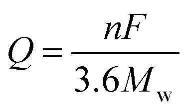 | (1) |
![[thin space (1/6-em)]](https://www.rsc.org/images/entities/char_2009.gif) 500 C mol−1), n is the number of transferred electrons in the electrochemical reaction, and Mw is the equivalent molecular weight. It is clear that the theoretical capacity of an active material is in inverse proportion to the Mw and is proportional to the electron transfer number. Essentially, active materials with multiple-electron reactions and low Mw can achieve high specific capacities.
500 C mol−1), n is the number of transferred electrons in the electrochemical reaction, and Mw is the equivalent molecular weight. It is clear that the theoretical capacity of an active material is in inverse proportion to the Mw and is proportional to the electron transfer number. Essentially, active materials with multiple-electron reactions and low Mw can achieve high specific capacities.
Upon discharging and charging, Li ions are shuttled between the anode and cathode through the electrolyte, and the electrons are transferred through the external circuit. It is clear that the electrons and Li ions should reach the same active site in the electrode material at the same moment to complete the energy transformation between chemical energy and electrical energy.3 This process determines the power density of LIBs, which involves a kinetic problem in the electrode. Li ion diffusion in the electrode mainly consists of two parts: diffusion in the electrolyte and solid-state diffusion in the electrode material. The latter is the key step. As depicted in eqn (2),
| τeq = L2/D | (2) |
In terms of the reaction mechanism, LIBs anode materials can be mainly divided into three types. (1) Li insertion/deinsertion materials. These materials, which react with Li by insertion and deinsertion processes, usually deliver limited capacity; they include graphite (372 mA h g−1) and Li4Ti5O12 (175 mA h g−1). (2) Li-alloying materials. These materials can form Li-alloy compounds after lithiation and always exhibit high specific capacity by transferring multi-electrons. For example, Si anode delivers a theoretical specific capacity of 4211 mA h g−1, and P anode can form Li3P and delivers a capacity of 2594 mA h g−1. However, extreme volume expansion cannot be avoided (about 400% volume expansion for the formation of Li22Si5),5 and this can destroy the electrode structure. (3) Conversion reaction materials. Trascon's group discovered this new Li storage mechanism and firstly used CoO particles as a concept to illustrate it.6
As depicted in Fig. 1a and b, the original CoO particles were highly crystallized, with dimensions of about 100 to 200 nm. After lithiation, the CoO particles disintegrated into 1 to 2 nm nanoparticles and lost their crystallinity, although their initial shapes were preserved. This phenomenon suggests that a nanosize effect exists in this conversion reaction, as indicated by Fig. 1c and d. Moreover, the nanosized character of the electrode is preserved in the following charge, as demonstrated by Fig. 1e and f. These results confirmed that the formed Co nanoparticles were dispersed in a lithia (Li2O) matrix during discharge and were then reoxidated to CoO nanoparticles during charge. This pioneering work opens new territory for materials that hold Li beyond the Li insertion/deinsertion and Li-alloying processes. Since then, numerous efforts have been devoted to this field, and many other conversion reaction materials, such as sulfide, have been found.7
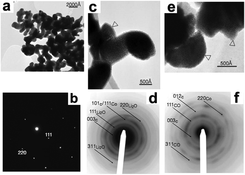 | ||
| Fig. 1 TEM images (a, c and e) and their corresponding selected-area electron diffraction (SAED) patterns (b, d and f) of the starting CoO electrode (a and b), the fully lithiated CoO electrode (c and d), and the delithiated CoO electrode (e and f). Reproduced with permission.6 Copyright 2000, Nature Publishing Group (NPG). | ||
The conversion reaction occurs based on a displacement reaction that can be generalized as the following reaction (eqn (3)):
| MaXb + (b·n)Li+ + (b·n)e− ↔ aM + bLinX | (3) |
Among these conversion reaction materials, transition metal oxides (TMOs) feature high corrosion resistance and facile operation in addition to their high specific capacities. Furthermore, many materials, such as Mn oxides9 and Fe oxides,10 are more attractive due to their high natural abundance and low price.1 However, these TMO electrodes suffer from drawbacks that hinder their applications.
1.1. The challenges and solutions of conversion reaction electrodes
Low electronic conductivity, volume expansion during cycling, and voltage hysteresis are the three main issues facing TMO materials. The low electronic conductivity limits the transfer of electrons and hinders improvement of the rate capability of the electrode. Volume expansion damages the structures of the active materials, resulting in decayed capacity and inferior cycling stability. Voltage hysteresis, which is observed between discharging and charging potential, leads to low energy efficiency. However, whether this hysteresis originates from kinetics or thermodynamics contributions is still in debate.11–14 Currently, researchers are mainly concentrating on improving electrochemical performance, such as the obtained specific capacity, cycling stability, and rate capability. Three approaches are usually adopted with joint application methods.In this review, an overview of recent progress towards conversion reaction TMO electrodes for LIBs is provided, including single metal oxides and binary metal oxides. Specifically, we will focus on the rational structural design and enhanced electrochemical performance of these electrodes. Future prospects in the design of advanced anodes and other functional materials by taking advantage of the merits of conversion reactions are highlighted. All potentials in this review are given versus Li+/Li unless otherwise specified.
2. Single metal oxides
2.1. Manganese oxides
Manganese oxides, including MnO, Mn3O4, Mn2O3, and MnO2, feature high specific capacities, low electrochemical motivation forces (1.032 V vs. Li+/Li), environmentally benign natures, and low cost; they are being considered for use as alternative LIB anode materials.26–28 The general consensus is that Mn metal nanoparticles are formed after lithiation of these oxides; thus, the theoretical specific capacities of these MnOx anodes are 756, 937, 1018, and 1232 mA h g−1, respectively. However, the oxidation production of these materials are controversial. In terms of MnO and Mn3O4 anodes, the Mn nanoparticles can be reoxidated to their original oxidation states with high reversibility. The Li storage behaviors of these anodes can be described as follows:| MnO + 2Li+ + 2e− ↔ Mn + Li2O | (4) |
| Mn3O4 + 8Li+ + 8e− ↔ 3Mn + 4Li2O | (5) |
Meanwhile, the reoxidized product of Mn2O3 anodes is in debate. One suggestion is that MnO is the oxidation product of Mn2O3 anodes at 3.0 V, as described in the following equations:29,30
| 3Mn2O3 + 2Li+ + 2e− → 2Mn3O4 + Li2O | (6) |
| Mn3O4 + Li+ + e− → LiMn3O4 | (7) |
| LiMn3O4 + Li+ + e− → 3MnO + Li2O | (8) |
| MnO + 2Li+ + 2e− ↔ Li2O + Mn | (9) |
Another view is that Li+ storage behavior in Mn2O3 nanoplate anodes proceeds as follows:31,32
| 2Li+ + 3Mn2O3 + 2e− → 2Mn3O4 + Li2O | (10) |
| 2Li+ + Mn3O4 + 2e− → 3MnO + Li2O | (11) |
| 2Li+ + MnO + 2e− ↔ Li2O + Mn | (12) |
| xLi2O + Mn ↔ 2xLi+ + MnOx + 2xe− (1.0 < x < 1.5) | (13) |
MnO2 is known to have many polymorphs; they are often studied as LIB cathodes, catalysts, biosensors, and supercapacitors.33–36 When used as LIB anodes, the oxidation product is vague, although it has been the subject of many studies.37–39 Therefore, further research to detect Li+ storage behavior in Mn2O3 and MnO2 anodes is urgent and meaningful.
Due to the limitation of low solid Li ion diffusion rates, Mn oxides with various morphologies and micro-/nano-structures have been rationally designed to facilitate ion diffusion in order to achieve satisfactory electrochemical performance. Porous structure electrodes, such as MnO nanowires,40 Mn2O3 nanowires,41 Mn2O3 nanoplates,31,42 Mn2O3 microspheres,43 Mn2O3 derived from Mn-based MOFs,44 Mn2O3 hollow boxes,45 Mn3O4 nanotubes,46 and hierarchical MnO2/C hybrid spheres,38 have been designed and fabricated as LIB anodes. By virtue of their numerous different-sized voids, which facilitate electrolyte infiltration and Li+ ion diffusion, these electrodes exhibit high electrochemical performance. For example, a porous Mn2O3 nanoplate anode exhibits a capacity of 813.7 mA h g−1 after 50 cycles at a current density of 0.1 A g−1 as reported by Zhang et al.31 A porous Mn2O3 anode using a MOF precursor delivers a reversible capacity of 705 mA h g−1 at 1.0 A g−1 even after 250 cycles.44 Fabricating hollow structures is considered to be another effective way to alleviate structural strain on the electrode during cycling. Single shell hollow spheres,47,48 multi shell hollow spheres,49 and hollow porous MnO/C microspheres50 have been synthesized and used as high-performance LIB anodes. Selected typical morphologies of MnOx are listed in Fig. 2.
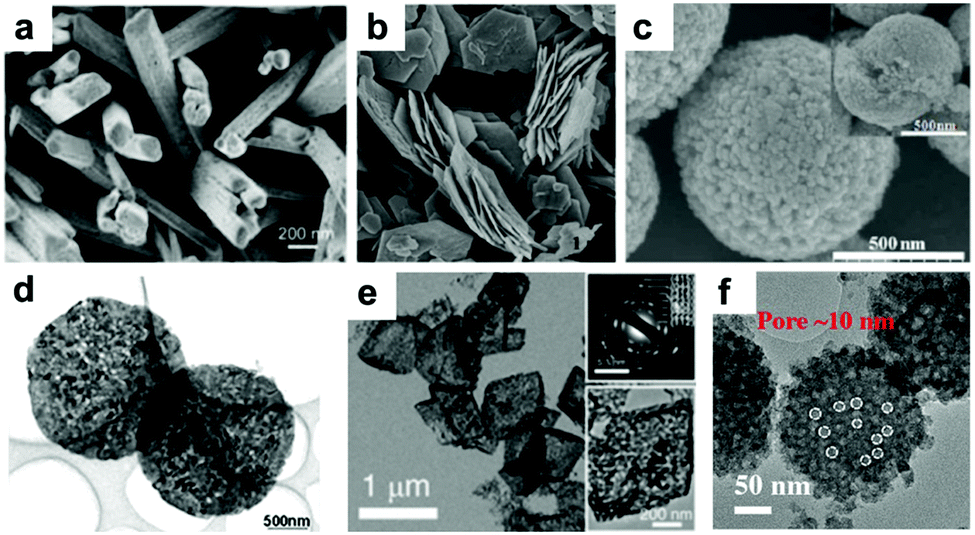 | ||
| Fig. 2 SEM images of (a) Mn2O3 NWs, (b) Mn2O3 nanoplates, and (c) Mn2O3 microspheres; TEM images of (d) Mn2O3 nanoplates, (e) Mn2O3 porous hollow boxes, and (f) hierarchical MnO2/C hybrid spheres. (a–f) are reproduced with permission. (a),41 Copyright 2014, ACS; (b),42 Copyright 2014, RSC; (c),43 Copyright 2013, RSC; (d),31 Copyright 2014, Wiley; (e),45 Copyright 2015, RSC; (f),38 Copyright 2016, Wiley. | ||
Recently, our group fabricated mini-hollow polyhedron Mn2O3 using Mn-based MOFs as precursors.26 This mini-hollow structure differs from conventional hollow structures with large interiors, which endows the as-prepared polyhedron Mn2O3 with high performance in LIB anodes. As shown in Fig. 3a, the high-angle annular dark-field scanning transmission electron microscope (HAADF-STEM) image suggests that the hollow structure contains a mini-hollow cavity and thick shell, in contrast to familiar hollow structures with large interior hollow cavities and thin shells.47,48,51–53 The TEM image in Fig. 3b suggests that the mini-hollow cavity of the original polyhedron Mn2O3 disappears and the smooth shell becomes rough after cycling. Fig. 3c confirms that a reformation process has occurred in the mini-hollow polyhedron Mn2O3, and a hierarchical nanostructure consisting of reformatted nanoparticles is formed. The cycling performance in Fig. 3d displays that the mini-hollow Mn2O3 anode achieves super-long cycling stability and high capacity (a capacity of 819.8 mA h g−1 is obtained after 1200 cycles at 1.0 A g−1), while the bulk anode shows limited cycling performance (160 mA h g−1 is retained after 250 cycles). The main reason for the outstanding electrochemical properties demonstrated by the mini-hollow Mn2O3 electrode is that the unique mini-hollow structure can utilize the merits induced by the nanosize effect. As typical features of conversion reactions, nanosize effects and volume expansion cannot be avoided. Fortunately, the small interior cavity offers space for inward volume expansion that is filled by the reformed nanoparticles, constructing a hierarchical nanostructure with a homogeneous dispersion of nanoparticles, as illustrated in Fig. 3e. Therefore, the reconstructed nanostructures possess the merits of short Li diffusion distance, more active sites, and stable structure, showing satisfactory electrochemical performance without any serious “electrochemical sintering” after long cycling. The size of the hollow cavity may not be optimal; however, as the authors point out, the concept of a mini-hollow structure can offer a new concept in designing rational structures to exploit the merits of nanosize effects.
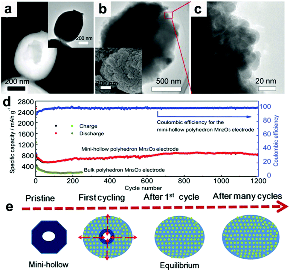 | ||
| Fig. 3 (a) HAADF-STEM and TEM images (inset) of the original mini-hollow Mn2O3; TEM images (b and c) and SEM image (inset in b) of mini-hollow Mn2O3 after the first cycle, (d) cycling performance of mini-hollow Mn2O3 and bulk Mn2O3 at 1.0 A g−1, (e) schematic of the structure evolution of mini-hollow Mn2O3 electrodes with cycling. Reproduced with permission.26 Copyright 2016, Wiley. | ||
Mai and co-workers designed a manganese oxide/carbon yolk–shell structure to enhance the electronic conductivity of the composite and alleviate the effects of volume expansion of the active materials during cycling.54 The hollow space around the manganese oxide allows it to expand without damaging the overall morphology during cycling, while the carbon shell is beneficial to fast electron transfer and the stability of the SEI layers. Thus, their yolk–shell anode exhibits a capacity of 634 mA h g−1 after 900 cycles at 0.5 A g−1. Jiang et al. reported a peapod-like MnO/C heterostructure anode.55 The nano-peapod structure has an internal void space, which is sufficient to restrain volume expansion without cracking the carbon layer, hence preserving the structural integrity. Therefore, the peapod-like MnO/C anode exhibits outstanding cycling stability and rate capability (no capacity fading after cycling 1000 times at 2.0 A g−1, and a capacity of 463 mA h g−1 at 5.0 A g−1). Additionally, MnOx–C hybrid materials, in which MnOx nanoparticles are embedded in porous carbon,56–58 carbon nanosheets,59 and carbon nanofibers,60 have been fabricated and used as high performance LIB anodes. Interestingly, most of these electrodes show increasing capacities as cycling proceeds. Several factors account for this phenomenon, including the increased number of active sites introduced by nanosize effects, higher oxidation state products, interfacial Li storage (pseudocapacitance), and the growth of an electrochemical gel-like polymer layer.26,54,56 Interestingly, the factor of increasing capacity could be adopted to design high performance electrodes. A new rGO–MnO–rGO sandwich nanostructure anode was fabricated by Yuan et al. and achieved outstanding rate capability (379 mA h g−1 after 4000 cycles at 15 A g−1, 331.9 mA h g−1 at 40 A g−1) with unprecedented cycle stability owing to the synergistic effect of the surface pseudocapacitance and diffusion-controlled lithium storage.61
MnOx anodes not only show excellent electrochemical performance in half cells but also exhibit remarkable performance when applied in Li-ion full cells.41,62,63 Wang et al. reported Mn-based flexible LIB full cells using an Mn2O3 anode and a LiMn2O4 cathode which were synthesized using MnOOH nanowires grown on Ti foil as the precursor.41 The Mn2O3 anode delivers a capacity of 502.3 mA h g−1 after 100 cycles, while the LiMn2O4 cathode maintains a reversible capacity of 94.7 mA h g−1 at 0.1 A g−1 after 100 cycles in half cells. When a LIB full cell is fabricated using these two electrodes, a specific capacity of 99 mA h g−1 is obtained based on the mass of the cathode material. The output voltage of the full cell can turn on a 3 V light emitting diode (LED, 10 mW), showing its potential practical applications. Wei's group fabricated a MnO@C‖LiMn2O4 full cell using a MnO@C core–shell nanowires anode.62 As depicted in Fig. 4a, the MnO cores are coated with uniform carbon shells, and many internal void spaces are retained in the hybrid MnO@C nanowires. It is believed that the uniform carbon shells enhance the conductivity and the internal void spaces along the 1D configuration can accommodate volumetric expansion of MnO during lithiation. The extraordinary cycling performance of the MnO@C core–shell nanowires anode is illustrated in Fig. 4b. Obviously, little capacity decay can be seen at a current density of 1.0 A g−1 for 200 cycles. The full cell assembled from the as-prepared MnO/C anode and LiMn2O4 nanoparticle cathode is illustrated in Fig. 4c. The electrochemical reactions on the two electrodes at charge and discharge are believed to proceed as follows:
| (x/2)MnO/C + LiMn2O4 ↔ (x/2)Li2O + (x/2)Mn/C + Li1−xMn2O4 | (14) |
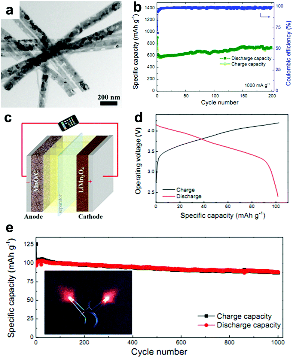 | ||
| Fig. 4 (a) TEM image and (b) cycling performance at 1.0 A g−1 of MnO@C nanowires. (c) Schematic and (d) charge/discharge curves of the MnO@C‖LiMn2O4 full cell. (e) Cycling performance of the full cell at 0.2 A g−1. The insets of (e) show the lighting of two red LEDs by the full cell. Reproduced with permission.62 Copyright 2016, Elsevier. | ||
As shown in Fig. 4d, the output average voltage of the full cell is about 3.6 V, and a discharge capacity of 104 mA h g−1 at 1.4 C (1 C = 148 mA h g−1) is delivered. More importantly, the capacity retains 87% of its maximum value after 1000 cycles (Fig. 4e), indicating the outstanding cycling stability of the full cell. Encouragingly, the rate capability is also excellent. When the full cell is cycled at high rates of 6.8 C and 13.5 C, the capacity can still reach 72.7% and 63.6% of the capacity at 0.17 C. More importantly, the capacity of the full cell can be completely recovered if the current density is returned to 0.17 C. This excellent rate capability may have a positive effect on the practical application of Mn oxides. A flexible rGO/Mn3O4‖LiMn2O4 full battery was also assembled by this group.63 They prepared long Mn3O4 nanowires and hybridized them with rGO using a facile vacuum filtration method. The strong interaction between the long Mn3O4 nanowires and large-area rGO not only enables the as-prepared rGO/Mn3O4 membrane to endure various mechanical deformations, such as bending, twisting, and even folding multiple times, but also offers a strong synergistic effect of enhanced electrochemical reaction kinetics by reducing electron/ion transport resistance and providing an enlarged electrode/electrolyte contact area. When coupled with a LiMn2O4/Al foil cathode, the assembled full cell can power a red light-emitting-diode (LED) in both flat and bended states. Additionally, the full cell exhibits good cycling performance, with a specific capacity of 79 mA h g−1 being retained after 100 cycles.
2.2. Iron oxides
Iron oxides, including FeO, Fe2O3, and Fe3O4, have attracted particular attention for their abundance, non-toxicity, low processing cost, and high capacities when used as LIB anode materials. They achieve high specific capacities of 745, 1007, and 928 mA h g−1 by delivering 2, 6, and 8 mol electrons per mole of material, respectively. Due to these merits, iron oxides are promising LIB anode materials; Lou's group summarized them in 2013.10 Recently, numerous papers on the material synthesis and electrochemical activity of FeOx anodes have been presented.In order to inhibit the volume expansion of FeOx, various structures have been constructed, such as Fe2O3 nano-assembled spindles,65 porous Fe2O3 nanocubes,66 3D mesostructured Fe2O3,13 Fe2O3 hollow microcubes,67 multi-shell Fe2O3 hollow spheres,53 self-assembled Fe3O4 nanoparticle clusters,68 and hierarchical Fe3O4 hollow microspheres.51,52 With this designed internal porosity to inhibit volume expansion, these electrodes always show enhanced cycling stability at low current densities. Chen et al. synthesized Fe2O3 nanotubes and nanorods and compared their lithium-storage performances.69 They found that the electrochemical performance of the nanotube anode was much better than that of the nanorod electrode due to the tubular structure, which could tolerate enormous volume changes during cycling and shorten the pathways of Li ion transportation.
Wang's group proposed a simple method to synthesize hierarchical multi-shelled hollow microspheres.53 Carbonaceous microspheres were chosen as the template, and ethanol was adopted to adjust the Fe3+ concentration within the template, as illustrated in Fig. 5a. When the carbonaceous microspheres soaked with Fe3+ were annealed in air, “thick and thin” multi-shelled hollow microspheres are produced, such as the thin double-shell and triple-shell Fe2O3 hollow microspheres in Fig. 5b and c. Due to the merits of thin multi-shell structures, such as high surface areas with sufficient active sites, short diffusion distances for Li ions, and sufficient gaps for buffering mechanical stresses, the thin triple-shelled Fe2O3 hollow microspheres anode exhibited an ultrahigh capacity of 1702 mA h g−1 at 50 mA g−1.
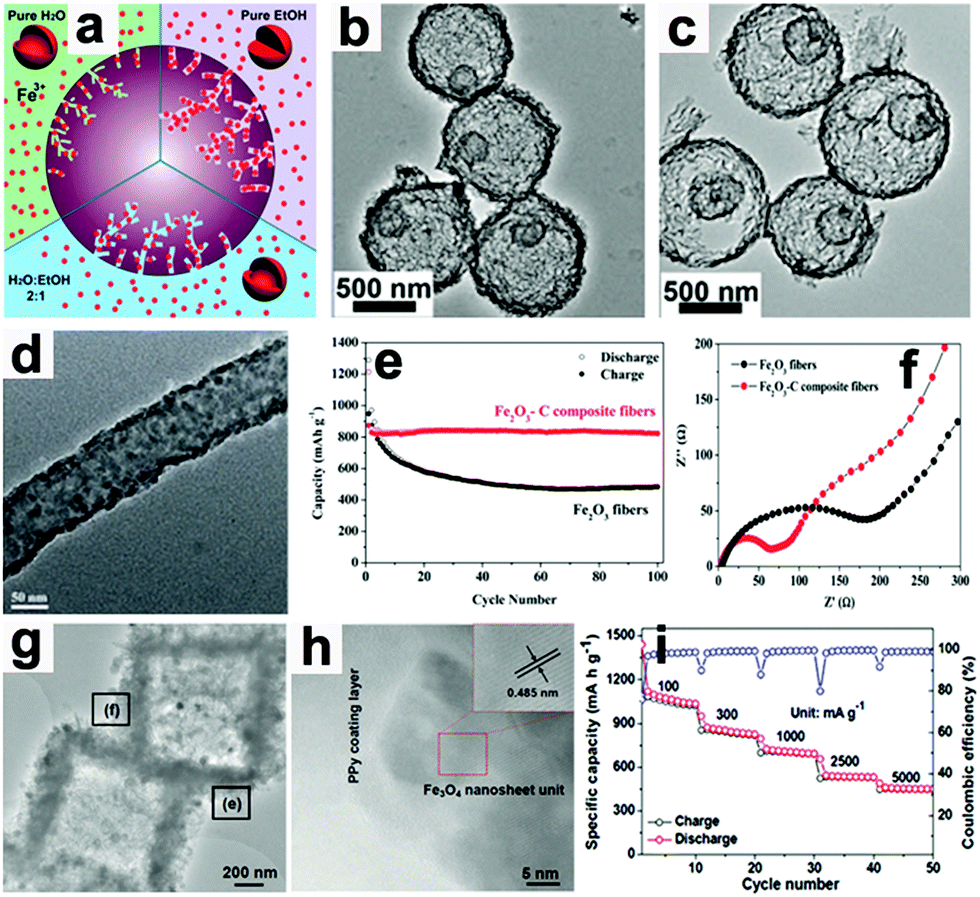 | ||
| Fig. 5 (a) Illustration showing control of the number of multi-shells by adjusting the Fe3+ concentration in carbonaceous microsphere templates. TEM images of thin (b) double-shell and (c) triple-shell Fe2O3 hollow microspheres. Reproduced with permission.53 Copyright 2014, RSC. (d) TEM image of Fe2O3–C composite nanofibers, (e) cycling performance and (f) EIS of Fe2O3–C composite nanofibers and pure Fe2O3 nanofiber electrodes. Reproduced with permission.64 Copyright 2014, RSC. (g) TEM and (h) HR-TEM images of Fe3O4@PPy nanocomposite and its rate capability (i). Reproduced with permission.18 Copyright 2016, Wiley. | ||
When these electrodes are coated with conductive materials, such as carbon and polypyrrole, the conductivity of the electrodes can be enhanced and their rate capabilities can also be improved.18,64,70–73 Lei et al. reported the concept of “confined nanospace pyrolysis” to fabricate coaxial Fe3O4@C hollow particles.70 The obtained coaxial Fe3O4@C hollow particles delivered a high reversible capacity of 864 mA h g−1 after 50 cycles, while hollow Fe3O4 (H-Fe3O4) showed a severely faded capacity of 738.5 mA h g−1 under the same conditions. Moreover, the coaxial Fe3O4@C hollow particles electrode displayed outstanding rate capability compared to its counterparts, especially at high current density (above 1.5 A g−1). Fan's group scattered Fe2O3 nanoparticles in carbon nanofibers by an electrospinning method.64 As presented in Fig. 5d, the Fe2O3 nanoparticles are uniformly distributed in the nanofibers.
The capacity of the obtained Fe2O3–C composite nanofibers electrode was 820 mA h g−1 after 100 cycles, while that of the pure Fe2O3 nanofiber electrode faded rapidly to 482 mA h g−1 (Fig. 5e). As evidenced by electrochemical impedance spectroscopy (EIS, Fig. 5f), the charge-transfer resistance (Rct) of the Fe2O3–C composite nanofibers electrode is much lower than that of the pure Fe2O3 nanofiber electrode, suggesting the importance of the introduction of carbon into the 1D composite nanofibers. Liu et al. constructed a hierarchical Fe3O4@polypyrrole (PPy) nano-cages LIB anode using a template-assisted interfacial reaction followed by in situ polymerization and reduction.18 The TEM images in Fig. 5g and h confirm that the 2D nanosheets are composed of crystalline Fe3O4 and an amorphous PPy component. The obtained electrode demonstrates a high value of 950 mA h g−1 after 100 cycles at 0.2 A g−1 and about 652 mA h g−1 after 500 cycles at 2.0 A g−1 (Fig. 5i). More importantly, this electrode still delivers a reversible capacity of about 490 mA h g−1 at 5.0 A g−1. These studies suggest that cooperation of the conducting material is an effective approach to achieve high rate capability by improving the electron transport in electrodes.
Recently, Paik's group reported an etching-in-a-box strategy to fabricate unique Fe3O4@carbon (Fe3O4@C) yolk–shelled nanocubes.74 This structure not only has the merits of the yolk–shelled hollow structure but also adopts conductive carbon materials as buffer layers, endowing the as-prepared samples with high specific capacity, excellent rate capacity and ultralong cycling stability. They demonstrated that the Fe2O3@PDA core–shelled nanocubes were obtained by coating Fe2O3 with polydopamine (PDA) and were then converted to Fe3O4@C core–shelled nanocubes (Fe3O4@C-0, Fig. 6a) after being annealed. When these as-prepared Fe3O4@C-0 nanocubes were etched with HCl for different times, the Fe3O4 cores were partially etched and a series of yolk–shelled nanocubes with different void space sizes were obtained (Fe3O4@C-1, Fe3O4@C-2, and Fe3O4@C-3 were obtained with etching times of 1, 2, and 3 h, respectively). As depicted in the TEM images in Fig. 6b–d, the sizes of the inner cavities in the Fe3O4@C samples greatly increase as the etching proceeds. The electrochemical performances of these electrodes, shown in Fig. 6e, indicate that an optimized void space is vital for enhanced lithium storage performance. The Fe3O4@C-2 boxes anode could deliver a capacity of 470 mA h g−1 after 8000 cycles at a rate of 10 C (1 C = 1.006 A g−1) with an average coulombic efficiency of around 98% (Fig. 6f). This work suggests that an optimized void space in the electrode material for containing the volume expansion is vital to achieve long cycling stability.
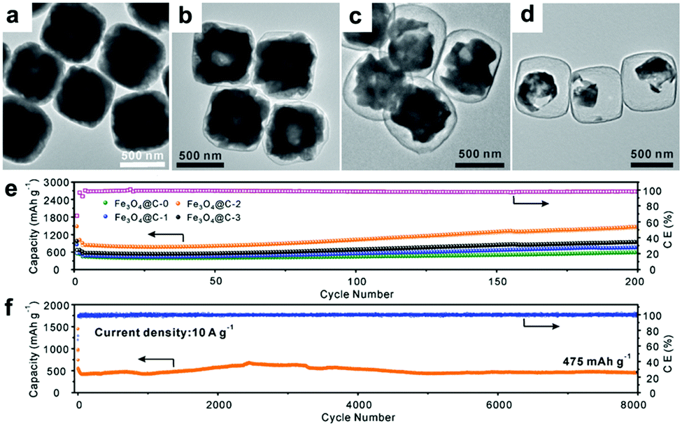 | ||
| Fig. 6 (a–d) TEM images of Fe3O4@C yolk–shelled nanocubes with different etching times (a, 0 h; b, 1 h; c, 2 h; d, 3 h); cycling performance of the four obtained samples at 0.5 A g−1 (e) and the Fe3O4@C-2 yolk–shelled nanocubes at 10 A g−1 (f). Reproduced with permission.74 Copyright 2016, Wiley. | ||
Carbon nanotubes (CNTs) are another important material used in conductive networks for electron transfer.75–78 Jia et al. reported an aerosol spray drying process to construct CNT/Fe3O4 nanocomposites.75 They dispersed as-prepared Fe3O4, CNTs, and sucrose into aqueous solution with the aid of surfactant and used them to generate aerosol droplets. After the annealing process, CNT/Fe3O4 nanocomposites were formed by these aerosol droplets in which CNTs were threaded through the particles and functioned as a conductive network. Thus, excellent rate capability was achieved by this hybrid electrode. Sun et al. prepared carbon-coated FeOx/CNT composites by controlled pyrolysis of ferrocene. The composite electrode achieved an outstanding cycling stability (specific charge capacity retention of up to 84% after 2000 cycles under 2.0 A g−1).76 Cheng's group confined Fe2O3 nanoparticles inside carbon nanotubes and observed the structural evolution during lithium insertion/extraction by in situ TEM.78 Fe2O3 particles with a mean diameter of about 10 nm filling the CNTs were obtained by a wet chemistry technique, and a Fe2O3 nanoparticle-coated CNT sample was also prepared. Taking advantage of in situ TEM, they observed that the nanograins formed inside the CNTs during the electrochemical process were much smaller than those coated on the outside. The cycling performance achieved by the Fe2O3 nanoparticle-filled CNTs was superior to that of Fe2O3 nanoparticle-coated CNTs after aggressive cycling at 7.5 A g−1, suggesting a more stable structure of the former electrode. Moreover, the reasons for the high reversible capacity of the electrodes were discussed in detail. In addition to a capacity of 1007 mA h g−1 contributed by the conversion reaction, enhanced interfacial lithium storage, the reversible reaction of LiOH to form LiH, and partial reversible formation and decomposition of the SEI layer were the vital factors contributing to the high reversible capacity.
In addition to constructing hybrid materials with carbon-based materials, other electrochemically active materials, such as Sn,79 MoS2,80,81 SnO2,82,83 TiO2,84 Co3O4,19 ZnFe2O4,85 CuFe2O4,86 and NiCo2O4,87 are employed to improve the performance of iron oxide anodes. An advantage of these configurations is that there is a synergistic effect between the active components. Zhu et al. reported a three-dimensional MoS2@Fe3O4 nanohybrid.80 In this structure, Fe3O4 particles were uniformly and densely decorated on tubular MoS2. When the MoS2@Fe3O4 was used as an LIB anode, the tubular MoS2 inside it could function as a matrix, offering a hollow interior and mesopores to facilitate Li ion transfer and location and buffer the structure strain during cycling, while the Fe3O4 particulates could serve as a gasket to prevent aggregation of the tubular MoS2. Hence, an encouragingly high reversible capacity of 1113 mA h g−1 was obtained by this electrode, which is much higher than that of the tubular MoS2 anode. Li4Ti5O12 is known for its zero-strain behavior during Li+ intercalation–deintercalation and always shows long cycling stability.88 Kang's group encapsulated Fe3O4 nanoparticles in Li4Ti5O12 nanofibers (NFs) using an electrospinning process combined with subsequent controlled heat treatment to prepare an Fe3O4/Li4Ti5O12 composite. Due to the combination of the stability of Li4Ti5O12 and the high capacity of Fe3O4, the obtained C@Fe–Fe3O4/Li4Ti5O12 hybrid NFs anode exhibited high capacity and long cycle life.20 Rahman et al. reported a breathable structure constructed from clusters of Fe2O3 and SnO2 nanoparticles which were dispersed along carbon black conductive chains.83 The lithiation reactions of these two different materials proceeded at different voltages, which provides breathable aggregation and enables sequential expansion and contraction of the electrode, relieving the problems associated with volume changes. However, agglomeration of the electrode could not be avoided after long cycling because the dimensions of the nanoparticles are not sufficiently small and the mixture is not homogeneous; thus, the electrode exhibited capacity fade after long cycling. Therefore, the mixture electrode showed limited improvement in electrochemical performance compared to single-oxide electrodes.
The relationship between structure and function in hybrid electrodes was studied by Sultana et al.19 Taking a Co3O4−Fe2O3/C system as an example, they demonstrated that the cycling performance and rate capability were improved in the hybrid electrode compared to Co3O4−Fe2O3, Fe2O3/C, and Co3O4/C control electrodes. The results suggested that better management of stress resulting from the sequential reactivity of the components and the enhanced electronic conductivity provided by carbon chains were responsible for the superior electrochemical performance. Jiang et al. reduced the dimensions of the components to 2 to 10 nm and distributed them alternately by pulsed spray evaporation chemical vapor deposition (PSE-CVD).82 In their obtained SnO2–Fe2O3–Li2O film, the 2 to 10 nm nanoparticles with special interfacial relationships had a highly homogeneous distribution. During cycling, the metal oxide nanoparticles were largely locked at their original sites without atom migration. Thus, the structural integrity of the electrode could be well retained, which is critical for stable cycling performance. As a result, the SnO2–Fe2O3–Li2O nanocomposite anode exhibited high volumetric capacity and excellent rate capability. Impressively, a high volumetric capacity of 4704 mA h cm−3 (940.8 mA h g−1) was obtained even when cycled at a current density of 20 A g−1. These studies indicate that conversion reaction electrodes with high electrochemical performance could be fabricated by minimizing the particle size and distributing the composites in a highly homogeneous state.
Fabricating binder-free (integrated) electrodes is another method to improve electrochemical performance, as discussed above.89–96 Luo et al. reported bicontinuous mesoporous Fe3O4 nanostructures on 3D graphene foams and used them as binder-free electrodes.94 They firstly grew graphene on Ni foam by chemical vapor deposition (CVD) and removed the Ni template by etching. Secondly, the remaining 3D graphene foam was coated with a ZnO layer by atomic layer deposition (ALD). Subsequently, the prepared graphene foam was immersed in FeCl3 solution mixed with glucose and then annealed to form bi-continuous mesoporous Fe3O4 nanostructures on graphene foam (GF@Fe3O4). The loading of Fe3O4 could be controlled by adjusting the ZnO layers. This obtained GF@Fe3O4 anode delivered a capacity of 190 mA h g−1 at 60 C (1 C = 1007 mA g−1), demonstrating its excellent rate capability. When their electrode was cycled at rates of 6 C and 10 C up to 500 cycles, the capacity remained at about 400 and 300 mA h g−1, respectively. This outstanding electrochemical performance was ascribed to the well-designed electrode structure. The in situ fabrication method enabled uniform dispersion of the bi-continuous Fe3O4 nanocrystallites on the highly electrically conductive GF, ensuring efficient ion and electron transport and avoiding the aggregation of Fe3O4 particles. Huang et al. designed ordered hierarchically porous 3D electrodes with an entrapped active nanoparticle configuration.95 They tailored the pore size of periodic porous carbon anchored on Ni foam and entrapped Fe2O3 inside the periodic porous carbon. This configuration provided low-resistant avenues for Li ion diffusion and electron transfer and prevented the active nanoparticles from aggregating. Therefore, ultrahigh rate capability and long-term cycling stability were achieved by this binder free electrode (a capacity of 644.71 mA h g−1 after 1300 cycles at 4.0 A g−1). Our group deposited 3D hierarchical Fe2O3 nanosheets on copper foil and evaluated it as a binder-free LIB anode.96 The voids between the nanoparticles which composed the nanosheets and the intervals between the nanosheets offered avenues for Li+ diffusion and provided room for volume changes. Thus, the obtained binder-free electrode delivered long cycling stability and excellent rate capability (a capacity of 817 mA h g−1 was attained at 2.01 A g−1 after 1000 cycles, and a capacity of 433.2 mA h g−1 was obtained at 20.1 A g−1).
2.3. Cobalt oxides
The main phases of cobalt oxides used as LIB anodes are CoO and Co3O4. They react with Li by transferring 2 and 8 electrons per mole of material and deliver theoretical specific capacities of 715 and 890 mA h g−1, respectively. In contrast to the well-accepted mechanism of the reaction of CoO with Li,97–99| CoO + 2Li+ + 2e− ↔ Co + Li2O | (15) |
| Co3O4 + 8Li+ + 8e− ↔ 3Co + 4Li2O | (16) |
Meanwhile, the other view is that this reaction is not fully reversible and that the lithiation product Co nanograins should be reoxidated to CoO, not Co3O4.105,106 Su et al. directly observed the dynamic structure changes of porous Co3O4 nanoplates/graphene in LIBs by in TEM.106 They found that the highly crystalline Co3O4 nanoplates transformed into numerous Co nanograins and Li2O during the first lithiation (eqn (17)). The following electrochemical reaction was a reversible conversion between Co nanograins and CoO nanograins (eqn (18)), not conversion between Co and Co3O4. The irreversible phase conversion of Co3O4 in the first cycle is responsible for the initial capacity fading. The whole reaction can be expressed as follows:
| Co3O4 + 8Li+ + 8e− → 3Co + 4Li2O (first lithiation) | (17) |
| Co + Li2O ↔ CoO + 2Li+ + 2e− | (18) |
In addition to the debate over the reaction mechanisms, volume changes and low conductivity are also drawbacks of these materials. Constructing hollow structures or multi-shelled hollow nanostructures organized by secondary subunits is considered to be an effective method to release the strain caused by volume changes.21,107–110 Wang's group controlled the shell numbers of Co3O4 hollow microspheres accurately by adjusting the size and diffusion rate of the hydrated Co2+ as well as the absorption capability of the carbonaceous microspheres (CMSs).107 As shown in Fig. 7a, single-shelled Co3O4 microspheres were finally obtained when water alone was used as the solvent. When the amount of ethanol in the aqueous solution was increased, the size of the hydrated Co2+ in the solution decreased owing to the lower coordination of H2O and the increased diffusion rate of hydrated Co2+ in the CMS templates. As a result, double-shelled Co3O4 microspheres were formed when the CMCs were removed (Fig. 7b and e). When the diffusion rate of hydrated Co2+ was further accelerated by increasing the amount of ethanol up to 75% by volume and heating the solutions at higher temperatures, triple-shelled Co3O4 was obtained (Fig. 7c and f). Additionally, enlargement of the surface area and pore volume of the CMCs template by HCl treatment could enable more Co2+ to penetrate, achieving the formation of quadruple-shelled Co3O4 (Fig. 7d and g). In virtue of the multishell hollow structure, the prepared Co3O4 hollow microspheres delivered higher capacity than commercial Co3O4; the triple-shelled Co3O4 microspheres showed the highest specific capacity and best cycling performance, as shown in Fig. 7h.
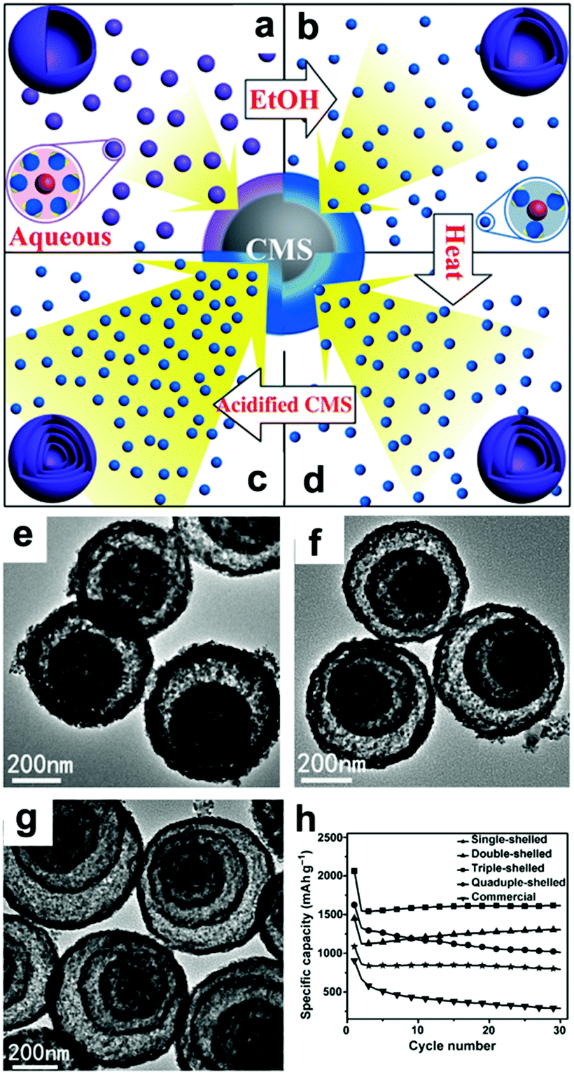 | ||
| Fig. 7 Mechanism for the controlled formation of multishelled Co3O4 hollow microspheres (a–d); (e–g) TEM images and (h) cycling performance of double-, triple-, and quadruple-shelled Co3O4 hollow microspheres. Reproduced with permission.107 Copyright 2014, Wiley. | ||
A 3D interconnected carbon-based network is an ideal structure to enhance the conductivity of a hybrid material and release the stress of volume changes.97,111–114 Yao et al. developed a one-step multipurpose strategy to hybridize flexible graphene nanosheets with Co3O4 nanowires.111 The resulting mesoporous Co3O4 nanowires confined by N-doped graphene aerogel anode feature enhanced electrochemical properties, delivering a high capacity of more than 1200 mA h g−1 after 200 cycles. Self-adhesive Co3O4/expanded graphite paper115 and Co3O4 nanoparticles-embedded carbonaceous fibers112,113 have been fabricated, and all these electrodes exhibited excellent electrochemical performance.
Metal–organic frameworks (MOFs), assembled from two main parts of inorganic vertices (metal ions or clusters) and organic linkers, are noted for their high surface areas and well-designed pore structures.116 This class of porous material has been demonstrated to provide promising templates or precursors to produce novel porous transition metal oxide nanostructures. The porous structure is beneficial for reducing the Li+ diffusion distance and relieving volume expansion strain. Moreover, the carbon matrix can be derived from the organic linkers under well-controlled conditions, which is important to enhance the electronic conductivity of the electrode material. Hou et al. prepared Co-based zeolitic imidazolate frameworks (ZIF-67) at room temperature and used them as precursors to obtain Co3O4/N-doped porous carbon dodecahedrons.117 In the obtained hybrid dodecahedrons, Co3O4 nanoparticles with dimensions of 15 to 30 nm were embedded in the N-doped porous carbon network which was derived from the organic linkers. The mean pore size and the specific surface area were calculated to be 36 nm and 97 m2 g−1, suggesting its mesoporous architecture. The unique rational structure that utilized the synergic merits of the highly conductive porous carbon matrix and well-defined Co3O4 nanoparticles could accommodate volume expansion and improve the electric and ionic conductivity, endowing the hybrid material with long cycling stability and excellent rate capability.
Wang's group inserted MWCNTs in MOFs to construct hierarchical porous MWCNTs/Co3O4 nanocomposites.103 Carboxylic group (–COOH)-functionalized MWCNTs were used to adsorb Co2+ and served as nucleation centers for loading MOFs in 2-methylimidazolate methanol solution. As a result, the MWCNTs were self-inserted in situ into the ZIF-67 (Co) crystals.
Finally, MWCNTs/Co3O4 was obtained from MWCNTs/ZIF-67 by conducting heat treatment at 400 °C in air. The designed MWCNTs/Co3O4 integrated the excellent conductivity and strong mechanical/chemical stability of MWCNTs and the high theoretical capacity of Co3O4, displaying capacities of 813 mA h g−1 at 0.1 A g−1 and 541 mA h g−1 at 1.0 A g−1. Furthermore, their protocol could be further extended to the construction of MWCNTs/ZnCo2O4 polyhedrons using MWCNTs/ZIF-67 (Zn, Co) as a precursor. Recently, our group prepared hierarchical porous ZnO/ZnCo2O4 nanosheets using a Zn–Co-MOF nanosheets precursor.118 Qu et al. spread ZIF-67 on graphene oxide nanosheets and used them as precursors to obtain ultrafine Co3O4 nanocrystallites (<10 nm) grown on graphene.119 The obtained graphene/Co3O4 manifested long-term cycling stability and excellent rate behavior (a capacity of 877 mA h g−1 at 5 A g−1).
Lou's group designed hierarchical tubular structures composed of in situ-formed CNTs and Co3O4 hollow nanoparticles to address multiple issues at the same time.120Fig. 8a illustrates the innovative fabrication of the hierarchical CNT/Co3O4 microtubes. They first prepared polyacrylonitrile (PAN)–cobalt acetate (Co(Ac)2) composite nanofibers (PAN–Co(Ac)2) and used them as the template and cobalt source for the growth of ZIF-67 nanotubes. After dissolving the extra PAN–Co(Ac)2 core and annealing in Ar/H2, the ZIF-67 tubular structures transformed into CNT/Co–carbon hybrids. Finally, hierarchical CNT/Co3O4 microtubes were obtained after the CNT/Co–carbon hybrids underwent controlled thermal annealing in air. As confirmed by the SEM and TEM images in Fig. 8b–d, the ZIF-67 tubular structures were totally converted to hierarchical CNT/Co3O4 microtubes, in which the sizes of the Co3O4 hollow nanoparticles ranged from 15 to 30 nm and the inner diameter of the CNTs was about 3 ± 2 nm. As a consequence, the hierarchical structure showed a high specific surface area of 93.9 m2 g−1 and small pore sizes (mostly below 15 nm). This configuration not only provides a short Li+ diffusion distance but also offers sufficient contact area for the charge-transfer reaction. Furthermore, the hollow structure could relieve volume expansion stress, and the CNTs integrated in the hierarchical tubular structures improved the electronic conductivity of the hybrid material. Consequently, their CNT/Co3O4 LIBs anode delivered a high reversible capacity of 1281 mA h g−1 at 0.1 A g−1 with a high rate capability and long cycle life over 200 cycles.
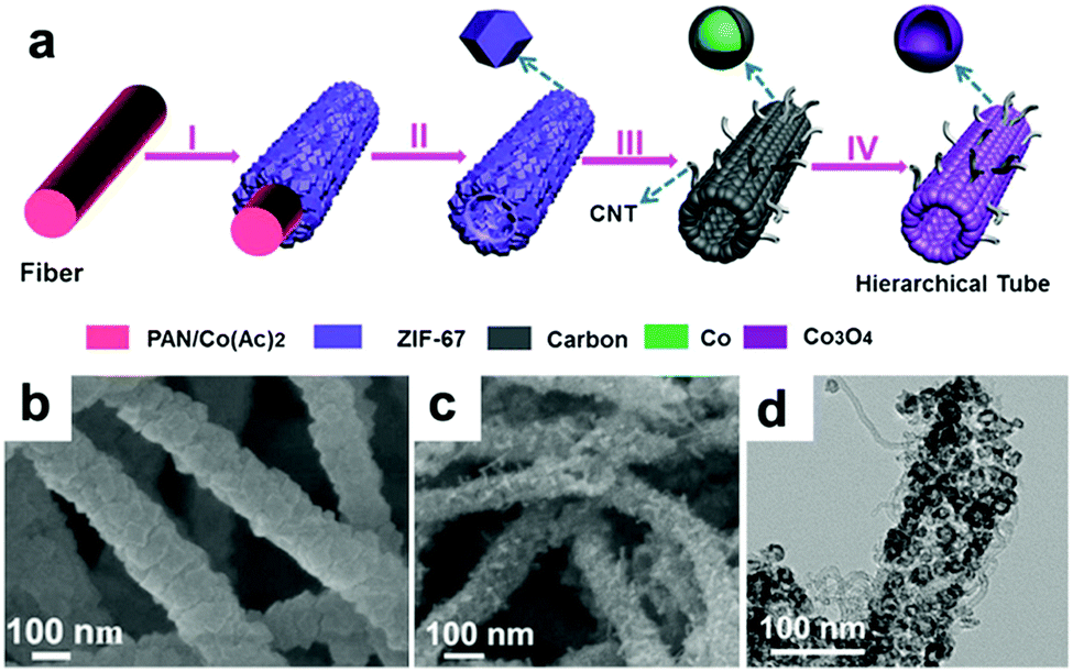 | ||
| Fig. 8 (a) Formation of hierarchical CNT/Co3O4 microtubes. (b) SEM image of the as-prepared ZIF-67 microtubes. SEM (c) and TEM (d) images of the as-prepared CNT/Co3O4 microtubes. Reproduced with permission.120 Copyright 2016, Wiley. | ||
The electrodes mentioned above were prepared by a traditional slurry coating method, in which insulating binders are required to adhere the active materials to the current collector. The addition of binders not only may block the active sites but also decrease the electronic conductivity of the electrodes, impeding efforts to enhance the conductivity of the hybrid materials. Therefore, the rational fabrication of binder-free electrodes with various morphologies is meaningful. Zhang's group reported a novel strategy to fabricate binder-free CoO/graphene electrodes using an intelligent electrostatically induced spread growth method.114 As they pointed out, the as-prepared α-Co(OH)2 nanosheets (Fig. 9a) are positively charged and the graphene oxide is negatively charged; therefore, mutual electrostatic interactions between these two materials can drive the assembly. Moreover, a large amount of ultrathin α-Co(OH)2 nanosheets can be absorbed owing to the high surface area of GO. When the composites undergo reflux reactions under reduction atmosphere, α-Co(OH)2 nanosheets are transformed to β-Co(OH)2 and GO is reduced to graphene. The β-Co(OH)2 nanosheets grow with the graphene surface at the same time and finally uniformly disperse on the graphene (Fig. 9b). Finally, a binder-free CoO/graphene anode (Fig. 9c) is constructed on Cu foil after the process of drop-coating, drying, and sintering of the β-Co(OH)2 nanosheets and graphene composites. The capacity of the obtained binder-free CoO/graphene anode after 5000 cycles at a current density of 1.0 A g−1 is 604 mA h g−1, showing a high reversible capacity and outstanding cycling stability. As a comparison, the electrode with PVDF exhibits inferior cycling stability and lower specific capacity. The superior electrochemical performance of the binder-free electrode should be ascribed to its rationally designed structure. The thin CoO nanosheets can shorten the Li+ ion diffusion pathways, the encompassment of highly conductive graphene can ensure fast electron transfer, and the absence of insulating PVDF binder can maintain the high electronic conductivity of the electrode.
 | ||
| Fig. 9 TEM images of α-Co(OH)2 nanosheets (a) and β-Co(OH)2 nanosheets/graphene hybrid (b); image of the CoO/graphene hybrid (c). Reproduced with permission.114 Copyright 2013, Wiley. (d) TEM image of the Co3O4/carbon nanosheet array. Reproduced with permission.121 Copyright 2015, RSC. SEM (e) and TEM (f) images of CoO nanowire clusters. Reproduced with permission.99 Copyright 2015, Wiley. (g) SEM image of Co3O4/3DNF. Reproduced with permission.122 Copyright 2016, Elsevier. | ||
Hollow Co3O4 nanoparticles confined in thin carbon nanosheet arrays were fabricated on Ni foam and used as a binder-free electrode for LIBs by Peng et al.121 Co(OH)2 nanosheet arrays were firstly electrodeposited on Ni foam; then, carbon layers were coated by a hydrothermal reaction using glucose as a green carbon source. Upon being annealed in H2 and air atmosphere in sequence, hollow Co3O4 nanoparticles about 10 to 20 nm in size were formed due to the nanoscale Kirkendall effect and uniformly distributed in the thin carbon nanosheets (Fig. 9d). The as-prepared binder free anode features intimate contact between the active material and Ni foam current collector, high surface area, and an open framework, which are vital to achieve excellent electrochemical performance. CoO nanowire clusters grown on Cu foil were fabricated by our group and evaluated as a binder-free LIB anode.99Fig. 9e and f suggest that the CoO nanowires are composed of small nanoparticles about 10 nm in size that are directly grown on the current collectors. More importantly, the voids between the nanoparticles and the spaces between the nanowires are helpful for electrolyte permeation as well as remission of stress caused by volume changes. Additionally, the small particles shorten the Li+ diffusion distances in the materials. As a consequence, the obtained electrode exhibits a high reversible capacity of 1516.2 mA h g−1 at 1 C (1 C = 0.716 A g−1), which is higher than the theoretical specific capacity. We discussed the origins of the additional capacity, and our results suggested that the higher-oxidation-state products and pseudocapacitive charges should be responsible for this phenomenon. Moreover, we fabricated nano-reactors for the CoO nanowires by coating them with amorphous silica shells. The shell worked as a stiff scaffold to prevent outward volume expansion, preserving the morphology of the nanowires and enhancing the cycling stability of the binder free electrodes. Fang et al. coated MOFs on 3D current collectors and used them as a precursor to prepare porous transition metal oxide binder-free electrodes.122 As a proof of concept, a Co3O4/3D nickel foam (Co3O4/3DNF) hybrid binder-free electrode was obtained (Fig. 9g). This electrode possesses the advantages of porous nanostructures and a 3D conductive substrate.
2.4. Nickel oxide
Nickel oxide (NiO) has received a great deal of attention due to its high theoretical capacity (718 mA h g−1) and high volumetric density (6.67 g cm−3). However, the practical application of NiO in LIBs is still hindered by its poor cycling stability and very poor rate capability, which result from its intrinsically low conductivity and drastic volume variations during the continuous discharge/charge process. There are three main effective strategies to overcome these obstacles. The first significant approach is to construct nanostructured NiO, such as nanofibers,123 nanosheets,124,125 nanoparticles,126 nanoflowers,127,128 nanorods,129 nanowires,130 hierarchical microspheres,131 and multi-shelled hollow microspheres.132NiO with nanoscale structures efficiently shortens the length of Li+ diffusion and has improved structural stability and enhanced electrode/electrolyte surface contact area, contributing to enhanced electrochemical performance. For example, Bell et al. fabricated free-standing Ni–NiO nanofibers with a core–shell structure by a feasible process of electrospinning and thermal oxidation.123 In Fig. 10a, it can be seen that the Ni–NiO nanofibers are continuous while the surface is rough, which is due to NiO layers attaching on the surface of the Ni nanofibers. When tested as an anode in LIBs, the Ni–NiO nanofibers demonstrated extraordinary performance, with a capacity of 1054 mA h g−1 at 3 C (1 C = 718 mA g−1), an ultralong cycle life of more than 1500 cycles, and excellent stability, with a coulombic efficiency of up to 99%. Additionally, ultrathin NiO nanosheets (4 to 5 nm in thickness) have been synthesized by Sun et al.124 The TEM image of the ultrathin NiO nanosheets displayed in Fig. 10b clearly suggests their nanosheet-like structures. When evaluated as a LIB anode, the NiO nanosheets manifested high reversible capacities of 1242 and 250 mA h g−1 at 0.2 and 15 A g−1, respectively. Furthermore, 3D binder-free NiO nanorod-anchored Ni foam electrodes were fabricated by Yang et al.129 Due to its favorable morphology and the abundant electrical contact between NiO and Ni foam, the obtained binder-free electrode exhibits high reversible capacity and superior rate performance. The second vital method is to fabricate novel composites combining NiO with conductive materials. Among these, graphene,133 amorphous carbon,134 MWCNTs,135 metal,136,137 and amorphous carbon nanotubes138 are all excellent options. Lou's group constructed hybrid bowl-like structures by anchoring NiO nanosheets on flat carbon hollow particles.139 The SEM and TEM images presented in Fig. 10c specifically indicate the hollow structure of this bowl-like NiO/C hybrid. This unique structure combines the merits of NiO sheet-like nano-building blocks and carbon layers, which effectively enhances the conductivity of the electrode and inhibits self-agglomeration of the active materials. Consequently, high specific capacity (1012 mA h g−1 at 0.2 A g−1), good cycling stability (93.8% capacity retention after 150 cycles at 0.2 A g−1) and superior rate performance (608 mA h g−1 at 1.6 A g−1) were achieved. Shan et al. prepared NiO/graphene via a hydrothermal method and visualized the role of graphene during lithiation by in situ TEM.133 Their results suggest that the addition of graphene enhances Li+ diffusion kinetics by increasing the Li+ diffusion rate, limits the expansion of NiO, and retains the tight electrical contact between NiO and graphene. Feng et al.134 reported 2D sandwich-like NiO/C arrays on Ti foil through a hydrothermal method (Fig. 10d). The obtained sandwiched composites possess numerous active sites as well as enhanced contact area between the electrolyte and active materials. Furthermore, this configuration also protects the active nanoparticles from peeling off from the conductive substrate, ensuring excellent electrochemical performance (a capacity of ∼1458 mA h g−1 at 0.5 A g−1 was obtained, and a capacity of ∼95.7% was retained after 300 cycles) of this electrode. Susantyoko et al. sputtered NiO on vertically-aligned MWCNT arrays as an LIBs anode (MWCNT/NiO),135 of which MWCNT/NiO presents a specific capacity of 864.8 mA h g−1 at 143.6 mA g−1 after 50 cycles. In addition, fabricating sophisticated and unique structures is a powerful method to improve the electrochemical performance of NiO. For example, a hierarchical hollow ball-in-ball NiO/Ni/graphene architecture (Fig. 10e) has been reported by Zou et al.140 A high reversible specific capacity, excellent rate capability, and ultralong cycling stability are achieved when this architecture is evaluated as an LIB anode (Fig. 10f). This extraordinary performance benefits from the well-designed, unique structure of the NiO/Ni/graphene composites, which mitigates the volume changes of NiO and offers a continuous, highly conductive matrix to facilitate fast electron transfer and form stable SEI layers. Furthermore, “curved” NiO nanomembranes have been reported through a simple fabrication technique followed by a thermal treatment process by Sun et al.141 The “curved” structure was confirmed by the SEM image in Fig. 10g. The CV curves in Fig. 10h present an intense peak located at around 0.5 V in the cathodic scan during the first cycle, corresponding to the reduction of NiO to Ni, as well as the formation of SEI layers. Afterwards, this cathodic peak shifts to about 1.07 V and becomes weaker. The two broad anodic peaks located at about 1.4 and 2.2 V can be attributed to the decomposition of the SEI layer and the oxidation of Ni nanoparticles to NiO, respectively. The curved NiO nanomembranes deliver a high capacity of 721 mA h g−1 at 1.5 C, an ultrafast power rate (50 C), and a long lifetime (1400 cycles) when evaluated as a LIB anode.
 | ||
| Fig. 10 (a) SEM image of core–shell nanofibers of NiO prepared by electrospinning. Reproduced with permission.123 Copyright 2015, Elsevier. (b) TEM image and inset in (b) SAED patterns of NiO nanosheets. Reproduced with permission.124 Copyright 2015, Elsevier. (c) SEM and TEM images (inset of c) of hybrid bowl-like structures obtained by anchoring NiO nanosheets on flat carbon hollow particles. Reproduced with permission.139 Copyright 2015, RSC. (d) SEM image of 2D sandwich-like NiO/C arrays. Reproduced with permission.134 Copyright 2016, Elsevier. (e) TEM images and (f) rate performance of hierarchical hollow ball-in-ball NiO/Ni/graphene nanostructured materials. Reproduced with permission.140 Copyright 2016, ACS. (g) SEM image, (h) cyclic voltammetry curves of the curved NiO nanomembranes. Reproduced with permission.141 Copyright 2014, Wiley. | ||
2.5. Copper oxide
When used as a LIB anode, CuO forms Cu metal nanoparticles embedded in an Li2O matrix during the discharge process and re-forms as CuO during the charge process. CuO electrodes suffer from large volume expansion (174%), low conductivity (p-type semiconductor), and subsequent particle pulverization, resulting in rapid capacity fading and poor cycling performance. In order to efficiently address these issues, one effective way is to construct micro-/nano-structured CuO materials with various morphologies, mainly including nanowires (Fig. 11a),142–144 nanosheets (Fig. 11b),145 nanofibers (Fig. 11c),146 nanorods,147 nanoribbons,148,149 3D hierarchical mesocrystals (Fig. 11d),150 and hollow structures (Fig. 11e and f).151,152 The nanostructured CuO can alleviate mechanical strain and reduce the diffusion length of Li+, leading to excellent performance for Li storage. For example, Zhang et al.144 have fabricated vertically aligned single crystalline CuO nanowires on nickel foam by one-step thermal oxidation. The growth mechanism of CuO nanowires is regarded as stress-driven grain-boundary diffusion associated with surface diffusion of Cu atoms/ions. When used as a binder-free LIB anode, the CuO nanowires exhibit a high capacity of 692 mA h g−1 after 50 cycles at 0.1 A g−1 and a reversible capacity of up to 445 mA h g−1 over 600 cycles, even at 1.0 A g−1.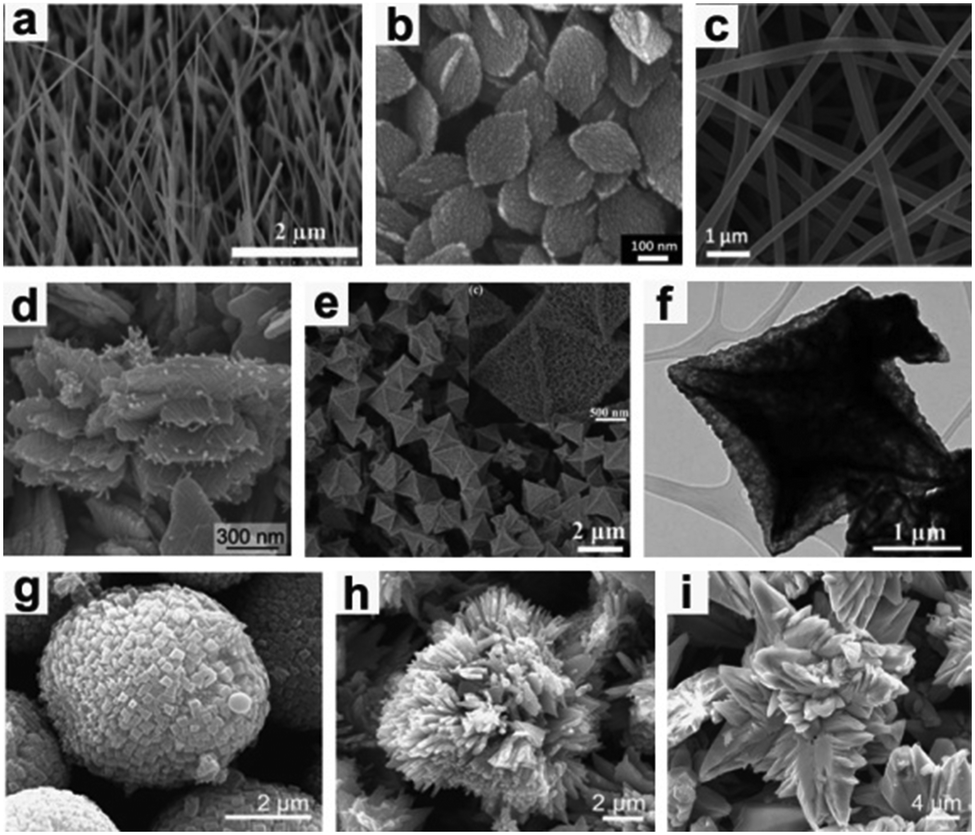 | ||
| Fig. 11 (a) Nanowires, reproduced with permission.144 Copyright 2014, RSC. (b) Nanosheets, reproduced with permission.145 Copyright 2013, RSC. (c) Nanofibers, reproduced with permission.146 Copyright 2016, RSC. (d) 3D hierarchical mesocrystals, reproduced with permission.150 Copyright 2016, RSC. (e and f) Hollow structures, reproduced with permission.152 Copyright 2013, RSC. (g) Microspherical, (h) flower-like and (i) thorn-like CuO structures. Reproduced with permission.153 Copyright 2014, Elsevier. | ||
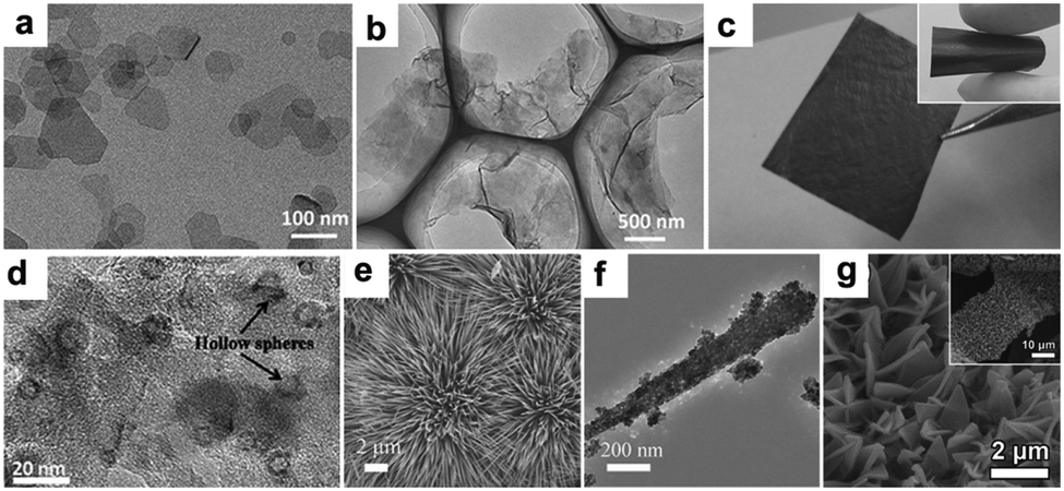
Furthermore, CuO nanowires coated with graphene quantum dots (GQD) grown on Cu foam have been designed and synthesized by Fan's group.143 The unique GQD soft protection greatly increases the surface conductivity and stability of the nanowire arrays. Consequently, when the CuO–Cu–GQD triaxial nanowire arrays were applied to the LIB anode, they deliver a high reversible capacity (780 mA h g−1 at 1/3 C), a superior rate capability (330 mA h g−1 at 30 C) and excellent long-term cycling stability (almost no capacity decay after 1000 cycles). In addition, Wang et al.153 controllably synthesized three types of micro/nanostructured CuO (CuO microspheres, flower-like CuO and thorn-like CuO) anodes for lithium-ion batteries (Fig. 11g–i). The CuO microspheres anode demonstrates much better electrochemical performance than the other two CuO samples in terms of cycling performance and rate capability. Another ideal strategy is to construct smart hybrid architectures by integrating CuO with conductive matrixes (such as carbon matrix,154–158 metal159 and other conductive substances160), which not only improve the conductivity of CuO but also restrain the self-aggregation of CuO active materials during the cycling process. Liu's group encapsulated CuO nanoparticles in mesoporous carbon multi-yolk–shell octahedra through a solvothermal process followed by thermal treatment (Fig. 12a).154 In the obtained samples, the multiple CuO nanoparticles are well-embedded in the compartments of octahedral carbon scaffolds. This novel multi-yolk–shell structure can effectively buffer volume variations, prevent the aggregation of CuO nanoparticles during the charge/discharge process and stabilize the SEI layers. Therefore, the CuO@C octahedra anode demonstrates high reversible capacity (598 mA h g−1 at 0.25 A g−1), excellent rate capacity and long-term cycling stability in LIBs. In addition, Ko et al. reported CuO/MWCNTs nanocomposites in which mesoporous CuO particles are threaded by MWCNTs in the long-axis direction. 158 The high porosity of the CuO particles allows easy access of Li ions and acts as an elastic to buffer volume variations during the lithiation/delithiation process. The electrodes achieved remarkably improved electrochemical performance because the MWCNTs efficiently enhanced the electronic conductivity of the nanocomposites. Wang's group155 fabricated carbon-coated CuO hollow spheres via a feasible aerosol spray pyrolysis method. In the hollow structure, a thin layer of CuO nanoparticles in the inner chamber was anchored to the carbon shell. The hollow spherical particles anode exhibited a high capacity (670 mA h g−1 at 1 C) as well as outstanding rate capacity (a capacity of 400 mA h g−1 at 50 C was retained after 300 cycles). The extraordinary electrochemical performance resulted from the structure of the carbon-coated hollow spheres. This unique structure improves the electronic conductivity of the hybrid material, decreases the diffusion distance of Li ions, and provides sufficient space for the volume expansion of CuO particles during the discharge/charge process.
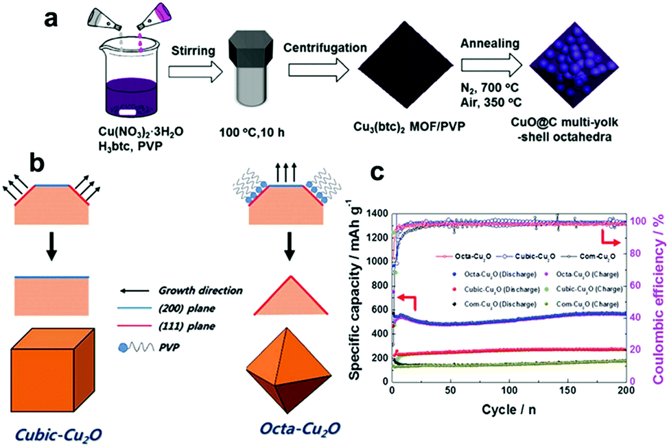 | ||
| Fig. 12 (a) The synthesis procedure of CuO-encapsulated mesoporous carbon multi-yolk–shell octahedra. Reproduced with permission.154 Copyright 2016, Elsevier. (b) The formation mechanisms of cubic-Cu2O and octa-Cu2O. (c) Comparison of the cycling performances of cubic Cu2O, octahedral Cu2O and commercial Cu2O. Reproduced with permission.164 Copyright 2015, RSC. | ||
In addition to CuO, Cu2O has also aroused the interest of researchers as a LIB anode material due to its high reversible reaction with Li+, non-toxicity, and low cost. Unfortunately, inferior capacity and stability resulting from extreme volume expansion during the process of delithiation/lithiation have hindered the development of Cu2O. Recently, many researchers have focused on fabricating nanostructured Cu2O electrodes with controlled shapes, mainly including nanorod arrays,161,162 porous hollow nanospheres,163 and cubic Cu2O,164,165 for improving the performance of Cu2O anodes. Cubic and octahedral Cu2O nanostructures have been prepared by Kim et al.164Fig. 12b schematically illustrates the formation mechanisms of cubic and octahedral Cu2O. In the presence of PVP, the sample tends to form octahedral Cu2O with dominant (111) facets because PVP mainly adsorbs on the (111) plane. In contrast, the sample tends to form cubic Cu2O with more thermodynamically stable (100) facets in the absence of PVP. Hence, it is found that cubic Cu2O and octahedral Cu2O have dominant (100) and (111) facets, respectively. The electrochemical performance of octahedral Cu2O is superior to that of cubic Cu2O (Fig. 12c), regardless of the achieved specific capacity or the rate capability; this may be because a crystal structure consisting of (111) facets facilitates lithium ion transport, as the authors declared.164
2.6. Ruthenium oxide
Ruthenium dioxide, RuO2, features a tetragonal rutile structure and metallic-type electronic conduction (σ is about 103 to 104 S cm−1 at 300 K). As a precious metal, RuO2 is not a desirable candidate as a LIB anode material. It is often chosen as a prototype material to study the conversion reaction mechanism due to its high coulombic efficiency and good mass transport properties.166–171 More importantly, it does not form superparamagnetic nanoparticles like Fe and Co systems, which enables the application of many techniques. Theoretically, RuO2 can accept four electrons per formula unit when used as an LIB anode material, delivering a theoretical capacity of 806 mA h g−1. As with other conversion reaction materials, the measured capacity is always larger than the theoretical capacity. Grey's group chose RuO2 as a prototype material to investigate the origin of this additional capacity.169 They employed X-ray absorption spectroscopy (XAS), in situ pair distribution function methods, high-resolution multinuclear/multidimensional solid-state NMR techniques, and other electrochemical measurements to identify the origins of the additional capacity. As they summarized, the formation of LiOH and the subsequent reversible formation of Li2O and LiH were confirmed as the main origins of the additional capacity in their system. Additionally, the reversible formation of SEI layers and Li adsorption also contribute to the additional capacity. Kim et al. investigated the structural changes and electrochemical behavior of RuO2 by in situ XRD and X-ray absorption spectroscopy combined with electrochemical techniques.170 They found that intermediate phase LiRuO2 was initially formed at the start of discharge and further decomposed to Ru metal and Li2O by a conversion reaction. They also probed the source of the additional capacity by TEM, X-ray photoelectron spectroscopy, and the galvanostatic intermittent titration technique. They proposed that the additional capacity results from Li storage in the grain boundary between the Ru nanoparticles and Li2O.2.7. Chromium oxide
Cr2O3 has been evaluated as LIB anode due to its high theoretical capacity of 1058 mA h g−1 and relatively low lithium insertion potential of 1.08 V. However, Cr2O3 has the drawbacks of very poor electronic conductivity and severe volume variation during the cycling process, which result in rapid deterioration of cyclic performance. To address these issues, many strategies, mainly including the fabrication of micro-/nano-structured materials and hybrid composites such as mesoporous Cr2O3,172,173 Cr2O3/graphene,174,175 Cr2O3/CNTs,176 and carbon-coated graphene–Cr2O3,177 have been reported. Liu et al. constructed highly ordered mesoporous Cr2O3 materials by a vacuum-assisted route using 2-dimensional (2D) hexagonal SBA-15 and 3D cubic KIT-6 silica as templates.172Fig. 13a and b present TEM images of 2D hexagonal Cr2O3 (denoted as H-Cr2O3), from which we can observe that H-Cr2O3 is dominated by a wire-like array shape. Additionally, Fig. 13c and d clearly indicate that C-Cr2O3 possesses large scales of irregular spherical particles with highly ordered mesopores. Owing to the high surface area, thin crystal walls, and narrow pore size distribution on these unique ordered mesoporous materials (Fig. 13e), the mesoporous H-Cr2O3 and C-Cr2O3 electrodes demonstrate enhanced discharge capacities of 521 mA h g−1 and 540 mA h g−1 after 100 cycles compared to a bulk Cr2O3 (B-Cr2O3) electrode (Fig. 13f). In addition, the intercalation-transformation method has been developed to fabricate sandwich-like Cr2O3–graphite intercalation composites (Cr2O3–GICs).178 The resulting Cr2O3–GICs manifests a reversible capacity as high as 500 mA h g−1 and extremely stable cycling performance with over 100% capacity retention after 1000 cycles. | ||
| Fig. 13 (a) TEM and (b) HRTEM images of H-Cr2O3. (c) TEM and (d) HRTEM images of C-Cr2O3. (e) Nitrogen sorption isotherms and inset in (e) corresponding pore size distribution. (f) Cycle performance of B-Cr2O3, H-Cr2O3 and C-Cr2O3. Reproduced with permission.172 Copyright 2012, RSC. | ||
2.8. Molybdenum oxide
It is well known that MoO3 exists in three different forms: orthorhombic (α-MoO3), monoclinic (β-MoO3), and hexagonal (h-MoO3). α-MoO3 is the most stable phase; its anisotropic layered structure makes it a suitable candidate for LIBs. Based on the conversion reaction mechanism, a high theoretical specific capacity of 1117 mA h g−1 is delivered by MoO3 anodes. However, poor conductivity and tremendous volumetric variations during the discharge/charge process lead to very poor cyclic stability and rapid capacity fading. Similar to other transition metal oxides, numerous efforts have been devoted to constructing nanostructured MoO3, such as nanorods,179 nanobelts,180 and nanowires.181 Qian's group prepared mesoporous orthorhombic MoO3 nanowire bundles from single-crystal α-MoO3·H2O nanorods via a feasible method of vacuum topotactic transformation.181 The as-prepared MoO3 nanowire bundles exhibited a high reversible capacity of 954.8 mA h g−1 after 150 cycles when tested as a LIB anode. Another efficient method to improve the cycling stability and rate performance of MoO3 anode materials is the construction of self-supported nanostructure materials directly on current collectors. Additionally, coating a conductive layer and confining the MoO3 active material in a selected matrix are regarded as effective strategies to improve the conductivity and relieve the structure degradation of MoO3.181–189 For example, an anion-exchange reaction has been developed to fabricate a tailored heterostructure of MoO3@MoS2 (MoS2 nanosheets grown on MoO3 nanowires) by Liu et al.182 Due to the abundant Li+ diffusion channels resulting from layered MoS2 nanosheets grown on MoO3 nanowires and the synergistic effect between the MoO3 nanowires and MoS2 nanosheets, MoO3@MoS2 exhibits a high discharge capacity (1510 mA h g−1 was obtained at 0.1 A g−1) and good cycle performance (a discharge capacity of 781 mA h g−1 was retained after 100 cycles). More interestingly, many complicated and subtle structures of MoO3 have been proposed in recent years.190,191 Kang's group reported a new MoO3 structure, named “ant-cave-microball” by spraying pyrolysis using a colloidal spray solution with polystyrene nanobeads, molybdenum salt, and sucrose.191 As depicted in the SEM image in Fig. 14a, the “ant-cave-structured” MoO3-C microballs possess many open nanochannels which are uniformly distributed inside the microballs. Meanwhile, the MoO3 and carbon components are distributed homogeneously in the microballs. As illustrated in Fig. 14b, the channels facilitate electrolyte immersion and shorten the Li+ diffusion distance. Moreover, the carbon component can improve the electronic conductivity of the microballs and function as a buffering layer for volume changes during the lithiation and delithiation processes. Owing to the synergistic effect of the nanochannels and carbon components of this unique structure, an “ant-cave-structured” MoO3-C microball anode delivered superior cycling performance (a capacity of 733 mA h g−1 after 300 cycles) and high rate performance (a capacity of 679 mA h g−1 even at 3 A g−1). Li et al.192 systematically investigated the lithium adsorption and diffusion behavior in MoO3 with different dimensions by density functional theory computations. Their computational results suggest that MoO3 monolayer nanosheets and nanoribbons have more attractive properties, such as fast Li+ diffusion, high operating voltage, excellent electronic conductivity, and large energy density. Due to these properties, MoO3 nanosheets and nanoribbons have become promising high-rate LIB anodes. | ||
| Fig. 14 (a) SEM image of ant-cave-structured MoO3-C. (b) Illustration of electrolyte penetration in ant-cave-structured MoO3-C composite powders. Reproduced with permission.191 Copyright 2013, ACS. (c) The sequential self-templating mechanism for formation of triple-shelled Mo-PDA hollow spheres. Reproduced with permission.202 Copyright 2016, Wiley. | ||
Among molybdenum-based oxides, MoO2 has also received substantial attention. Diverse MoO2 nanomaterials, such as nanotubes,193 nanorods,194 nanobelts,195 nanosheets,196 porous nanostructures and yolk–shell microspheres,197 as well as various MoO2/carbon hybrids such as MoO2@carbon hollow nanospheres,198 exfoliated graphene oxide/MoO2,199 MoO2/C,200–205 and MoO2/MWCNT,206 have been reported. Mai's group encapsulated ultrathin MoO2 nanosheets in a carbon matrix.196 The resulting MoO2/C nanosheets exhibited superior Li storage capacity, retaining 1051 mA h g−1 at 0.5 A g−1 after 100 cycles. Triple-shelled MoO2-C hollow spheres have been synthesized by Lou's group.202 Benefiting from their proposed sequential self-templating mechanism, the shell numbers of Mo-polydopamine (Mo-PDA) precursor can be controlled by adjusting the etching conditions of the Mo-glycerate (MoG) solid spheres, as depicted in Fig. 14c. Finally, the inner solid core is etched, forming a triple-shelled Mo-PDA hollow sphere. After thermal treatment, triple-shelled MoO2/carbon composite hollow spheres are obtained. This unique structure offers more electrochemical active sites and adequate space to relieve volume changes, thus exhibiting high specific capacities and excellent cycling stability (a capacity of about 580 mA h g−1 was obtained at 0.5 A g−1 after 200 cycles). Mo2C is a highly conductive material with a high specific conductance of 1.02 × 10² S cm−1; however, it is electrochemically inactive for LIBs. Zhang et al. used Mo2C to modify MoO2 material by fabricating MoO2/Mo2C heteronanotubes for the first time, in which Mo2C distinctly increased the electronic conductivity and structural stability of the heteronanotubes.207 Taking advantage of the combination of the hierarchical porous structure and appropriate addition of Mo2C, the as-prepared MoO2/Mo2C heteronanotubes anode exhibited superior cycling performance and outstanding rate performance (a capacity of 510 mA h g−1 was retained at 1.0 A g−1 after 140 cycles).
2.9. Tungsten oxide
In its conversion reaction with Li, tungsten trioxide (WO3) delivers a specific capacity of 693 mA h g−1 and 6 electrons are transferred, as shown in eqn (19):208,209| WO3 + 6Li+ + 6e− ↔ W + 3Li2O. | (19) |
Recently, He et al. confirmed the intercalation-initiated conversion reaction on WO3 by in situ HRTEM. The intercalation process is expressed as follows:212
| WO3 + xLi+ + xe− ↔ LixWO3 | (20) |
They carried out the experiment on a WO3 single crystal model electrode and revealed that an intercalation step occurred prior to the conversion reaction. As depicted in Fig. 15, Li+ diffused and intercalated into the WO3 unit cells and partially reduced W6+. As the lithium concentration increased, the intercalation phase gradually evolved from monoclinic WO3 to cubic LixWO3. Meanwhile, Li atoms bonded with oxygen atoms, which reduced Wn+. The WO3 framework was destabilized and gradually shrank and distorted. Finally (full lithiation), the Wn+ ions were fully reduced to W0, and the WO3 framework collapsed into W metal and a Li2O matrix. In order to restrain volume changes during cycling, various nanostructures of WO3-based materials have been developed. WO3 hollow nanospheres,213–215 nanowire arrays on carbon cloth,209 yolk–shell WO3–carbon composites,216 and hexagonal ultrathin WO3 nano-ribbons,217 hierarchical chrysanthemum-like WO3·0.33H2O,218 and hierarchical WO3@SnO2 core–shell nanowires219 were prepared and evaluated as LIB anodes. Li et al. synthesized a nanocomposite of polyaniline (PANI)/mesoporous tungsten trioxide (m-WO3) by coating polymerized aniline onto ordered m-WO3.220 For the m-WO3 anode, the main reduction peak emerged at about 0.73 V; also, a small cathodic current starting from 2.5 V was observed and was ascribed to the Li intercalation process. The broad oxidation peak at about 1.24 V (vs. Li+/Li) is attributed to the oxidation reaction of W metal nanograins to WO3. When PANI is coated, the reduction peak at 0.73 V positively shifts to 0.79 V and the oxidation peak negatively shifts to 1.21 V, suggesting that the electrochemical activity of m-WO3 improves after it is coated with PANI. The PANI/m-WO3 anode exhibits a capacity of 883 mA h g−1 at 180 mA g−1 and retains a reversible capacity of 803 mA h g−1 after 100 cycles. Meanwhile, the m-WO3 anode shows fast capacity fading, decreasing from 449 mA h g−1 to 303 mA h g−1 after 50 cycles. Wang et al. synthesized an off-stoichiometric hollow tungsten trioxide (WO3-s) by a selective leaching strategy.215 Yolk–shell WO3-s could be obtained from the hollow structure by a further intervallic leaching process. They found that the electrochemical performances of hollow structure and yolk–shell structure WO3-s were superior to that of commercial densely structured WO3-s. Moreover, the yolk–shell structure exhibited the most stable cycling performance owing to its additional spatial elasticity, which could buffer volume changes.
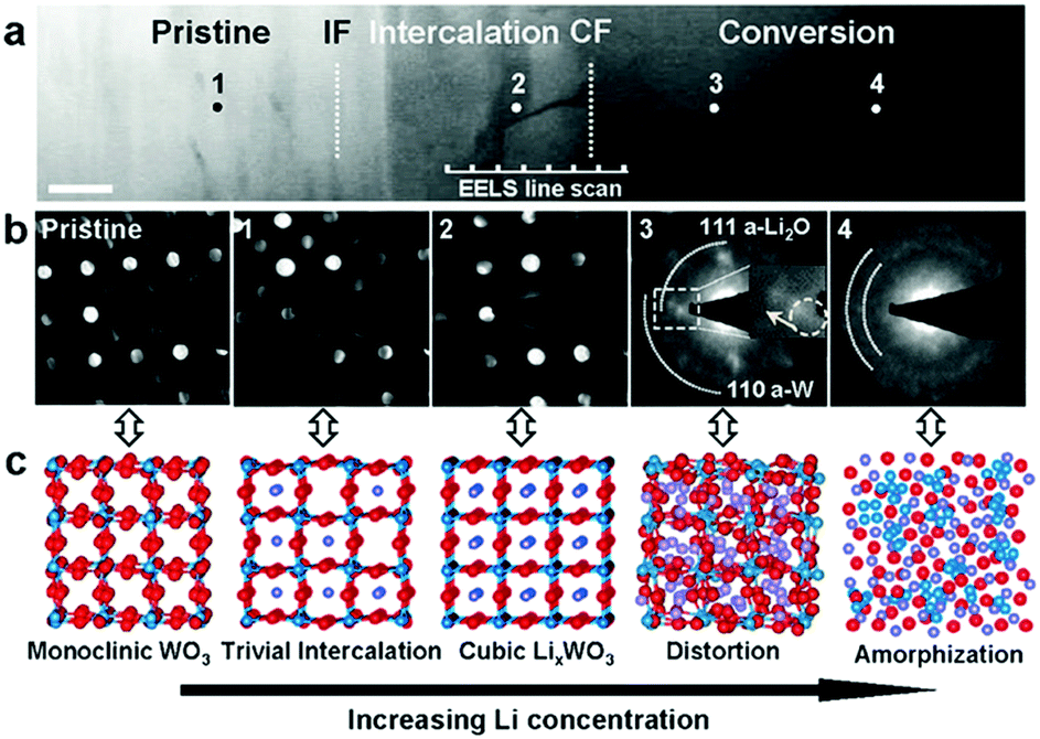 | ||
| Fig. 15 (a) HAADF images showing WO3 structure evolution during Li insertion (lithiation). Scale bar, 50 nm. (b) Nano beam diffractions (NBD) from the pristine sample and across the conversion front. (c) Structure and symmetry evolution with increasing Li concentration in the LixWO3 lattice as indicated by the corresponding NBDs. Reproduced with permission.212 Copyright 2016, Wiley. | ||
3. Binary metal oxides
Binary metal oxides (AxByOz, A = Mn, Fe, Co, Ni, and Cu; B = Mn, Fe, Co, Ni, or Cu; A ≠ B) based on conversion reactions have two electrochemical active transition metal ions and show exciting electrochemical properties as LIB anodes. In the first lithiation, two metal nanoparticles (A and B metals) are reduced and dispersed in the Li2O matrix. After full delithiation, a mixture of two metal oxides (AOx and BOy) is formed, replacing the original binary metal oxide (AxByOz). The relevant electrochemical reactions can be summarized as follows:| AxByOz + 2zLi+ + 2ze− → xA + yB + zLi2O (first lithiation) | (21) |
| A + B + (x + y)Li2O → AOx + BOy + 2(x + y)Li+ + 2(x + y)e− (first delithiation) | (22) |
| AOx + BOy + 2(x + y)Li+ + 2(x + y)e− ↔ A + B + (x + y)Li2O | (23) |
In this section, binary metal oxides are divided to three parts: AB2O4 type (AMn2O4, AFe2O4, and ACo2O4) spinel structure oxides, ABO4 type (AMoO4), and other binary metal oxide types (ABO2, ABO3, and A2B3O8). The structure and electrochemical performance of these materials are reviewed as follows.
3.1. AB2O4 type
AB2O4 type binary metal oxides always have spinel structures. They have attracted considerable interest owing to the complementarity and synergy of the two transition metal oxides during discharge–charge processes. These oxides usually exhibit better electrical conductivity and higher electrochemical activity than mono-metal oxides; thus, they are more attractive in energy storage and conversion applications.221,222 When used as LIB anodes, AB2O4 type binary metal oxides deliver high theoretical specific capacity (≈1000 mA h g−1) by transferring 8 electrons. However, the enormous volume expansion during lithiation often leads to poor cycling performance.Diverse structures, such as nanoparticles,223 nanorods,224 nanofibers,225 hollow microcubes,226 multi-shelled hollow spheres,227 microspheres,228–230 hierarchical nanostructures,231,232 and multi-level nanotubes,233 have been prepared. A facial method of electrospinning followed by controlled heat treatment has been applied to the synthesis of shrinkable CoMn2O4 tube-in-tube nanotubes.233 As observed in Fig. 16a, the shrinkable tube-in-tube nanotubes are composed of inner tubes and outer tubes. The HR-TEM image in Fig. 16b indicates that this tube-in-tube architecture is composed of uniform nanoparticles (∼10 nm in diameter). The corresponding SAED pattern (inset of Fig. 16b) suggests their polycrystallinity. These multilevel nanotubes possess large specific surface areas, fast mass transport, good strain accommodation, and high packing density. Benefiting from these advanced structural features, the CoMn2O4 tube-in-tube nanotubes deliver a high discharge capacity of ∼565 mA h g−1 at an extremely high current density of 2.0 A g−1 (Fig. 16c) and maintain a capacity of 89% after 500 cycles when tested as a LIB anode. Furthermore, carbon-coated CoMn2O4 triple-shelled hollow spheres have been fabricated by Lou's group (Fig. 16d).227 A specific capacity of 726.7 mA h g−1 and a capacity retention of almost 100% after 200 cycles were achieved by their as-prepared electrode (Fig. 16e). This superior performance is attributed to the unique multi-shelled structure with a porous, hollow interior, in which the high surface area leads to an enhanced electrode–electrolyte contact area, the hollow interior provides additional voids to alleviate volume expansion, and the multi-shelled structure provides highly stable structural support to preserve the integrity of the electrodes. Kang et al. reported porous hierarchical NiMn2O4/C tremella-like nanostructures obtained through a simple solvothermal and calcination method.234 The TEM image in Fig. 16f confirms that NiMn2O4/C contains porous hierarchical tremella-like nanostructures. The SAED pattern (inset in Fig. 16f) presents its polycrystalline nature. For Li storage, the porous NiMn2O4/C nanostructures exhibit a superior specific capacity (2130 mA h g−1 within 350 cycles at 1000 mA g−1) as well as excellent long-term cycling performance. Ma et al.235 constructed Fe-doped NiMn2O4via a facile method of nanocasting followed by an annealing process. A stabilized mesoporous cubic phase was prepared by tailoring the metal precursor ratio; as a result, the tetragonal sites of NiMn2O4 were preferentially occupied by iron. The preparation procedure of Fe-doped NiMn2O4 is schematically illustrated in Fig. 16g. The procedure begins with the amination of commercial BPPO (bromomethylated poly(2,6-dimethyl-1,4-phenylene oxide)) grafted to the polymer surface with hydroxyl groups, followed by a modified breath figure (BF) method. Subsequently, functionalized BPPO as the template is mixed with cations (Fe2+, Ni2+, and Mn3+). Finally, the metal hydroxides are converted into metal oxides by oxidative decomposition of the template. The obtained Fe-doped NiMn2O4 exhibits a high reversible capacity of 620 mA h g−1 after 250 cycles at 0.2 A g−1, good rate capability up to 2.0 A g−1, and an ultralong cycle life stability for 1200 cycles. This outstanding Li-storage performance can be attributed to the iron doping, which improves the electrical conductivity and structural robustness.
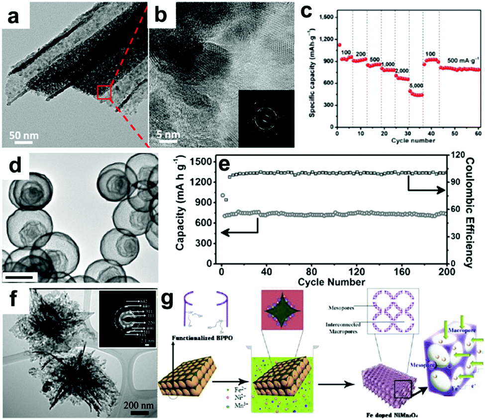 | ||
| Fig. 16 (a and b) TEM images, inset in (b) SAED patterns, and (c) rate performance of shrinkable CoMn2O4 tube-in-tube nanotubes in LIBs. Reproduced with permission.233 Copyright 2016, Springer. (d) TEM image and (e) cycling performance and corresponding coulombic efficiency at a current density of 200 mA g−1 of carbon-coated CoMn2O4 triple-shelled hollow spheres. Reproduced with permission.227 Copyright 2014, Wiley. (f) TEM image, inset in (f) SAED patterns of porous hierarchical tremella-like NiMn2O4/C. Reproduced with permission.234 Copyright 2015, RSC. (g) Schematic of the synthesis of Fe-doped NiMn2O4. Reproduced with permission.235 Copyright 2015, ACS. | ||
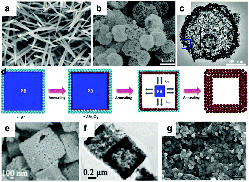 | ||
| Fig. 17 (a) SEM image of CoFe2O4 nanowire arrays. Reproduced with permission.236 Copyright 2015, RSC. (b) SEM and (c) TEM images of hierarchical porous ball-in-ball hollow spheres of CoFe2O4. Reproduced with permission.242 Copyright 2014, Springer. (d) Synthetic process of the spinel AFe2O4 (A = Co, Ni) hollow structures. (e) SEM and (f) TEM images of NiFe2O4 cubes. Reproduced with permission.241 Copyright 2015, ACS. (g) SEM image of CoFe2O4/graphene nanocomposites. Reproduced with permission.251 Copyright 2014, Elsevier. | ||
In order to enhance the conductivity of electrodes, conductive materials such as graphene,243–248,251 CNT249 and carbon nanofiber250 have been combined with AFe2O4. Mesoporous CoFe2O4 nanospheres cross-linked with CNTs (CFO/CNT) have been prepared by a feasible one-pot solvothermal method.249 Firstly, the CNTs, as common metal ion adsorbents, adsorb Co2+ and Fe2+. Subsequently, these metal ions accumulate on the surface of the CNTs with increasing autoclave temperature. As a result, small crystals are obtained and then aggregate into CFO nanoparticles, which are further assembled into CFO nanospheres. With stable electronic and ionic transfer channels and short Li+ ion diffusion lengths supplied by the CFO/CNT composites, they manifest excellent rate performance. Li et al. prepared CoFe2O4/graphene nanocomposites via a facile one-step method, as shown in Fig. 17g.251 It is noteworthy that almost all CoFe2O4 nanoparticles can be encapsulated within graphene sheets, which efficiently prevents aggregation of the particles and avoids direct contact between the CoFe2O4 nanoparticles and the electrolyte. Hence, CoFe2O4/graphene delivers enhanced rate capability and long cycling stability.
In contrast to the numerous studies on NiFe2O4 and CoFe2O4, there are fewer reports on MnFe2O4 and CuFe2O4. The research on CuFe2O4 mainly focuses on the preparation of nanostructures as well as some hybrid materials, such as nanofibers,252,253 hollow spheres,254 CoFe2O4/graphene,255 and polypyrrole-coated CuFe2O4.256 Hollow CuFe2O4 spheres encapsulated in carbon shells have been reported by Jin et al.254 When used as an anode for LIBs, the electrode based on hollow CuFe2O4 spheres encapsulated in carbon shells exhibits high specific capacity, good cycling stability, and excellent rate performance. Even after 70 cycles, a high specific capacity of 550 mA h g−1 is retained. Zhao et al. have fabricated CuFe2O4 hollow fibers by a simple electrospinning method followed by heat treatment.253 Qian's group prepared porous MnFe2O4 microrods as a promising LIB anode.257 The microrods are composed of many interconnected nanoparticles, forming a porous structure. Due to this unique structure, the porous MnFe2O4 electrode exhibits outstanding cycling stability (a capacity of 630 mA h g−1 is retained after 1000 cycles at 1.0 A g−1) as well as extraordinary rate performance.
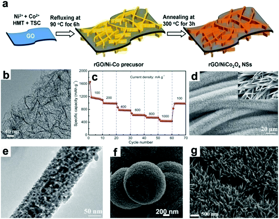 | ||
| Fig. 18 (a) The synthesis procedure, (b) TEM image, and (c) rate performance of rGo/NiCo2O4. Reproduced with permission.265 Copyright 2014, Wiley. (d) SEM and (e) TEM images of NiCo2O4/carbon textiles. Reproduced with permission.266 Copyright 2014, Wiley. (f) SEM image of MnCo2O4 microspheres. Reproduced with permission.229 Copyright 2013, RSC. (g) SEM image of FeCo2O4 nanoneedles array. Reproduced with permission.279 Copyright 2016, ACS. | ||
In addition, MnCo2O4 has aroused a great deal of interest. Different morphologies of MnCo2O4 have been fabricated, such as nanoparticles,269 mesoporous spheres,228–230,270,271 nanosheets,272 nanoflakes,273 core–shell structures,274 and MnCo2O4/PPy.275 Qian's group synthesized porous MnCo2O4 quasi-hollow spheres for Li storage.229 The hollow interiors of MnCo2O4 microspheres are depicted in the SEM image shown in Fig. 18f. It should be noted that the walls of the hollow structures are extremely thick. When evaluated as an anode for LIBs, the MnCo2O4 electrode maintains a stable capacity of 610 mA h g−1 at 0.4 A g−1 after 100 cycles.
Recently, porous CuCo2O4 nanocubes,276 hollow FeCo2O4 nanospheres,277 FeCo2O4 nanoflakes,278 porous FeCo2O4 nanoneedle arrays on nickel foam,279 and self-assembled mesoporous FeCo2O4280 were also investigated. Liu et al.279 have fabricated porous FeCo2O4 monocrystalline nano-needle arrays on nickel foam by a hydrothermal technique combined with subsequent calcination. The SEM image presented in Fig. 18g reveals that the FeCo2O4 nanoneedle arrays present an open framework. Owing to the merits of effective conductive transport paths, shorter ion transfer distances, and binder-free electrodes by direct growth on nickel foam, the obtained FeCo2O4 nanoneedle arrays display a high specific capacity of 1962 mA h g−1 at 0.1 A g−1 and superior rate capability (a capacity of 875 mA h g−1 at 2.0 A g−1).
3.2. ABO4 (AMoO4, A = Mn, Fe, Co, Ni)
ABO4 type binary metal oxides are mainly Mo-containing mixed oxides (MnMoO4,284 FeMoO4,281,285 CoMoO4,282,286–291 and NiMoO4283,292–294). They are attractive for their high oxidation state as ‘‘hosts’’ for reacting with lithium, delivering 8 mol electrons per mol of material and achieving a high theoretical capacity of about 1000 mA h g−1. Guan and coworkers prepared MnMoO4 and coated it with carbon by a hydrothermal treatment.284 Their MnMoO4@C composite anode achieved a high reversible capacity of 1050 mA h g−1 even after 200 cycles at 0.1 A g−1 with the reversible reactions between the Mo and Mn nanoparticles and MnO and MoO3. Monodisperse FeMoO4 nanocubes with sizes of about 100 nm were prepared by Qian's group via a one-pot hydrothermal method, as depicted in Fig. 19a.281 They observed the morphology changes during the growth of FeMoO4 nanocubes and found that the defined single-crystalline cubes were self-aggregated by nanosheets. They studied the Li storage behavior in FeMoO4 (Fig. 19b) and proposed the electrochemical reactions as follows:| FeMoO4 + xLi+ + xe− → LixFeMoO4 | (24) |
| LixFeMoO4 + (8 − x)Li+ + (8 − x)e− → Fe0 + Mo0 + 4Li2O | (25) |
| Fe0 + Li2O ↔ FeO + 2e− + 2Li+ | (26) |
| Mo0 + 3Li2O ↔ MoO3 + 6e− + 6Li+ | (27) |
| MoO3 + yLi+ + ye− → LiyMoO3 | (28) |
| LiyMoO3 + (6 − y)Li+ + (6 − y)e− → Mo + 3Li2O | (29) |
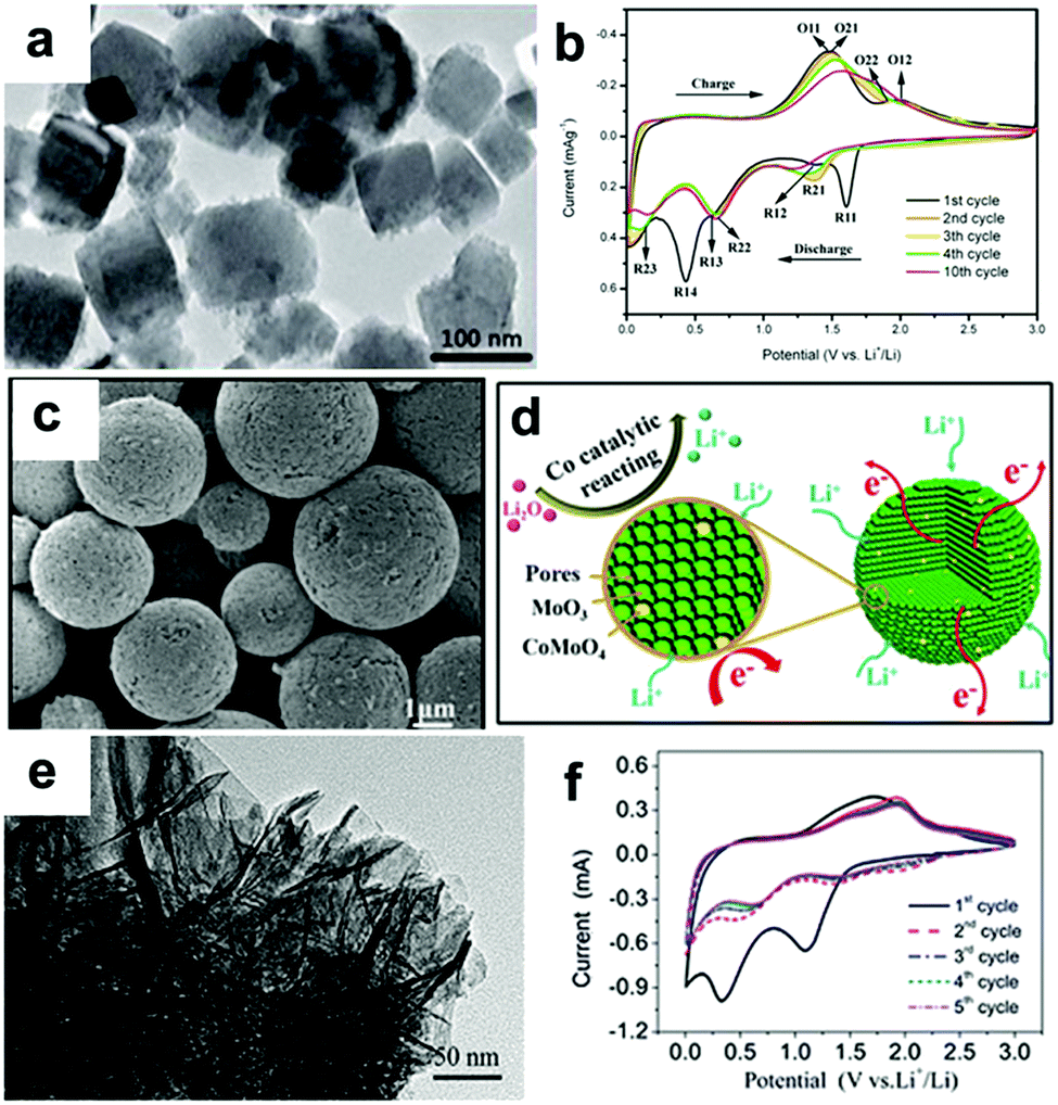 | ||
| Fig. 19 TEM image (a) and CV curves (b) of FeMoO4 nanocubes; reproduced with permission.281 Copyright 2015, Wiley. SEM image (c) and schematic of the lithiation–delithiation process (d) in porous MoO3−CoMoO4 hybrid microspheres (P-Mo–Co-HMSs); reproduced with permission.282 Copyright 2016, ACS. TEM image (e) and CV curves (f) of the NiMoO4@3DGF composites. Reproduced with permission.283 Copyright 2015, RSC. | ||
Electrochemical characterization suggested that the FeMoO4 nanocubes anode achieves a high reversible capacity of 926 mA h g−1 at 0.1 A g−1 as well as excellent rate performance. A FeMoO4 nanorods anode was also prepared and exhibited a high reversible capacity of 1110 mA h g−1 at 1 C (1 C = 992.3 mA g−1) after 1000 cycles.285 Its excellent electrochemical performance indicates that FeMoO4 is a promising LIB anode material.
CoMoO4 has a high theoretical specific capacity of 980 mA h g−1 when used as a LIB anode material; however, its low electronic conductivity and volume changes during cycling result in rapid capacity loss and inferior rate capability, hampering its practical applications. Ajayan and coworkers fabricated nanosized CoMoO4 particles of 3 to 5 nm and dispersed them on reduced graphene oxide (rGO).291 Yang et al. prepared a hybrid composite of CoMoO4 nanorods and rGO.288 Using an electrospinning method,295 lotus root-like CoMoO4@graphene nanofibers have been prepared.286 The high surface area and multi-level porous structure of rGO not only improves the conductivity of the CoMoO4/rGO composites but also shortens the Li+ diffusion distance during cycling, endowing the hybrid materials with good electrochemical performance. Chen et al. constructed 3D hierarchical CoMoO4/polypyrrole (PPy) core–shell nanowire (NW) arrays on conductive and flexible carbon cloth and evaluated them as binder-free LIB anodes for half-cells and full cells.289 The structural integrity and mechanical strength of the binder-free electrode were guaranteed by the direct growth method. The outside PPy layers not only enhanced the conductivity of the electrode but also effectively accommodated the volume expansion of the CoMoO4 NWs during cycling. Due to its well-designed nanostructure, their CoMoO4/PPy hybrid anode achieved a stable reversible capacity of 764 mA h g−1 after 1000 cycles at 1.2 A g−1. When coupled with commercial cathode LiFePO4, the full cell using CoMoO4/PPy hybrid as the anode achieved a high cycling stability (stable capacity was exhibited at 0.4 A g−1 even after 1000 cycles).
Recently, porous MoO3−CoMoO4 hybrid microspheres (P-Mo−Co-HMSs) with homogeneously dispersed MoO3 and CoMoO4 subunits were synthesized by Wang et al.292 As shown in Fig. 19c, the surface of the microspheres possesses an obvious pore structure, which is particularly beneficial for creating more active sites, enlarging the contact area of the active material with the electrolyte, and shortening the Li ion diffusion distance. Benefiting from these appealing structural and component features, the P-Mo−Co-HMSs anode exhibits excellent electrochemical performance, such as high capacity (1598.7 mA h g−1 after 100 cycles at 0.2 A g−1), superior cycling stability, and excellent rate capability (640 mA h g−1 at 3.0 A g−1). The introduction of CoMoO4 is believed to be responsible for the superior lithium storage performance. As depicted in Fig. 19d, the in situ formed Co nanoclusters from CoMoO4 not only promoted the reversible formation and decomposition of Li2O but also functioned as an excellent buffer matrix for the MoO3 electrode, preventing the aggregation of Mo nanograins and buffering volume changes and structural stress of the electrode during cycling. Thus, excellent electrochemical performance was achieved by the composite electrode.
NiMoO4 has been investigated as anode material for LIBs. The two main polymorphs, α-NiMoO4 and β-NiMoO4, are both monoclinic but have different Mo coordinations. Mo6+ ions occupy octahedral sites in α phase and tetrahedral sites in β phase.296 The α phase is stable at room temperature, while the β phase begins to crystallize between 550 °C and 670 °C; it is difficult to prepare pure β phase. Ahn et al. prepared phase-pure β-NiMoO4 yolk–shell spheres using nickel nitrate, ammonium molybdate, and sucrose as the starting material by a one-pot spray pyrolysis method.294 Amorphous dense spheres and α/β-NiMoO4 yolk–shell spheres were also prepared by controlling the post-annealing temperature. Their results suggested that the electrochemical performance of the phase-pure β-NiMoO4 yolk–shell spheres is significantly superior to those of other samples. Honeycomb-like NiMoO4 ultrathin nanosheet arrays on Ni foam293 were fabricated and evaluated as binder-free LIB anodes; a high capacity of 680 mA h g−1 was obtained at 1.0 A g−1 after 200 cycles. Wang et al. constructed 3D NiMoO4 nanowire arrays292 and network-like porous NiMoO4 nanoarchitectures (NiMoO4@3DGF)283 on a 3D graphene network combining a chemical vapor deposition (CVD) method and a hydrothermal route. As the TEM image in Fig. 19e depicts, the interconnected network-like nanostructures of the porous NiMoO4 nanoarchitectures consist of ultrathin crooked nanosheets. The adjacent nanosheets are self-assembled into continuous, interconnected porous architectures. When these nanoarchitectures were evaluated as a LIB anode, two obvious reduction broad peaks appeared at 0.33 and 1.09 V as Li intercalation proceeded in the NiMoO4@3DGF anode, as shown in Fig. 19f. These two peaks can be assigned to the reduction of NiMoO4 to metallic Ni and Mo, accompanying the formation of the SEI layer. The anodic peaks at 1.38 and 1.7 V are attributed to the oxidation of Mo and Ni nanograins to Mo6+ and Ni2+, respectively. In subsequent cycles, two pairs of redox peaks were induced by the reversible reactions of MoO3 and NiO between Mo and Ni metal. The Li storage behavior in the as-prepared NiMoO4@3DGF composite anode can be expressed as follows:
| NiMoO4 + 8Li+ + 8e− → Ni + Mo + 4Li2O | (30) |
| Ni + Li2O → NiO + 2Li+ + 2e− | (31) |
| Mo + 3Li2O → MoO3 + 6Li+ + 6e− | (32) |
| Ni + Mo + 4Li2O ↔ NiO + MoO3 + 8Li+ + 8e− | (33) |
3.3. Other types of binary metal oxides (ABO2, ABO3, and A2B3O8)
In addition to AB2O4 and ABO4 types, other binary metal oxides have been studied as LIB anodes, such as ABO2 type (CoNiO2297 and CuFeO2298,299), ABO3 type (FeMnO3300,301), and A2B3O8 type (Fe2Mo3O8,302 Mn2Mo3O8,303,304 and Co2Mo3O8,305,306). Suffering from low conductivity and volume changes, electrodes with various hierarchical structures combined with carbon-based materials have been rationally designed and synthesized, achieving high reversible capacities and long cycling stabilities. The electrochemical performances of these materials are summarized in Table 1. Among these, the lithiation and delithiation products of Mn2Mo3O8 are ambiguous, although a high capacity was achieved. As reported by Chowdari,303,307 only Mo in Mn2Mo3O8 can be reduced to Mo metal, while the Mn remains as MnO; this is different from the mechanism of other binary metal oxides. This is interesting and worthy of clarification.| Materials | First discharge/charge capacity (mA h g−1) | Capacity (mA h g−1)/cycle number, (current density, A g−1) | Capacity (mA h g−1)/current density (A g−1) | Ref. |
|---|---|---|---|---|
| Mesoporous CoNiO2 | 941.3/617.1 | 449.3/50th (0.1) | 66/5 | 297 |
| CuFeO2/G composites | 1571/944 | 670/100th (0.14) | 440/0.7 | 298 |
| FeMnO3 particles | —/— | 984/500th (1.0) | 282/8.0 | 300 |
| MnFeO3/MWCNT | 1524/1049 | 840/50th (0.2) | 410/10.0 | 301 |
| Fe2Mo3O8–rGO | 1275.2/923.5 | 835/40th (0.2) | 574.8/3.0 | 302 |
| Mn2Mo3O8–graphene | 921/— | 950/40th (0.2) | 671/1.5 | 304 |
| Co2Mo3O8/rGO | 1834/1170 | 954/60th (0.06) | 503/1.0 | 305 |
4. Conversion-alloying metal oxides
Conversion-alloying metal oxides, mainly including SnO2, Sn3O4, GeO2, and ZnO, are achieved in two steps of conversion and alloying reactions when reacting with lithium.SnO2 is an outstandingly attractive LIB anode candidate due to its abundance, environmental benignity, and high theoretical capacity. The key obstacle encountered by SnO2 anodes is the large volume change (≈358%) during the charge/discharge process, which leads to poor cycling stability and rate performance. It is widely believed that the lithium storage mechanism of SnO2 anodes involves two steps, as follows:
| SnO2 + 4Li+ + 4e− → Sn + 4Li2O (first lithiation) | (34) |
| Sn + 4.4Li+ + 4.4e− ↔ Li4.4Sn | (35) |
In this mechanism, the first step is irreversible and the second step is reversible.308–310 From this standpoint, SnO2 anode delivers a theoretical specific capacity of 780 mA h g−1 by transferring 4.4 moles of Li ions per mole of Sn. However, some researchers consider that both steps are reversible when SnO2 possesses a nanoscale structure.311–313 In this case, the theoretical specific capacity for SnO2 is 1494 mA h g−1 (transferring 8.4 moles of Li ions per mole of SnO2). Hu et al. insisted that suppressing in situ formed coarse Sn, constructing numerous Sn/Li2O interfaces, and maintaining durable nanostructures in the electrode are greatly significant to obtain highly reversible SnO2 electrodes.313 In order to confirm this point, they synthesized a thin-film SnO2 electrode with large numbers of interfaces and grain boundaries by a magnetron sputtering method. Aided by XRD, electron energy loss spectroscopy (EELS), XPS and in situ surface-enhanced Raman scattering (SERS), they concluded that all the metallic Sn in the lithiated film electrode was completely re-oxidized to amorphous SnO2. This work confirms that the particle size of SnO2 influences the reversibility of the conversion reaction. Therefore, researchers have concentrated on decreasing the size of the SnO2 particles,311,314,315 constructing nanostructured SnO2316–318 and preparing SnO2-conductive material hybrids.312,319–322 Wang and co-workers prepared N-doped SnO2 nanoparticles through a laser-assisted pyrolysis method.311 The unreactive Sn–N bonds and small particle sizes resulted in exceptional electrochemical performance (a reversible capacity of 1192 mA h g−1 after 500 cycles at 1.4 A g−1). Polydopamine-coated SnO2 nanocrystals were synthesized by a polymer-templated method.312 The establishment of a passivating SEI layer resulted from the introduction of PDA; also, the corn-like nanostructure contributed to the outstanding rate capability and superior long-term stability. Hollow structure materials are widely used in LIBs due to their hollow interiors, which supply additional volume to alleviate structural strain, contributing to superior electrochemical performance. Uniform multi-shelled SnO2 hollow microspheres were synthesized by Wang's group via a sequential hard template method.310 They prepared single-, double-, triple-, and quadruple-shelled SnO2. Fig. 20a and b display the SEM images of triple- and quadruple-shelled SnO2, respectively. Fig. 20c shows the CV curves of the multi-shelled SnO2 hollow microsphere in the first three cycles. In the first cycle, an intensive cathodic peak around 0.73 V is associated with the reduction of SnO2 to Sn and the formation of SEI layers. The peak near 0.15 V is ascribed to the formation of LixSn. The peaks at about 0.1 V and 0.53 V that appeared in the anodic process are attributed to lithium dealloying from LixSn. The weak oxidation peaks at 1.25 V and 1.81 V may be due to the reversible reaction from Sn to SnO2. In the subsequent cycles, the cathodic peaks at 0.92 V and 1.17 V, together with the anodic peaks at 1.25 V and 1.81 V, correspond to the partially reversible reaction between Sn and SnO2. In virtue of the sufficient void space offered by the multi-shelled structure, the volume change during cycling could be effectively buffered and more lithium storage sites are exposed. Hence, the multi-shelled SnO2 hollow microsphere anode demonstrates superior rate capacity, good cycling performance, and excellent structural stability.
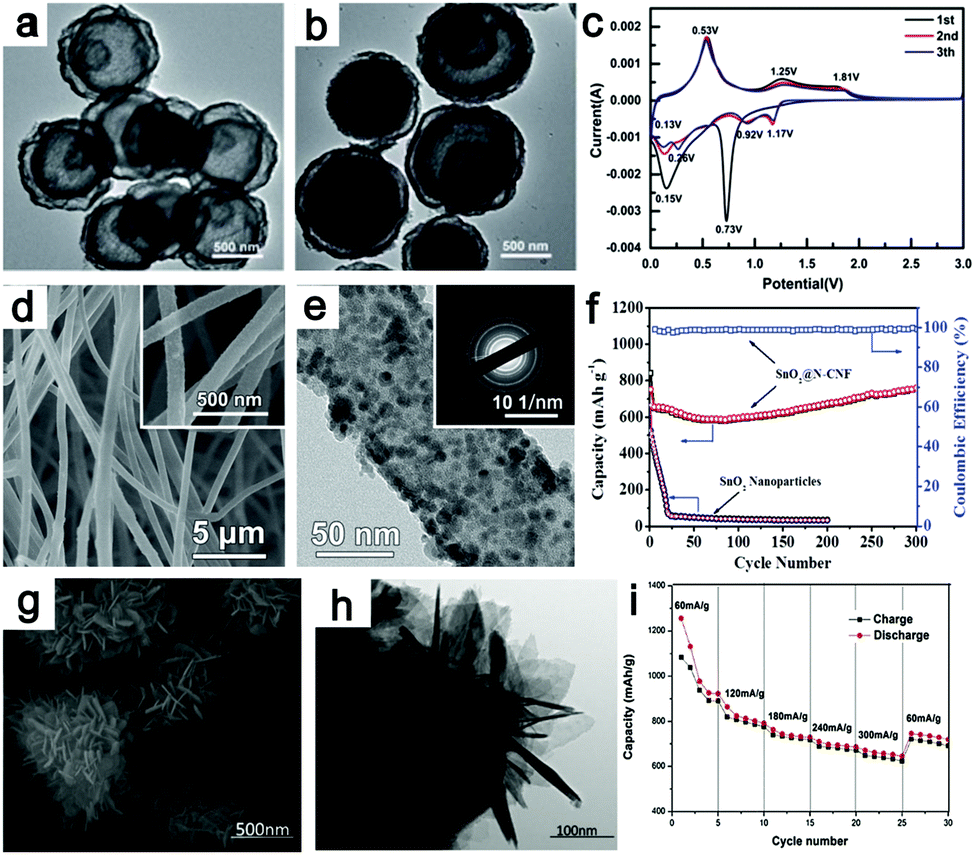 | ||
| Fig. 20 TEM images of triple-shelled SnO2 (a) and quadruple-shelled SnO2 (b); (c) cyclic voltammetry profiles of quadruple-shelled SnO2 hollow microspheres at a scan rate of 2 mV s−1. Reproduced with permission.310 Copyright 2016, RSC. (d) SEM, (e) TEM and inset in (e) SAED pattern of SnO2@N-CNF; (f) cycling performance of SnO2@N-CNF and commercial SnO2 nanoparticles. Reproduced with permission.314 Copyright 2016, Wiley. (g) SEM image, (h) TEM image and (i) rate performance of hierarchical flower-like Sn3O4. Reproduced with permission.325 Copyright 2015, Elsevier. | ||
Fabricating nanostructures in carbon matrices can effectively restrain the aggregation of SnO2 particles and improve the conductivity.314,321–323 Qiao et al.314 encapsulated SnO2 nanoparticles in flexible nitrogen-doped carbon nanofiber films (denoted as SnO2@N-CNF) by electrospinning. The fibrous morphology of SnO2@N-CNF can be observed in Fig. 20d. Furthermore, the TEM image shown in Fig. 20e clearly indicates that SnO2 nanoparticles with sizes of about 7.5 nm are well dispersed in the carbon nanofibers. Extraordinary rate performance and long-term cycling stability were obtained, which can be attributed to the unique nanostructure of SnO2. As shown in Fig. 20f, the cycling performance of SnO2@N-CNF is much better than that of commercial SnO2 nanoparticles. Specifically, graphene, an attractive conductive material, is usually used to improve the conductivity of SnO2 by forming SnO2/graphene.315,319,320,324 SnO2 quantum dots (QDs) supported by graphene nanosheets (GNSs) were fabricated via a hydrothermal method and electron-beam irradiation (EBI) strategies.319 The EBI technique can induce the exfoliation of GNSs and increase their interlayer spacing, leading to increases in GNS amorphization, disorder, and defects. The ultrasmall SnO2 quantum dots (3 to 5.5 nm) and the addition of graphene are beneficial to the utilization and conductivity of the active material.
There are few studies of Sn3O4 as a LIB anode. Chen et al.325 reported the use of hierarchical flower-like Sn3O4 as a LIB anode material. The flower-like Sn3O4 was assembled with single-crystalline Sn3O4 nanosheets, which can be clearly observed in the SEM and TEM images shown in Fig. 20g and h, respectively. The unique structure possesses a large inner space and a high surface area, which not only facilitate liquid electrolyte diffusion but also provide abundant room to retain volume expansion. A reversible capacity of 505.2 mA h g−1 was obtained after 50 cycles. Additionally, superior rate performance was also obtained, as shown in Fig. 20i. The electrochemical reactions may proceed as follows:
| Sn3O4 + 8Li+ + 8e− → 3Sn + 4Li2O (first lithiation) | (36) |
| Sn + xLi+ + xe− ↔ LixSn (x ≤ 4.4) | (37) |
Germanium oxide (GeO2) is another conversion-alloying anode material whose Li storage behavior resembles that of SnO2. Owing to its high theoretical capacity (1125 mA h g−1), low operation voltage (0.7 V to 0 V vs. Li+/Li) and higher thermal stability, GeO2 anode has attracted the attention of researchers.332–337 For example, Guo's group synthesized Ge/GeO2/C by calcinating GeO2 in C2H2/Ar at 650 °C.335 When used as a LIB anode, the kinetics of the conversion reaction of the as-prepared GeO2/Ge/C anode was largely activated and improved by the combination of fine nanparticles, carbon coating, and the elemental Ge in the composite. As a consequence, the Ge/GeO2/C nanocomposites anode delivered a capacity of 1680 mA h g−1 at 10C (C = 2.1 A g−1) rate, demonstrating high capacity and good rate capability.
As an anode material, ZnO has a high theoretical capacity (987 mA h g−1) and a higher lithium-ion diffusion coefficient.326 However, it usually demonstrates poor electrical conductivity and large volume variations during cycling, leading to limited rate performance. The electrochemical reactions of ZnO electrode are proposed as follows:
| ZnO + 2Li+ + 2e− ↔ Zn + Li2O | (38) |
| Zn + xLi+ + xe− ↔ LixZn (x ≤ 1) | (39) |
Recently, a great deal of progress on ZnO anodes has been reported.326–331 Among these, ZnO@ZnO quantum dots/C core–shell nanorod arrays (ZnO@ZnO QDs/C NRAs) grown on carbon cloth as an anode for LIBs have been synthesized by Zhang et al.326 Benefiting from the shortened Li+ diffusion distance, superior conductivity, and good structural stability of the nanorod arrays, ZnO@ZnO QDs/C NRAs manifest a remarkable rate capability and excellent cycling performance.
5. Summary and outlook
We have summarized recent progress in the use of conversion reaction metal oxides as LIB anodes. The typical characteristics of the materials, including theoretical capacity, cathodic voltage, anodic voltage, and their formed products are listed in Tables 2 and 3 according to the consensus of reported studies. Obviously, the usage of conversion reaction metal oxides is promising to obtain advanced Li-ion batteries with large capacities. Unfortunately, several obstacles remain to be overcome before this promise can become reality. Concentrating on the low electronic conductivity and volume expansion, various micro/nanostructure electrodes are currently being rationally designed by combining two or more of the three approaches mentioned in the introduction; these electrodes exhibit satisfied reversible capacity and cycling stability. It should be pointed out that currently, the reversible specific capacities of the electrodes are mostly calculated based on the mass loading of the active materials, ignoring their volume-specific capacities. It is well known that nanoscale powder materials have relatively low packing densities, which severely lowers the volumetric capacities of electrodes. Assuming that the capacity and tapping density of the graphite anode are 372 mA h g−1 and 2.0 g cm−3, respectively, the volume specific capacity of graphite is calculated to be 744 mA h cm−3. This means that only oxides with tapping densities of at least 1.0 g cm−3 and specific capacities of 744 mA h g−1 can compete with graphite anode. Therefore, it is necessary to consider tapping density during the design and synthesis of oxide anodes. Additionally, the voltage hysteresis observed between the discharge and charge plateaus is also always overlooked, which severely diminishes the electrode round-trip efficiency. Unfortunately, the origins of the hysteresis are ambiguous, and the controversy regarding traditional kinetic and thermodynamics factors remains. A similar situation troubles Li–air batteries. The cleavage of stable Li–O bonds is a common factor between Li-ion batteries based on conversion reaction metal oxides and Li–air systems; the rational design and incorporation of catalysts may be an alternative to address the voltage hysteresis observed in these electrodes.| Material | Theoretical capacity (mA h g−1) | Reduction potential (V, vs. Li+/Li) | Reduction products | Oxidation potential (V, vs. Li+/Li) | Oxidation products | Ref. |
|---|---|---|---|---|---|---|
| Cr2O3 | 1058 | 0.7 | Cr | 1.1 | Cr2O3 | 176 |
| MnO | 755 | 0.2–0.4 | Mn | 1.2–1.3 | MnO | 56, 62 and 338 |
| Mn3O4 | 936 | 0.2–0.4 | Mn | 1.2–1.4 | Mn3O4 | 63, 339 and 340 |
| Mn2O3 | 1018 | 0.2–0.4 | Mn | 1.2–1.4 | MnO, Mn3O4 | 26, 44 and 45 |
| Fe2O3 | 1007 | 0.8–1.0 | Fe | 1.7–1.9 | Fe2O3 | 96 and 341 |
| Fe3O4 | 924 | 0.8–1.0 | Fe | 1.6–1.9 | FeO, Fe3O4 | 74, 92 and 342 |
| CoO | 716 | 1.1–1.5 | Co | 1.9–2.2 | CoO | 99, 343 and 344 |
| Co3O4 | 954 | 0.9–1.4 | Co | 2.0–2.3 | CoO, Co3O4 | 106, 111, 112 and 345 |
| NiO | 718 | 0.9–1.2 | Ni | 2.–1–2.3 | NiO | 139, 140 and 346 |
| Cu2O | 375 | 1.0–1.1 | Cu | 2.3–2.5 | Cu2O | 164 and 347 |
| CuO | 674 | 1.17, 0.72 | Cu2O, Cu | 2.4–2.5 | CuO | 143 and 154 |
| MoO2 | 837 | 1.55, 1.26, 0.29 | LiMoO2, Mo | 1.47, 1.72 | MoO2 | 196 and 199 |
| MoO3 | 1117 | 2.3, 0.3 | LixMoO2, Mo | 1.5 | MoO3 | 191 and 348 |
| WO3 | 693 | 0.6–0.9 | W | 1.2–1.3 | WO3 | 208 and 220 |
| Material | Theoretical capacity (mA h g−1) | Reduction potential (V, vs. Li+/Li) | Reduction products | Oxidation potential (V, vs. Li+/Li) | Oxidation products | Ref. |
|---|---|---|---|---|---|---|
| AMn2O4, A = | ||||||
| Co | 921 | 0.47, 1.25 | Mn, Co | 1.44, 2.03 | MnO, CoO | 225 and 226 |
| Ni | 922 | 0.42, 1.13 | Mn, Ni | 1.32, 1.98 | MnO/Mn3O4, NiO | 234 and 235 |
| AFe2O4, A = | ||||||
| Mn | 930 | 0.76 | Mn, Fe | 1.67–2.02 | MnO, Fe3O4 | 257 |
| Co | 914 | 0.75 | Co, Fe | 1.6–1.9 | CoO, Fe2O3 | 244 |
| Ni | 915 | 0.84, 0.98 | Fe, Ni | 1.68 | NiO, Fe2O3 | 241 and 349 |
| Cu | 897 | 0.88 | Fe, Cu | 1.7–1.9 | CuO, Fe2O3 | 252 and 350 |
| ACo2O4, A = | ||||||
| Mn | 906 | 0.85 | Mn, Co | 2.27 | MnO, CoO | 229 |
| Fe | 902 | 0.72, 1.57 | Fe, Co | 1.68, 2.25 | FeO, Co3O4 | 278 and 279 |
| Ni | 892 | 0.81–1.25 | Ni, Co | 1.5–1.7, 2.1–2.3 | NiO, Co3O4 | 265 and 267 |
| Cu | 874 | 0.8–1.3 | Cu, Co | 2.0–2.3 | CuO, Co3O4 | 351 and 352 |
| AMoO4, A = | ||||||
| Mn | 998 | — | Mn, Mo | — | MnO, MoO3 | 284 |
| Fe | 994 | 0.67, 1.37 | Fe, Mo | 1.5, 2.0 | FeO, MoO3 | 281 |
| Co | 980 | 0.64, 1.55 | Co, Mo | 1.4, 1.8 | MoO3, CoO | 286 |
| Ni | 980 | 1.0, 1.75 | Ni, Mo | 1.48, 2.25 | MoO3, NiO | 293 |
| CoNiO2 | 717 | 1.06 | Co, Ni | 2.15 | CoO, NiO | 297 |
| CuFeO2 | 709 | 1.15 | Cu, Fe | 1.68 | Cu2O, Fe2O3 | 298 |
| FeMnO3 | 1013 | 0.3, 0.8 | Mn, Fe | 1.2, 1.7 | Mn3O4, Mn2O3, Fe2O3, Fe3O4 | 300 |
In addition, researchers are currently focusing on the side effects of conversion reactions, such as volume expansion, pulverization and structural collapse, ignoring their favorable aspects. The nanosize effect is a typical characteristic of conversion reactions; this effect further reduces the dimensions of active materials, enlarges the contact area between the active material and electrolyte, and shortens the Li+ diffusion distance. These features are beneficial to enhance the electrode kinetics. Recent progress on structural changes in conversion reaction anode materials (such as Co3O4 nanocubes, FeF2 nanoparticles, RuO2 nanowires, and NiO nanosheets) using in situ TEM confirm that a conductive network is reversibly generated in conversion reactions that can provide pathways for electron transfer.105,168,353,354 When the reduction and oxidation potentials of these metal oxides are analysed, it is clear that the redox potential of MnOx is much lower than those of other oxides, such as FeOx, CoOx, and CuOx. If MnOx is mixed with other high redox potential oxides, two separate redox pairs will exist in the anode mixture. The earlier in situ formed metal network not only enables fast electron transfer but also functions as a matrix to prevent the aggregation of metal nanoparticles that form later during further lithiation processes. Upon delithiation, the metal network that was oxidated at high potential can play a dual role as a conductive network and matrix during the oxidation process of Mn metal. Meanwhile, the re-oxidated MnOx can play the role of a matrix to guarantee good dispersion of the late-formed metal oxides in return. Therefore, a self-matrix and reversible in situ formed conductive network can be fabricated if the mixture oxides are small enough (1 to 5 nm) and have a highly homogeneous dispersion. However, it is difficult to form a thorough mixture on the nanoscale within a chemical or mechanical mixture.
Taking advantage of the nanosize effect of conversion reactions, good dispersion of two or more oxides can be achieved after lithiation–delithiation, which has been confirmed by the reported binary metal oxide anodes. Combining the reversible metal conductive network and the merits of nanosize effects, a self-matrix and conductive network can be fabricated by tailoring the components of the compounds, as illustrated by a reported FeMnO3 anode.300 Other related studies have also remarked on this point recently.19,281,282 More importantly, a reconstructed hierarchical structure with an in situ formed metal conductive network can be fabricated by controlling the lithiation or delithiation state. In these reformed structures, the small oxide nanoparticles and metal nanograins can function as active sites for catalysis. It is believed that the characteristics of the conversion reaction can not only be used to fabricate high performance electrode materials but can also be exploited in further applications, such as catalysts for the oxygen reduction reaction (ORR) and oxygen evolution reaction (OER).
Acknowledgements
This work was financially supported by the National Natural Science Foundation of China (51622102, 51231003, 51571124), the Ministry of Education of China (IRT-13R30), MOST(2016YFB0901502), and the 111 Project (B12015).References
- D. Larcher and J. M. Tarascon, Nat. Chem., 2015, 7, 19 CrossRef CAS PubMed.
- S. Chu, Y. Cui and N. Liu, Nat. Mater., 2017, 16, 16 CrossRef PubMed.
- N. J. Dudney and J. Li, Science, 2015, 347, 131 CrossRef CAS PubMed.
- Y.-G. Guo, J.-S. Hu and L.-J. Wan, Adv. Mater., 2008, 20, 2878 CrossRef CAS.
- H. Wu, G. Yu, L. Pan, N. Liu, M. T. McDowell, Z. Bao and Y. Cui, Nat. Commun., 2013, 4, 1493 CrossRef PubMed.
- P. Poizot, S. Laruelle, S. Grugeon, L. Dupont and J.-M. Tarascon, Nature, 2000, 407, 496 CrossRef CAS PubMed.
- X. Rui, H. Tan and Q. Yan, Nanoscale, 2014, 6, 9889 RSC.
- F. Wang, S. W. Kim, D. H. Seo, K. Kang, L. Wang, D. Su, J. J. Vajo, J. Wang and J. Graetz, Nat. Commun., 2015, 6, 6668 CrossRef CAS PubMed.
- K. Zhang, X. Han, Z. Hu, X. Zhang, Z. Tao and J. Chen, Chem. Soc. Rev., 2015, 44, 699 RSC.
- L. Zhang, H. B. Wu and X. W. Lou, Adv. Energy Mater., 2014, 4, 1300958 CrossRef.
- D. Meggiolaro, G. Gigli, A. Paolone, P. Reale, M. L. Doublet and S. Brutti, J. Phys. Chem. C, 2015, 119, 17044 CAS.
- R. Khatib, A. L. Dalverny, M. Saubanère, M. Gaberscek and M. L. Doublet, J. Phys. Chem. C, 2013, 117, 837 CAS.
- J. Wang, H. Zhou, J. Nanda and P. V. Braun, Chem. Mater., 2015, 27, 2803 CrossRef CAS.
- M. R. Palacin, Chem. Soc. Rev., 2009, 38, 2565 RSC.
- R. Raccichini, A. Varzi, S. Passerini and B. Scrosati, Nat. Mater., 2015, 14, 271 CrossRef CAS PubMed.
- Q. Wang, L. Jiao, H. Du, Y. Wang and H. Yuan, J. Power Sources, 2014, 245, 101 CrossRef CAS.
- L. Wen, F. Li and H. M. Cheng, Adv. Mater. Processes, 2016, 28, 4306 CrossRef CAS PubMed.
- J. Liu, X. Xu, R. Hu, L. Yang and M. Zhu, Adv. Energy Mater., 2016, 6, 1600256 CrossRef.
- I. Sultana, M. M. Rahman, T. Ramireddy, N. Sharma, D. Poddar, A. Khalid, H. Z. Zhang, Y. Chen and A. M. Glushenkov, ACS Appl. Mater. Interfaces, 2015, 7, 20736 CAS.
- M. R. Jo, J. Jung, G. H. Lee, Y. Kim, K. Song, J. Yang, J. S. Chae, K. C. Roh, Y. I. Kim, W. S. Yoon and Y. M. Kang, Nano Energy, 2016, 19, 246 CrossRef CAS.
- J. Qi, X. Lai, J. Wang, H. Tang, H. Ren, Y. Yang, Q. Jin, L. Zhang, R. Yu, G. Ma, Z. Su, H. Zhao and D. Wang, Chem. Soc. Rev., 2015, 44, 6749 RSC.
- M. R. Lukatskaya, B. Dunn and Y. Gogotsi, Nat. Commun., 2016, 7, 12647 CrossRef PubMed.
- J. Wang, H. Tang, H. Wang, R. Yu and D. Wang, Mater. Chem. Front., 2017, 1, 414 RSC.
- B. Koo, H. Kim, Y. Cho, K. T. Lee, N. S. Choi and J. Cho, Angew. Chem., Int. Ed., 2012, 51, 8762 CrossRef CAS PubMed.
- F. Zhang and L. Qi, Adv. Sci., 2016, 3, 1600049 CrossRef PubMed.
- K. Z. Cao, L. F. Jiao, H. Xu, H. Q. Liu, H. Y. Kang, Y. Zhao, Y. C. Liu, Y. J. Wang and H. T. Yuan, Adv. Sci., 2016, 3, 1500185 CrossRef PubMed.
- Y. Deng, L. Wan, Y. Xie, X. Qin and G. Chen, RSC Adv., 2014, 4, 23914 RSC.
- K. Zhong, X. Xia, B. Zhang, H. Li, Z. Wang and L. Chen, J. Power Sources, 2010, 195, 3300 CrossRef CAS.
- X. Fang, X. Lu, X. Guo, Y. Mao, Y.-S. Hu, J. Wang, Z. Wang, F. Wu, H. Liu and L. Chen, Electrochem. Commun., 2010, 12, 1520 CrossRef CAS.
- Y. Qiu, G.-L. Xu, K. Yan, H. Sun, J. Xiao, S. Yang, S.-G. Sun, L. Jin and H. Deng, J. Mater. Chem., 2011, 21, 6346 RSC.
- Y. Zhang, Y. Yan, X. Wang, G. Li, D. Deng, L. Jiang, C. Shu and C. Wang, Chem. – Eur. J., 2014, 20, 6126 CrossRef CAS PubMed.
- S. Z. Huang, J. Jin, Y. Cai, Y. Li, Z. Deng, J. Y. Zeng, J. Liu, C. Wang, T. Hasan and B. L. Su, Sci. Rep., 2015, 5, 14686 CrossRef CAS PubMed.
- Y. Yuan, A. Nie, G. M. Odegard, R. Xu, D. Zhou, S. Santhanagopalan, K. He, H. Asayesh-Ardakani, D. D. Meng, R. F. Klie, C. Johnson, J. Lu and R. Shahbazian-Yassar, Nano Lett., 2015, 15, 2998 CrossRef CAS PubMed.
- Y. Yuan, C. Zhan, K. He, H. Chen, W. Yao, S. Sharifi-Asl, B. Song, Z. Yang, A. Nie, X. Luo, H. Wang, S. M. Wood, K. Amine, M. S. Islam, J. Lu and R. Shahbazian-Yassar, Nat. Commun., 2016, 7, 13374 CrossRef CAS PubMed.
- J. Qian, H. Jin, B. Chen, M. Lin, W. Lu, W. M. Tang, W. Xiong, L. Chan, S. P. Lau and J. Yuan, Angew. Chem., Int. Ed., 2015, 54, 6800 CrossRef CAS PubMed.
- S. Deng, L. Wang, T. Hou and Y. Li, J. Phys. Chem. C, 2015, 119, 28783 CAS.
- X. Guo, J. Han, L. Zhang, P. Liu, A. Hirata, L. Chen, T. Fujita and M. Chen, Nanoscale, 2015, 7, 15111 RSC.
- G. Wang, Y. Sun, D. Li, W. Wei, X. Feng and K. Muellen, Small, 2016, 12, 3914 CrossRef CAS PubMed.
- J.-Y. Liao, D. Higgins, G. Lui, V. Chabot, X. Xiao and Z. Chen, Nano Lett., 2013, 13, 5467 CrossRef CAS PubMed.
- Q. Sun, Z. J. Wang, Z. J. Zhang, Q. Yu, Y. Qu, J. Y. Zhang, Y. Yu and B. Xiang, ACS Appl. Mater. Interfaces, 2016, 8, 6303 CAS.
- Y. H. Wang, Y. H. Wang, D. S. Jia, Z. Peng, Y. Y. Xia and G. F. Zheng, Nano Lett., 2014, 14, 1080 CrossRef CAS PubMed.
- X. Zhang, Y. Qian, Y. Zhu and K. Tang, Nanoscale, 2014, 6, 1725 RSC.
- L. Chang, L. Mai, X. Xu, Q. An, Y. Zhao, D. Wang and X. Feng, RSC Adv., 2013, 3, 1947 RSC.
- Z. C. Bai, Y. H. Zhang, Y. W. Zhang, C. L. Guo, B. Tang and D. Sun, J. Mater. Chem. A, 2015, 3, 5266 CAS.
- R. Liu, S. Q. Zhao, M. M. Zhang, F. Feng and Q. Shen, Chem. Commun., 2015, 51, 5728 RSC.
- Z. C. Bai, N. Fan, Z. C. Ju, C. L. Guo, Y. T. Qian, B. Tang and S. L. Xiong, J. Mater. Chem. A, 2013, 1, 10985 CAS.
- J. Yue, X. Gu, L. Chen, N. Wang, X. Jiang, H. Xu, J. Yang and Y. Qian, J. Mater. Chem. A, 2014, 2, 17421 CAS.
- G. Jian, Y. Xu, L.-C. Lai, C. Wang and M. R. Zachariah, J. Mater. Chem. A, 2014, 2, 4627 CAS.
- Y. Qiao, Y. Yu, Y. Jin, Y.-B. Guan and C.-H. Chen, Electrochim. Acta, 2014, 132, 323 CrossRef CAS.
- Y. Xia, Z. Xiao, X. Dou, H. Huang, X. H. Lu, R. J. Yan, Y. P. Gan, W. J. Zhu, J. P. Tu, W. K. Zhang and X. Y. Tao, ACS Nano, 2013, 7, 7083 CrossRef CAS PubMed.
- F. X. Ma, H. Hu, H. B. Wu, C. Y. Xu, Z. Xu, L. Zhen and X. W. Lou, Adv. Mater., 2015, 27, 4097 CrossRef CAS PubMed.
- B. Wang, H. B. Wu, L. Zhang and X. W. Lou, Angew. Chem., Int. Ed., 2013, 52, 4165 CrossRef CAS PubMed.
- S. Xu, C. M. Hessel, H. Ren, R. Yu, Q. Jin, M. Yang, H. Zhao and D. Wang, Energy Environ. Sci., 2014, 7, 632 CAS.
- Z. Cai, L. Xu, M. Yan, C. Han, L. He, K. M. Hercule, C. Niu, Z. Yuan, W. Xu, L. Qu, K. Zhao and L. Mai, Nano Lett., 2015, 15, 738 CrossRef CAS PubMed.
- H. Jiang, Y. Hu, S. Guo, C. Yan, P. S. Lee and C. Li, ACS Nano, 2014, 8, 6038 CrossRef CAS PubMed.
- D. M. Kang, Q. L. Liu, R. Si, J. J. Gu, W. Zhang and D. Zhang, Carbon, 2016, 99, 138 CrossRef CAS.
- S. Z. Huang, Y. Cai, J. Jin, J. Liu, Y. Li, Y. Yu, H. E. Wang, L. H. Chen and B. L. Su, Nano Energy, 2015, 12, 833 CrossRef CAS.
- W. Luo, X. Hu, Y. Sun and Y. Huang, ACS Appl. Mater. Interfaces, 2013, 5, 1997 CAS.
- J. L. Liu, N. Chen and Q. M. Pan, J. Power Sources, 2015, 299, 265 CrossRef CAS.
- B. Liu, X. Hu, H. Xu, W. Luo, Y. Sun and Y. Huang, Sci. Rep., 2014, 4, 4229 CrossRef PubMed.
- T. Z. Yuan, Y. Z. Jiang, W. P. Sun, B. Xiang, Y. Li, M. Yan, B. Xu and S. X. Dou, Adv. Funct. Mater., 2016, 26, 2198 CrossRef CAS.
- J. G. Wang, D. D. Jin, H. Y. Liu, C. B. Zhang, R. Zhou, C. Shen, K. Y. Xie and B. Q. Wei, Nano Energy, 2016, 22, 524 CrossRef CAS.
- J. G. Wang, D. D. Jin, R. Zhou, X. Li, X. R. Liu, C. Shen, K. Y. Xie, B. H. Li, F. Y. Kang and B. Q. Wei, ACS Nano, 2016, 10, 6227 CrossRef CAS PubMed.
- X. Zhang, H. H. Liu, S. Petnikota, S. Ramakrishna and H. J. Fan, J. Mater. Chem. A, 2014, 2, 10835 CAS.
- A. Banerjee, V. Aravindan, S. Bhatnagar, D. Mhamane, S. Madhavi and S. Ogale, Nano Energy, 2013, 2, 890 CrossRef CAS.
- L. Zhang, H. B. Wu, R. Xu and X. W. Lou, CrystEngComm, 2013, 15, 9332 RSC.
- H. Xiao, Y. Xia, W. Zhang, H. Huang, Y. Gan and X. Tao, J. Mater. Chem. A, 2013, 1, 2307 CAS.
- S. H. Lee, S.-H. Yu, J. E. Lee, A. Jin, D. J. Lee, N. Lee, H. Jo, K. Shin, T.-Y. Ahn, Y.-W. Kim, H. Choe, Y.-E. Sung and T. Hyeon, Nano Lett., 2013, 13, 4249 CrossRef CAS PubMed.
- L. Chen, H. Y. Xu, L. Li, F. F. Wu, J. Yang and Y. T. Qian, J. Power Sources, 2014, 245, 429 CrossRef CAS.
- C. Lei, F. Han, Q. Sun, W. C. Li and A. H. Lu, Chem. – Eur. J., 2014, 20, 139 CrossRef CAS PubMed.
- J. L. Liu, W. W. Zhou, L. F. Lai, H. P. Yang, S. H. Lim, Y. D. Zhen, T. Yu, Z. X. Shen and J. Y. Lin, Nano Energy, 2013, 2, 726 CrossRef CAS.
- F. Han, D. Li, W. C. Li, C. Lei, Q. Sun and A. H. Lu, Adv. Funct. Mater., 2013, 23, 1692 CrossRef CAS.
- W. Huang, X. Xiao, C. Engelbrekt, M. Zhang, S. Li, J. Ulstrup, L. Ci, J. Feng, P. Si and Q. Chi, Mater. Chem. Front., 2017, 1, 1185 RSC.
- Z. Liu, X.-Y. Yu and U. Paik, Adv. Energy Mater., 2016, 6, 1502318 CrossRef.
- X. Jia, Y. Cheng, Y. Lu and F. Wei, ACS Nano, 2014, 8, 9265 CrossRef CAS PubMed.
- Z. Sun, E. Madej, A. Genc, M. Muhler, J. Arbiol, W. Schuhmann and E. Ventos, Chem. Commun., 2016, 52, 7348 RSC.
- N. Yan, X. H. Zhou, Y. Li, F. Wang, H. Zhong, H. Wang and Q. W. Chen, Sci. Rep., 2013, 3, 3392 CrossRef PubMed.
- W. J. Yu, L. L. Zhang, P. X. Hou, F. Li, C. Liu and H. M. Cheng, Adv. Energy Mater., 2016, 6, 1501755 CrossRef.
- H. Y. Zhang, R. Z. Hu, H. Liu, W. Sun, Z. C. Lu, J. W. Liu, L. C. Yang, Y. Zhang and M. Zhu, J. Mater. Chem. A, 2016, 4, 10321 CAS.
- X. D. Zhu, K. X. Wang, D. J. Yan, S. R. Le, R. J. Ma, K. N. Sun and Y. T. Liu, Chem. Commun., 2015, 51, 11888 RSC.
- Y. Chen, B. Song, X. Tang, L. Lu and J. Xue, Small, 2014, 10, 1536 CrossRef CAS PubMed.
- Y. Jiang, Y. Li, W. Sun, W. Huang, J. Liu, B. Xu, C. Jin, T. Y. Ma, C. Wu and M. Yan, Energy Environ. Sci., 2015, 8, 1471 CAS.
- M. M. Rahman, A. M. Glushenkov, T. Ramireddy, T. Tao and Y. Chen, Nanoscale, 2013, 5, 4910 RSC.
- H. Xu, X. D. Zhu, K. N. Sun, Y. T. Liu and X. M. Xie, Adv. Mater. Interfaces, 2015, 2, 1500239 CrossRef.
- D. Zhao, Y. Xiao, X. Wang, Q. Gao and M. H. Cao, Nano Energy, 2014, 7, 124 CrossRef CAS.
- F. X. Ma, P. P. Wang, C. Y. Xu, J. Yu, H. T. Fang and L. Zhen, J. Mater. Chem. A, 2014, 2, 19330 CAS.
- G. Huang, L. L. Zhang, F. F. Zhang and L. M. Wang, Nanoscale, 2014, 6, 5509 RSC.
- C. Chen, Y. Huang, C. An, H. Zhang, Y. Wang, L. Jiao and H. Yuan, ChemSusChem, 2015, 8, 114 CrossRef CAS PubMed.
- D. Z. Kong, C. W. Cheng, Y. Wang, B. Liu, Z. X. Huang and H. Y. Yang, J. Mater. Chem. A, 2016, 4, 11800 CAS.
- Y. Huang, Z. X. Lin, M. B. Zheng, T. H. Wang, J. Z. Yang, F. S. Yuan, X. Y. Lu, L. Liu and D. P. Sun, J. Power Sources, 2016, 307, 649 CrossRef CAS.
- G. B. Zeng, N. Shi, M. Hess, X. Chen, W. Cheng, T. X. Fan and M. Niederberger, ACS Nano, 2015, 9, 4227 CrossRef CAS PubMed.
- Y. Z. Wan, Z. W. Yang, G. Y. Xiong and H. L. Luo, J. Mater. Chem. A, 2015, 3, 15386 CAS.
- X. B. Hu, M. H. Ma, M. Q. Zeng, Y. Y. Sun, L. F. Chen, Y. H. Xue, T. Zhang, X. P. Ai, R. G. Mendes, M. H. Rummeli and L. Fu, ACS Appl. Mater. Interfaces, 2014, 6, 22527 CAS.
- J. S. Luo, J. L. Liu, Z. Y. Zeng, C. F. Ng, L. J. Ma, H. Zhang, J. Y. Lin, Z. X. Shen and H. J. Fan, Nano Lett., 2013, 13, 6136 CrossRef CAS PubMed.
- X. Huang, H. Yu, J. Chen, Z. Lu, R. Yazami and H. Hoon Hng, Adv. Mater., 2014, 26, 1296 CrossRef CAS PubMed.
- K. Cao, L. Jiao, H. Liu, Y. Liu, Y. Wang, Z. Guo and H. Yuan, Adv. Energy Mater., 2015, 5, 1401421 CrossRef.
- G. Binitha, A. G. Ashish, D. Ramasubramonian, P. Manikandan and M. M. Shaijumon, Adv. Mater. Interfaces, 2016, 3, 1500419 CrossRef.
- C. C. Chen, Y. Huang, H. Zhang, X. F. Wang, Y. J. Wang, L. F. Jiao and H. T. Yuan, J. Power Sources, 2016, 314, 66 CrossRef CAS.
- K. Cao, L. Jiao, Y. Liu, H. Liu, Y. Wang and H. Yuan, Adv. Funct. Mater., 2015, 25, 1082 CrossRef CAS.
- B. Wang, X.-Y. Lu, K. Y. Wong and Y. Tang, Mater. Chem. Front., 2017, 1, 468 RSC.
- S. J. Sun, X. Y. Zhao, M. Yang, L. L. Wu, Z. Y. Wen and X. D. Shen, Sci. Rep., 2016, 6, 19564 CrossRef CAS PubMed.
- N. S. Marzuki, N. U. Taib, M. F. Hassan and N. H. Idris, Electrochim. Acta, 2015, 182, 452 CrossRef CAS.
- G. Huang, F. F. Zhang, X. C. Du, Y. L. Qin, D. M. Yin and L. M. Wang, ACS Nano, 2015, 9, 1592 CrossRef CAS PubMed.
- Y. Kim, J. H. Lee, S. Cho, Y. Kwon, I. Inss, J. Lee, N. H. You, E. Reichmanis, H. Ko, K. T. Lee, H. K. Kwon, D. H. Ko, H. Yang and B. Park, ACS Nano, 2014, 8, 6701 CrossRef CAS PubMed.
- L. Luo, J. Wu, J. Xu and V. P. Dravid, ACS Nano, 2014, 8, 11560 CrossRef CAS PubMed.
- Q. M. Su, J. Zhang, Y. S. Wu and G. H. Du, Nano Energy, 2014, 9, 264 CrossRef CAS.
- J. Wang, N. Yang, H. Tang, Z. Dong, Q. Jin, M. Yang, D. Kisailus, H. Zhao, Z. Tang and D. Wang, Angew. Chem., Int. Ed., 2013, 52, 6417 CrossRef CAS PubMed.
- L. Yu, H. Hu, H. B. Wu and X. W. Lou, Adv. Mater., 2017, 29, 1604563 CrossRef PubMed.
- J. Wang, H. Tang, L. Zhang, H. Ren, R. Yu, Q. Jin, J. Qi, D. Mao, M. Yang, Y. Wang, P. Liu, Y. Zhang, Y. Wen, L. Gu, G. Ma, Z. Su, Z. Tang, H. Zhao and D. Wang, Nat. Energy, 2016, 1, 16050 CrossRef CAS.
- L. Zhou, Z. Zhuang, H. Zhao, M. Lin, D. Zhao and L. Mai, Adv. Mater., 2017, 29, 1602914 CrossRef PubMed.
- X. Yao, G. L. Guo, Y. Zhao, Y. Zhang, S. Y. Tan, Y. F. Zeng, R. Q. Zou, Q. Y. Yan and Y. L. Zhao, Small, 2016, 12, 3849 CrossRef CAS PubMed.
- J. Sun, D. H. Li, Y. Z. Xia, X. Y. Zhu, L. Zong, Q. Ji, Y. Jia and D. J. Yang, Chem. Commun., 2015, 51, 16267 RSC.
- S. Abouali, M. A. Garakani, B. Zhang, H. Luo, Z. L. Xu, J. Q. Huang, J. Q. Huang and J. K. Kim, J. Mater. Chem. A, 2014, 2, 16939 CAS.
- X. L. Huang, R. Z. Wang, D. Xu, Z. L. Wang, H. G. Wang, J. J. Xu, Z. Wu, Q. C. Liu, Y. Zhang and X. B. Zhang, Adv. Funct. Mater., 2013, 23, 4345 CrossRef CAS.
- Y. Zhao, C. L. Ma, Y. Li, H. L. Chen and Z. P. Shao, Carbon, 2015, 95, 494 CrossRef CAS.
- S.-L. Li and Q. Xu, Energy Environ. Sci., 2013, 6, 1656 CAS.
- Y. Hou, J. Y. Li, Z. H. Wen, S. M. Cui, C. Yuan and J. H. Chen, Nano Energy, 2015, 12, 1 CrossRef CAS.
- X. Xu, K. Cao, Y. Wang and L. Jiao, J. Mater. Chem. A, 2016, 4, 6042 CAS.
- Q. T. Qu, T. Gao, H. Y. Zheng, X. X. Li, H. M. Liu, M. Shen, J. Shao and H. H. Zheng, Carbon, 2015, 92, 119 CrossRef CAS.
- Y. M. Chen, L. Yu and X. W. Lou, Angew. Chem., Int. Ed., 2016, 55, 5990 CrossRef CAS PubMed.
- L. Peng, Y. Y. Feng, Y. J. Bai, H. J. Qiu and Y. Wang, J. Mater. Chem. A, 2015, 3, 8825 CAS.
- G. Fang, J. Zhou, C. Liang, A. Pan, C. Zhang, Y. Tang, X. Tan, J. Liu and S. Liang, Nano Energy, 2016, 26, 57 CrossRef CAS.
- J. Bell, R. Ye, K. Ahmed, C. Liu, M. Ozkan and C. S. Ozkan, Nano Energy, 2015, 18, 47 CrossRef CAS.
- W. P. Sun, X. H. Rui, J. X. Zhu, L. H. Yu, Y. Zhang, Z. C. Xu, S. Madhavi and Q. Y. Yan, J. Power Sources, 2015, 274, 755 CrossRef CAS.
- X. H. Wang, L. Qiao, X. L. Sun, X. W. Li, D. K. Hu, Q. Zhang and D. Y. He, J. Mater. Chem. A, 2013, 1, 4173 CAS.
- J. H. Jang, B. M. Chae, H. J. Oh and Y. K. Lee, J. Power Sources, 2016, 304, 189 CrossRef CAS.
- Y. P. Pang, J. Zhang, D. R. Chen and X. L. Jiao, RSC Adv., 2016, 6, 30395 RSC.
- A. Guo, Y. Li, K. Liu and W. J. Ruan, RSC Adv., 2015, 5, 89269 RSC.
- W. Yang, G. Cheng, C. Dong, Q. Bai, X. Chen, Z. Peng and Z. Zhang, J. Mater. Chem. A, 2014, 2, 20022 CAS.
- K. Matsubara, S. Y. Huang, M. Iwamoto and W. Pan, Nanoscale, 2014, 6, 688 RSC.
- Z. C. Bai, Z. C. Ju, C. L. Guo, Y. T. Qian, B. Tang and S. L. Xiong, Nanoscale, 2014, 6, 3268 RSC.
- H. Li, H. Ma, M. Yang, B. Wang, H. Shao, L. Wang, R. Yu and D. Wang, Mater. Res. Bull., 2017, 87, 224 CrossRef CAS.
- X. Y. Shan, G. M. Zhou, L. C. Yin, W. J. Yu, F. Li and H. M. Cheng, J. Mater. Chem. A, 2014, 2, 17808 CAS.
- Y. Y. Feng, H. J. Zhang, W. X. Li, L. Fang and Y. Wang, J. Power Sources, 2016, 301, 78 CrossRef CAS.
- R. A. Susantyoko, X. Wang, Q. Xiao, E. Fitzgerald and Q. Zhang, Carbon, 2014, 68, 619 CrossRef CAS.
- W. Wen, J. M. Wu and M. H. Cao, Nano Energy, 2013, 2, 1383 CrossRef CAS.
- W. Wen, J. M. Wu and M. H. Cao, J. Mater. Chem. A, 2013, 1, 3881 CAS.
- X. Xu, H. Tan, K. Xi, S. Ding, D. Yu, S. Cheng, G. Yang, X. Peng, A. Fakeeh and R. V. Kumar, Carbon, 2015, 84, 491 CrossRef CAS.
- J. Liang, H. Hu, H. Park, C. Xiao, S. Ding, U. Paik and X. W. Lou, Energy Environ. Sci., 2015, 8, 1707 CAS.
- F. Zou, Y. M. Chen, K. W. Liu, Z. T. Yu, W. F. Liang, S. M. Bhaway, M. Gao and Y. Zhu, ACS Nano, 2016, 10, 377 CrossRef CAS PubMed.
- X. Sun, C. Yan, Y. Chen, W. Si, J. Deng, S. Oswald, L. Liu and O. G. Schmidt, Adv. Energy Mater., 2014, 4, 1300912 CrossRef.
- R. Zhang, J. Liu, H. Guo and X. Tong, Mater. Lett., 2015, 139, 55 CrossRef CAS.
- C. Zhu, D. Chao, J. Sun, I. M. Bacho, Z. Fan, C. F. Ng, X. Xia, H. Huang, H. Zhang, Z. X. Shen, G. Ding and H. J. Fan, Adv. Mater. Interfaces, 2015, 2, 1400499 CrossRef.
- Q. Zhang, J. Wang, D. Xu, Z. Wang, X. Li and K. Zhang, J. Mater. Chem. A, 2014, 2, 3865 CAS.
- H. Huang, Y. Liu, J. Wang, M. Gao, X. Peng and Z. Ye, Nanoscale, 2013, 5, 1785 RSC.
- H. Zhang, G. H. Zhang, Z. Q. Li, K. Qu, L. Wang, W. Zeng, Q. F. Zhang and H. G. Duan, J. Mater. Chem. A, 2016, 4, 10585 CAS.
- Q. Zhang, D. Xu, X. Zhou, X. Wu and K. Zhang, Small, 2014, 10, 935 CrossRef CAS PubMed.
- Y. F. Yuan, Y. B. Pei, J. Fang, H. L. Zhu, J. L. Yang and S. Y. Guo, Mater. Lett., 2013, 91, 279 CrossRef CAS.
- K. Chen and D. Xue, Phys. Chem. Chem. Phys., 2013, 15, 19708 RSC.
- X. Duan, H. Huang, S. Xiao, J. Deng, G. Zhou, Q. Li and T. Wang, J. Mater. Chem. A, 2016, 4, 8402 CAS.
- J. Wang, Y. Liu, S. Wang, X. Guo and Y. Liu, J. Mater. Chem. A, 2014, 2, 1224 CAS.
- R. Wu, X. Qian, F. Yu, H. Liu, K. Zhou, J. Wei and Y. Huang, J. Mater. Chem. A, 2013, 1, 11126 CAS.
- C. Wang, D. Higgins, F. Wang, D. Li, R. Liu, G. Xia, N. Li, Q. Li, H. Xu and G. Wu, Nano Energy, 2014, 9, 334 CrossRef CAS.
- T. Chen, Y. Hu, B. Cheng, R. Chen, H. Lv, L. Ma, G. Zhu, Y. Wang, C. Yan, Z. Tie, Z. Jin and J. Liu, Nano Energy, 2016, 20, 305 CrossRef CAS.
- Y. Xu, G. Jian, M. R. Zachariah and C. Wang, J. Mater. Chem. A, 2013, 1, 15486 CAS.
- G. D. Park and Y. C. Kang, Chem. – Eur. J., 2015, 21, 9179 CrossRef CAS PubMed.
- Y. Liu, W. Wang, L. Gu, Y. Wang, Y. Ying, Y. Mao, L. Sun and X. Peng, ACS Appl. Mater. Interfaces, 2013, 5, 9850 CAS.
- S. Ko, J.-I. Lee, H. S. Yang, S. Park and U. Jeong, Adv. Mater., 2012, 24, 4451 CrossRef CAS PubMed.
- Z. Yuxin, S. Mu, W. Sun, Q. Liu, Y. Li, Z.-F. Yan, Z. Huo and W. Liang, Nanoscale, 2016, 8, 19994 RSC.
- W. Zhang, Z. Zhou, W. Zhao, Z. Yang and X. Yang, J. Mater. Chem. A, 2014, 2, 5800 CAS.
- D. Rehnlund, M. Valvo, C. W. Tai, J. Angstrom, M. Sahlberg, K. Edstrom and L. Nyholm, Nanoscale, 2015, 7, 13591 RSC.
- J. H. Shin, S. H. Park, S. M. Hyun, J. W. Kim, H. M. Park and J. Y. Song, Phys. Chem. Chem. Phys., 2014, 16, 18226 RSC.
- S. Shilpa, P. Rai and A. Sharma, RSC Adv., 2016, 6, 105231 RSC.
- M.-C. Kim, S.-J. Kim, S.-B. Han, D.-H. Kwak, E.-T. Hwang, D.-M. Kim, G.-H. Lee, H.-S. Choe and K.-W. Park, J. Mater. Chem. A, 2015, 3, 23003 CAS.
- A. Paolella, R. Brescia, M. Prato, M. Povia, S. Marras, L. De Trizio, A. Falqui, L. Manna and C. George, ACS Appl. Mater. Interfaces, 2013, 5, 2745 CAS.
- O. Delmer, P. Balaya, L. Kienle and J. Maier, Adv. Mater., 2008, 20, 501 CrossRef CAS.
- A. Ponrouch, P.-L. Taberna, P. Simon and M. Rosa Palacin, Electrochim. Acta, 2012, 61, 13 CrossRef CAS.
- K. E. Gregorczyk, Y. Liu, J. P. Sullivan and G. W. Rubloff, ACS Nano, 2013, 7, 6354 CrossRef CAS PubMed.
- Y.-Y. Hu, Z. Liu, K.-W. Nam, O. J. Borkiewicz, J. Cheng, X. Hua, M. T. Dunstan, X. Yu, K. M. Wiaderek, L.-S. Du, K. W. Chapman, P. J. Chupas, X.-Q. Yang and C. P. Grey, Nat. Mater., 2013, 12, 1130 CrossRef CAS PubMed.
- Y. Kim, S. Muhammad, H. Kim, Y.-H. Cho, H. Kim, J. M. Kim and W.-S. Yoon, ChemSusChem, 2015, 8, 2378 CrossRef CAS PubMed.
- A. S. Hassan, K. Moyer, B. R. Ramachandran and C. D. Wick, J. Phys. Chem. C, 2016, 120, 2036 CAS.
- H. Liu, X. Du, X. Xing, G. Wang and S. Z. Qiao, Chem. Commun., 2012, 48, 865 RSC.
- Z. Q. Cao, M. L. Qin, B. R. Jia, L. Zhang, Q. Wan, M. S. Wang, A. A. Volinsky and X. H. Qu, Electrochim. Acta, 2014, 139, 76 CrossRef CAS.
- S. Khamlich, Z. Y. Nuru, A. Bello, M. Fabiane, J. K. Dangbegnon, N. Manyala and M. Maaza, J. Alloys Compd., 2015, 637, 219 CrossRef CAS.
- G. X. Zhao, T. Wen, J. Zhang, J. X. Li, H. L. Dong, X. K. Wang, Y. G. Guo and W. P. Hu, J. Mater. Chem. A, 2014, 2, 944 CAS.
- S. M. Abbas, N. Ahmad, R. Ataur, U. A. Rana, S. U.-D. Khan, S. Hussain and K.-W. Nam, Electrochim. Acta, 2016, 212, 260 CrossRef CAS.
- W. B. Yue, S. S. Tao, J. M. Fu, Z. Q. Gao and Y. Ren, Carbon, 2013, 65, 97 CrossRef CAS.
- F. Wang, W. Li, M. Hou, C. Li, Y. Wang and Y. Xia, J. Mater. Chem. A, 2015, 3, 1703 CAS.
- B. Ahmed, M. Shahid, D. H. Nagaraju, D. H. Anjum, M. N. Hedhili and H. N. Alshareef, ACS Appl. Mater. Interfaces, 2015, 7, 13154 CAS.
- Y. Sun, J. Wang, B. Zhao, R. Cai, R. Ran and Z. Shao, J. Mater. Chem. A, 2013, 1, 4736 CAS.
- Z. Yuan, L. Si, D. Wei, L. Hu, Y. Zhu, X. Li and Y. Qian, J. Phys. Chem. C, 2014, 118, 5091 CAS.
- H. Liu, X. Chen, L. Deng, M. Ding, J. Li and X. He, J. Mater. Chem. A, 2016, 4, 17764 CAS.
- L. Noerochim, J.-Z. Wang, D. Wexler, Z. Chao and H.-K. Liu, J. Power Sources, 2013, 228, 198 CrossRef CAS.
- Y. F. Dong, S. Li, H. M. Xu, M. Y. Yan, X. M. Xu, X. C. Tian, Q. Liu and L. Q. Mai, Phys. Chem. Chem. Phys., 2013, 15, 17165 RSC.
- J. Y. C. Qiu, Z. X. Yang and Y. Li, J. Mater. Chem. A, 2015, 3, 24245 CAS.
- M. Xu, J. Tang, H. Wu and G. F. Zheng, RSC Adv., 2014, 4, 29586 RSC.
- B. Mendoza-Sanchez and P. S. Grant, Electrochim. Acta, 2013, 98, 294 CrossRef CAS.
- J. F. Ni, G. B. Wang, J. Yang, D. L. Gao, J. T. Chen, L. J. Gao and Y. Li, J. Power Sources, 2014, 247, 90 CrossRef CAS.
- C. Villevieille, X. J. Wang, F. Krumeich, R. Nesper and P. Novak, J. Power Sources, 2015, 279, 636 CrossRef CAS.
- G. Y. Zhao, C. L. Li, L. Zhang, J. X. Lv, Y. N. Niu, Y. Du and K. N. Sun, J. Mater. Chem. A, 2015, 3, 22547 CAS.
- Y. N. Ko, S. Bin Park, K. Y. Jung and Y. C. Kang, Nano Lett., 2013, 13, 5462 CrossRef CAS PubMed.
- F. Y. Li, C. R. Cabrera and Z. F. Chen, J. Mater. Chem. A, 2014, 2, 19180 CAS.
- H. J. Zhang, J. Shu, K. X. Wang, X. T. Chen, Y. M. Jiang, X. Wei and J. S. Chen, J. Mater. Chem. A, 2014, 2, 80 CAS.
- B. Guo, X. Fang, B. Li, Y. Shi, C. Ouyang, Y.-S. Hu, Z. Wang, G. D. Stucky and L. Chen, Chem. Mater., 2012, 24, 457 CrossRef CAS.
- L. Yang, L. Liu, Y. Zhu, X. Wang and Y. Wu, J. Mater. Chem., 2012, 22, 13148 RSC.
- J. F. Ni, Y. Zhao, L. Li and L. Q. Mai, Nano Energy, 2015, 11, 129 CrossRef CAS.
- X. F. Zhang, X. X. Song, S. Gao, Y. M. Xu, X. L. Cheng, H. Zhao and L. H. Huo, J. Mater. Chem. A, 2013, 1, 6858 CAS.
- X. Liu, D. Wu, W. Ji and W. Hou, J. Mater. Chem. A, 2015, 3, 968 CAS.
- S. Petnikota, K. W. Teo, L. Chen, A. Sim, S. K. Marka, M. V. Reddy, V. V. Srikanth, S. Adams and B. V. Chowdari, ACS Appl. Mater. Interfaces, 2016, 8, 10884 CAS.
- Y. Sun, X. Hu, W. Luo and Y. Huang, J. Mater. Chem., 2012, 22, 425 RSC.
- L. X. Zeng, C. Zheng, C. L. Deng, X. K. Ding and M. D. Wei, ACS Appl. Mater. Interfaces, 2013, 5, 2182 CAS.
- Y. Wang, L. Yu and X. W. Lou, Angew. Chem., Int. Ed., 2016, 128, 14888 CrossRef.
- A. L. Chen, C. X. Li, R. Tang, L. W. Yin and Y. X. Qi, Phys. Chem. Chem. Phys., 2013, 15, 13601 RSC.
- J. Besnardiere, X. Petrissans, C. Surcin, V. Buissette, T. Le Mercier, M. Morcrette, D. Portehault and S. Cassaignon, RSC Adv., 2014, 4, 21208 RSC.
- G. L. Xia, D. Liu, F. C. Zheng, Y. Yang, J. W. Su and Q. W. Chen, J. Mater. Chem. A, 2016, 4, 12434 CAS.
- A. Bhaskar, M. Deepa and T. N. Rao, ACS Appl. Mater. Interfaces, 2013, 5, 2555 CAS.
- H. J. Zhang, K. X. Wang, X. Y. Wu, Y. M. Jiang, Y. B. Zhai, C. Wang, X. Wei and J. S. Chen, Adv. Funct. Mater., 2014, 24, 3399 CrossRef CAS.
- J. Lee, C. Jo, B. Park, W. Hwang, H. I. Lee, S. Yoon and J. Lee, Nanoscale, 2014, 6, 10147 RSC.
- L. Gao, X. Wang, Z. Xie, W. Song, L. Wang, X. Wu, F. Qu, D. Chen and G. Shen, J. Mater. Chem. A, 2013, 1, 7167 CAS.
- S. A. Pervez, D. Kim, C.-H. Doh, U. Farooq, H.-Y. Choi and J.-H. Choi, ACS Appl. Mater. Interfaces, 2015, 7, 7635 CAS.
- X. Gu, F. Wu, B. Lei, J. Wang, Z. Chen, K. Xie, Y. Song, D. Sun, L. Sun, H. Zhou and F. Fang, J. Power Sources, 2016, 320, 231 CrossRef CAS.
- Y. He, M. Gu, H. Xiao, L. Luo, Y. Shao, F. Gao, Y. Du, S. X. Mao and C. Wang, Angew. Chem., Int. Ed., 2016, 55, 6244 CrossRef CAS PubMed.
- M. Sasidharan, N. Gunawardhana, M. Yoshio and K. Nakashima, Nano Energy, 2012, 1, 503 CrossRef CAS.
- H. Tong, Y. Xu, X. Cheng, X. Zhang, S. Gao, H. Zhao and L. Huo, Electrochim. Acta, 2016, 210, 147 CrossRef CAS.
- W. Wang, X. Meng, K. Zhang, P. Li, D. Choi, J. H. Park and Y. Son, Electrochim. Acta, 2016, 215, 466 CrossRef CAS.
- C. M. Sim, Y. J. Hong and Y. C. Kang, ChemSusChem, 2013, 6, 1320 CrossRef CAS PubMed.
- C. Lian, X. Xiao, Z. Chen, Y. Liu, E. Zhao, D. Wang, C. Chen and Y. Li, Nano Res., 2016, 9, 435 CrossRef CAS.
- J. Yang, L. Jiao, Q. Zhao, Q. Wang, H. Gao, Q. Huan, W. Zheng, Y. Wang and H. Yuan, J. Mater. Chem., 2012, 22, 3699 RSC.
- L. Gao, F. Qu and X. Wu, J. Mater. Chem. A, 2014, 2, 7367 CAS.
- B. Li, X. Li, W. Li, Y. Wang, E. Uchaker, Y. Pei, X. Cao, S. Li, B. Huang and G. Cao, ChemNanoMat, 2016, 2, 281 CrossRef CAS.
- Y. Zhang, L. Li, H. Su, W. Huang and X. Dong, J. Mater. Chem. A, 2015, 3, 43 CAS.
- C. Yuan, H. B. Wu, Y. Xie and X. W. Lou, Angew. Chem., Int. Ed., 2014, 53, 1488 CrossRef CAS PubMed.
- M. Bijelic, X. Liu, Q. Sun, A. B. Djurisic, M. H. Xie, A. M. C. Ng, C. Suchomski, I. Djerdj, Z. Skoko and J. Popovic, J. Mater. Chem. A, 2015, 3, 14759 CAS.
- L. Wang, B. Liu, S. Ran, L. Wang, L. Gao, F. Qu, D. Chen and G. Shen, J. Mater. Chem. A, 2013, 1, 2139 CAS.
- G. Yang, X. Xu, W. Yan, H. Yang and S. Ding, Electrochim. Acta, 2014, 137, 462 CrossRef CAS.
- L. Zhou, D. Zhao and X. W. Lou, Adv. Mater., 2012, 24, 745 CrossRef CAS PubMed.
- G. Zhang and X. W. Lou, Angew. Chem., Int. Ed., 2014, 53, 9041 CrossRef CAS PubMed.
- G. Li, L. Xu, Y. Zhai and Y. Hou, J. Mater. Chem. A, 2015, 3, 14298 CAS.
- J. Li, S. Xiong, X. Li and Y. Qian, Nanoscale, 2013, 5, 2045 RSC.
- C. Fu, G. Li, D. Luo, X. Huang, J. Zheng and L. Li, ACS Appl. Mater. Interfaces, 2014, 6, 2439 CAS.
- L. Yu, L. Zhang, H. B. Wu, G. Zhang and X. W. Lou, Energy Environ. Sci., 2013, 6, 2664 CAS.
- L. Zhang, G. He, S. Lei, G. Qi, H. Jiu and J. Wang, J. Power Sources, 2016, 326, 505 CrossRef CAS.
- J. Meng, C. Niu, X. Liu, Z. Liu, H. Chen, X. Wang, J. Li, W. Chen, X. Guo and L. Mai, Nano Res., 2016, 9, 2445 CrossRef CAS.
- W. Kang, Y. Tang, W. Li, X. Yang, H. Xue, Q. Yang and C.-S. Lee, Nanoscale, 2015, 7, 225 RSC.
- Y. Ma, C.-W. Tai, R. Younesi, T. Gustafsson, J. Y. Lee and K. Edstrom, Chem. Mater., 2015, 27, 7698 CrossRef CAS.
- B. Wang, S. Li, X. Wu, B. Li, J. Liu and M. Yu, Phys. Chem. Chem. Phys., 2015, 17, 21476 RSC.
- P. R. Kumar and S. Mitra, RSC Adv., 2013, 3, 25058 RSC.
- G. Huang, X. Du, F. Zhang, D. Yin and L. Wang, Chem. – Eur. J., 2015, 21, 14140 CrossRef CAS PubMed.
- X. Zhang, Y. Xie, Y. Sun, Q. Zhang, Q. Zhu, D. Hou and J. Guo, RSC Adv., 2015, 5, 29837 RSC.
- C. T. Cherian, J. Sundaramurthy, M. V. Reddy, P. S. Kumar, K. Mani, D. Pliszka, C. H. Sow, S. Ramakrishna and B. V. R. Chowdari, ACS Appl. Mater. Interfaces, 2013, 5, 9957 CAS.
- H. Yu, H. Fan, B. Yadian, H. Tan, W. Liu, H. H. Hng, Y. Huang and Q. Yan, ACS Appl. Mater. Interfaces, 2015, 7, 26751 CAS.
- S. Li, A. Li, R. Zhang, Y. He, Y. Zhai and L. Xu, Nano Res., 2014, 7, 1116 CrossRef CAS.
- B. Wang, S. Li, J. Liu, M. Yu, B. Li and X. Wu, Electrochim. Acta, 2014, 146, 679 CrossRef CAS.
- B. Wang, G. Wang, Z. Lv and H. Wang, Phys. Chem. Chem. Phys., 2015, 17, 27109 RSC.
- J. Xiao, G. Xu, S.-G. Sun and S. Yang, Part. Part. Syst. Charact., 2013, 30, 893 CrossRef CAS.
- E. K. Heidari, B. Zhang, M. H. Sohi, A. Ataie and J.-K. Kim, J. Mater. Chem. A, 2014, 2, 8314 CAS.
- G. Zeng, N. Shi, M. Hess, X. Chen, W. Cheng, T. Fan and M. Niederberger, ACS Nano, 2015, 9, 4227 CrossRef CAS PubMed.
- P. Zhu, S. Liu, J. Xie, S. Zhang, G. Cao and X. Zhao, J. Mater. Sci. Technol., 2014, 30, 1078 CAS.
- Z. Zhang, Y. Wang, M. Zhang, Q. Tan, X. Lv, Z. Zhong and F. Su, J. Mater. Chem. A, 2013, 1, 7444 CAS.
- S. Ren, X. Zhao, R. Chen and M. Fichtner, J. Power Sources, 2014, 260, 205 CrossRef CAS.
- S. Li, B. Wang, J. Liu and M. Yu, Electrochim. Acta, 2014, 129, 33 CrossRef CAS.
- L. Luo, R. Cui, H. Qiao, K. Chen, Y. Fei, D. Li, Z. Pang, K. Liu and Q. Wei, Electrochim. Acta, 2014, 144, 85 CrossRef CAS.
- J. Zhao, Y. Cheng, X. Yan, D. Sun, F. Zhu and Q. Xue, CrystEngComm, 2012, 14, 5879 RSC.
- L. Jin, Y. Qiu, H. Deng, W. Li, H. Li and S. Yang, Electrochim. Acta, 2011, 56, 9127 CrossRef CAS.
- Y. Dong, Y.-S. Chui, R. Ma, C. Cao, H. Cheng, Y. Y. Li and J. A. Zapien, J. Mater. Chem. A, 2014, 2, 13892 CAS.
- H. Xu, Y. Wang, L. Zheng, X. Duan, L. Wang, J. Yang and Y. Qian, J. Energy Chem., 2014, 23, 354 CrossRef CAS.
- N. Wang, X. Ma, Y. Wang, J. Yang and Y. Qian, J. Mater. Chem. A, 2015, 3, 9550 CAS.
- L. Shen, L. Yu, X.-Y. Yu, X. Zhang and X. W. Lou, Angew. Chem., Int. Ed., 2015, 54, 1868 CrossRef CAS PubMed.
- X. Yao, C. Zhao, J. Kong, D. Zhou and X. Lu, RSC Adv., 2014, 4, 37928 RSC.
- Y. Chen, J. Zhu, B. Qu, B. Lu and Z. Xu, Nano Energy, 2014, 3, 88 CrossRef CAS.
- Y. Zhu and C. Cao, Electrochim. Acta, 2015, 176, 141 CrossRef CAS.
- S. Liu, J. Wu, J. Zhou, G. Fang and S. Liang, Electrochim. Acta, 2015, 176, 1 CrossRef CAS.
- H. Guo, L. Liu, T. Li, W. Chen, J. Liu, Y. Guo and Y. Guo, Nanoscale, 2014, 6, 5491 RSC.
- Y. Chen, M. Zhuo, J. Deng, Z. Xu, Q. Li and T. Wang, J. Mater. Chem. A, 2014, 2, 4449 CAS.
- G. Gao, H. B. Wu and X. W. Lou, Adv. Energy Mater., 2014, 4, 1400422 CrossRef.
- L. Shen, Q. Che, H. Li and X. Zhang, Adv. Funct. Mater., 2014, 24, 2630 CrossRef CAS.
- S. Abouali, M. A. Garakani, Z.-L. Xu and J.-K. Kim, Carbon, 2016, 102, 262 CrossRef CAS.
- Z. Fan, B. Wang, Y. Xi, X. Xu, M. Li, J. Li, P. Coxon, S. Cheng, G. Gao, C. Xiao, G. Yang, K. Xi, S. Ding and R. V. Kumar, Carbon, 2016, 99, 633 CrossRef CAS.
- C. Chen, B. Liu, Q. Ru, S. Ma, B. An, X. Hou and S. Hu, J. Power Sources, 2016, 326, 252 CrossRef CAS.
- J. Li, J. Wang, X. Liang, Z. Zhang, H. Liu, Y. Qian and S. Xiong, ACS Appl. Mater. Interfaces, 2014, 6, 24 CAS.
- A. K. Mondal, D. Su, S. Chen, A. Ung, H.-S. Kim and G. Wang, Chem. – Eur. J., 2015, 21, 1526 CrossRef CAS PubMed.
- X. Hou, X. Wang, B. Liu, Q. Wang, T. Luo, D. Chen and G. Shen, Nanoscale, 2014, 6, 8858 RSC.
- Y. Zhang, X. Wang, Q. Zhao, Y. Fu, H. Wang and H. Shu, Electrochim. Acta, 2015, 180, 866 CrossRef CAS.
- G. Huang, S. Xu, Z. Xu, H. Sun and L. Li, ACS Appl. Mater. Interfaces, 2014, 6, 21325 CAS.
- R. Jin, Y. Meng, Y. Ma, H. Li, Y. Sun and G. Chen, Electrochim. Acta, 2016, 209, 163 CrossRef CAS.
- W. Kang, Y. Tang, W. Li, Z. Li, X. Yang, J. Xu and C. S. Lee, Nanoscale, 2014, 6, 6551 RSC.
- L. Liu, Z. Hu, L. Sun, G. Gao and X. Liu, RSC Adv., 2015, 5, 36575 RSC.
- S. G. Mohamed, C.-J. Chen, C. K. Chen, S.-F. Hu and R.-S. Liu, ACS Appl. Mater. Interfaces, 2014, 6, 22701 CAS.
- L. Liu, H. Zhang, Y. Mu, J. Yang and Y. Wang, ACS Appl. Mater. Interfaces, 2016, 8, 1351 CAS.
- H. Zhu, Y. Sun, X. Zhang, L. Tang and J. Guo, Mater. Lett., 2016, 166, 1 CrossRef CAS.
- Z. Ju, E. Zhang, Y. Zhao, Z. Xing, Q. Zhuang, Y. Qiang and Y. Qian, Small, 2015, 11, 4753 CrossRef CAS PubMed.
- W. Wang, J. Qin, Z. Yin and M. Cao, ACS Nano, 2016, 10, 10106 CrossRef CAS PubMed.
- B. Wang, S. Li, X. Wu, W. Tian, J. Liu and M. Yu, J. Mater. Chem. A, 2015, 3, 13691 CAS.
- B. Guan, W. Sun and Y. Wang, Electrochim. Acta, 2016, 190, 354 CrossRef CAS.
- Z. Zhang, W. Li, T.-W. Ng, W. Kang, C.-S. Lee and W. Zhang, J. Mater. Chem. A, 2015, 3, 20527 CAS.
- J. Xu, S. Gu, L. Fan, P. Xu and B. Lu, Electrochim. Acta, 2016, 196, 125 CrossRef CAS.
- Y. Wang, Y. Sun, X. Zhang, Y.-h. Wen and J. Guo, RSC Adv., 2016, 6, 51710 RSC.
- T. Yang, H. Zhang, Y. Luo, L. Mei, D. Guo, Q. Li and T. Wang, Electrochim. Acta, 2015, 158, 327 CrossRef CAS.
- Y. Chen, B. Liu, W. Jiang, Q. Liu, J. Liu, J. Wang, H. Zhang and X. Jing, J. Power Sources, 2015, 300, 132 CrossRef CAS.
- H. Yu, C. Guan, X. Rui, B. Ouyang, B. Yadian, Y. Huang, H. Zhang, H. E. Hoster, H. J. Fan and Q. Yan, Nanoscale, 2014, 6, 10556 RSC.
- J. Yao, Y. Gong, S. Yang, P. Xiao, Y. Zhang, K. Keyshar, G. Ye, S. Ozden, R. Vajtai and P. M. Ajayan, ACS Appl. Mater. Interfaces, 2014, 6, 20414 CAS.
- B. Wang, S. Li, X. Wu, J. Liu and W. Tian, Phys. Chem. Chem. Phys., 2016, 18, 908 RSC.
- K. Xiao, L. Xia, G. Liu, S. Wang, L.-X. Ding and H. Wang, J. Mater. Chem. A, 2015, 3, 6128 CAS.
- J. H. Ahn, G. D. Park, Y. C. Kang and J.-H. Lee, Electrochim. Acta, 2015, 174, 102 CrossRef CAS.
- X. Wang, Y. Liu, Y. Wang and L. Jiao, Small, 2016, 12, 4865 CrossRef CAS PubMed.
- J. Haetge, I. Djerdj and T. Brezesinski, Chem. Commun., 2012, 48, 6726 RSC.
- Y. Liu, Y. Zhao, Y. Yu, J. Li, M. Ahmad and H. Sun, New J. Chem., 2014, 38, 3084 RSC.
- Y. Dong, C. Cao, Y.-S. Chui and J. A. Zapien, Chem. Commun., 2014, 50, 10151 RSC.
- L. Lu, J.-Z. Wang, X.-B. Zhu, X.-W. Gao and H.-K. Liu, J. Power Sources, 2011, 196, 7025 CrossRef CAS.
- K. Cao, H. Liu, X. Xu, Y. Wang and L. Jiao, Chem. Commun., 2016, 52, 11414 RSC.
- C. S. Bongu, J. Ragupathi and K. Nallathamby, Inorg. Chem., 2016, 55, 11644 CrossRef CAS PubMed.
- Y. Sun, X. Hu, W. Luo, J. Shu and Y. Huang, J. Mater. Chem. A, 2013, 1, 4468 CAS.
- S. Petnikota, S. K. Marka, V. V. S. S. Srikanth, M. V. Reddy and B. V. R. Chowdari, Electrochim. Acta, 2015, 178, 699 CrossRef CAS.
- Y. Sun, X. Hu, W. Luo and Y. Huang, J. Mater. Chem., 2011, 21, 17229 RSC.
- S. K. Marka, S. Petnikota, V. V. S. S. Srikanth, M. V. Reddy, S. Adams and B. V. R. Chowdari, RSC Adv., 2016, 6, 55167 RSC.
- B. Das, M. V. Reddy, S. Tripathy and B. V. R. Chowdari, RSC Adv., 2014, 4, 33883 RSC.
- B. Das, M. V. Reddy, C. Krishnamoorthi, S. Tripathy, R. Mahendiran, G. V. S. Rao and B. V. R. Chowdari, Electrochim. Acta, 2009, 54, 3360 CrossRef CAS.
- M. Xie, X. Sun, S. M. George, C. Zhou, J. Lian and Y. Zhou, ACS Appl. Mater. Interfaces, 2015, 7, 27735 CAS.
- C. Kim, J.-W. Jung, K. R. Yoon, D.-Y. Youn, S. Park and I.-D. Kim, ACS Nano, 2016, 10, 11317 CrossRef CAS PubMed.
- J. Zhang, H. Ren, J. Wang, J. Qi, R. Yu, D. Wang and Y. Liu, J. Mater. Chem. A, 2016, 4, 17673 CAS.
- L. P. Wang, Y. Leconte, Z. Feng, C. Wei, Y. Zhao, Q. Ma, W. Xu, S. Bourrioux, P. Azais, M. Srinivasan and Z. J. Xu, Adv. Mater., 2017, 29, 1603286 CrossRef PubMed.
- B. Jiang, Y. He, B. Li, S. Zhao, S. Wang, Y.-B. He and Z. Lin, Angew. Chem., Int. Ed., 2017, 56, 1869 CrossRef CAS PubMed.
- R. Hu, D. Chen, G. Waller, Y. Ouyang, Y. Chen, B. Zhao, B. Rainwater, C. Yang, M. Zhu and M. Liu, Energy Environ. Sci., 2016, 9, 595 CAS.
- L. Xia, S. Wang, G. Liu, L. Ding, D. Li, H. Wang and S. Qiao, Small, 2016, 12, 853 CrossRef CAS PubMed.
- K. Zhao, L. Zhang, R. Xia, Y. Dong, W. Xu, C. Niu, L. He, M. Yan, L. Qu and L. Mai, Small, 2016, 12, 588 CrossRef CAS PubMed.
- V. Etacheri, G. A. Seisenbaeva, J. Caruthers, G. Daniel, J.-M. Nedelec, V. G. Kessler and V. G. Pol, Adv. Energy Mater., 2015, 5, 1401289 CrossRef.
- Y. Liu, X. Yan, J. Lan, Y. Yu, X. Yang and Y. Lin, Mater. Chem. Front., 2017, 1, 1331 RSC.
- H. Wang, X. Lu, L. Li, B. Li, D. Cao, Q. Wu, Z. Li, G. Yang, B. Guo and C. Niu, Nanoscale, 2016, 8, 7595 RSC.
- R. Huang, L. Wang, Q. Zhang, Z. Chen, Z. Li, D. Pan, B. Zhao, M. Wu, C. M. L. Wu and C.-H. Shek, ACS Nano, 2015, 9, 11351 CrossRef CAS PubMed.
- H.-P. Cong, S. Xin and S.-H. Yu, Nano Energy, 2015, 13, 482 CrossRef CAS.
- C. Ma, W. Zhang, Y.-S. He, Q. Gong, H. Che and Z.-F. Ma, Nanoscale, 2016, 8, 4121 RSC.
- B. Huang, X. Li, Y. Pei, S. Li, X. Cao, R. C. Masse and G. Cao, Small, 2016, 12, 1945 CrossRef CAS PubMed.
- L. Shen, F. LiU, G. Chen, H. Zhou, Z. Le, H. B. Wu, G. Wang and Y. Lu, J. Mater. Chem. A, 2016, 4, 18706 CAS.
- Z.-F. Li, O. Liu, Y. Liu, F. Yang, L. Xin, Y. Zhou, H. Zhang, L. Stanciu and J. Xie, ACS Appl. Mater. Interfaces, 2015, 7, 27087 CAS.
- X. Chen, Y. Huang, K. Zhang, X. Feng and C. Wei, J. Alloys Compd., 2017, 690, 765 CrossRef CAS.
- G. Zhang, S. Hou, H. Zhang, W. Zeng, F. Yan, C. C. Li and H. Duan, Adv. Mater., 2015, 27, 2400 CrossRef CAS PubMed.
- Z. Li, X. Yu, Y. Liu, W. Zhao, H. Zhang, R. Xu, D. Wang and H. Shen, J. Mater. Chem. A, 2016, 4, 19123 CAS.
- X. Shen, D. Mu, S. Chen, R. Huang and F. Wu, J. Mater. Chem. A, 2014, 2, 4309 CAS.
- Shilpa, B. M. Basavaraja, S. B. Majumder and A. Sharma, J. Mater. Chem. A, 2015, 3, 5344 CAS.
- A. Kushima, X. H. Liu, G. Zhu, Z. L. Wang, J. Y. Huang and J. Li, Nano Lett., 2011, 11, 4535 CrossRef CAS PubMed.
- S. Li, Y. Xiao, X. Wang and M. Cao, Phys. Chem. Chem. Phys., 2014, 16, 25846 RSC.
- X. Li, J. Liang, Z. Hou, Y. Zhu, Y. Wang and Y. Qian, Chem. Commun., 2014, 50, 13956 RSC.
- H. Jia, R. Kloepsch, X. He, J. P. Badillo, M. Winter and T. Placke, J. Mater. Chem. A, 2014, 2, 17545 CAS.
- A. Jahel, A. Darwiche, C. M. Ghimbeu, C. Vix-Guterl and L. Monconduit, J. Power Sources, 2014, 269, 755 CrossRef CAS.
- K. H. Seng, M.-h. Park, Z. P. Guo, H. K. Liu and J. Cho, Nano Lett., 2013, 13, 1230 CrossRef CAS PubMed.
- Y. Son, M. Park, Y. Son, J.-S. Lee, J.-H. Jang, Y. Kim and J. Cho, Nano Lett., 2014, 14, 1005 CrossRef CAS PubMed.
- N. Duc Tung, R. S. Kalubarme, H. T. T. Le, C.-N. Park and C.-J. Park, Nanoscale, 2015, 7, , 2552 RSC.
- H. Jiang, Y. J. Hu, S. J. Guo, C. Y. Yan, P. S. Lee and C. Z. Li, ACS Nano, 2014, 8, 6038 CrossRef CAS PubMed.
- M. H. Alfaruqi, J. Gim, S. Kim, J. Song, P. T. Duong, J. Jo, J. P. Baboo, Z. Xiu, V. Mathew and J. Kim, Chem. – Eur. J., 2016, 22, 2039 CrossRef CAS PubMed.
- S. Z. Huang, J. Jin, Y. Cai, Y. Li, H. Y. Tan, H. E. Wang, G. Van Tendeloo and B. L. Su, Nanoscale, 2014, 6, 6819 RSC.
- J. S. Cho, Y. J. Hong and Y. C. Kang, ACS Nano, 2015, 9, 4026 CrossRef CAS PubMed.
- W. Zhang, D. C. Bock, C. J. Pelliccione, Y. Li, L. Wu, Y. Zhu, A. C. Marschilok, E. S. Takeuchi, K. J. Takeuchi and F. Wang, Adv. Energy Mater., 2016, 6, 1502471 CrossRef.
- X. Guan, J. Nai, Y. Zhang, P. Wang, J. Yang, L. Zheng, J. Zhang and L. Guo, Chem. Mater., 2014, 26, 5958 CrossRef CAS.
- W. W. Yuan, J. Zhang, D. Xie, Z. M. Dong, Q. M. Su and G. H. Du, Electrochim. Acta, 2013, 108, 506 CrossRef CAS.
- C. S. Yan, G. Chen, X. Zhou, J. X. Sun and C. D. Lv, Adv. Funct. Mater., 2016, 26, 1428 CrossRef CAS.
- N. S. Spinner, A. Palmieri, N. Beauregard, L. C. Zhang, J. Campanella and W. E. Mustain, J. Power Sources, 2015, 276, 46 CrossRef CAS.
- M. Valvo, D. Rehnlund, U. Lafont, M. Hahlin, K. Edstrom and L. Nyholm, J. Mater. Chem. A, 2014, 2, 9574 CAS.
- G. D. Park, J. H. Kim, Y. J. Choi and Y. C. Kang, Electrochim. Acta, 2015, 173, 581 CrossRef CAS.
- P. Preetham, S. Mohapatra, S. V. Nair, D. Santhanagopalan and A. K. Rai, RSC Adv., 2016, 6, 38064 RSC.
- Z. Xing, Z. Ju, J. Yang, H. Xu and Y. Qian, Electrochim. Acta, 2013, 102, 51 CrossRef CAS.
- F. Niu, N. Wang, J. Yue, L. Chen, J. Yang and Y. Qian, Electrochim. Acta, 2016, 208, 148 CrossRef CAS.
- Y. Sharma, N. Sharma, G. V. S. Rao and B. V. R. Chowdari, J. Power Sources, 2007, 173, 495 CrossRef CAS.
- F. Wang, H. C. Yu, M. H. Chen, L. Wu, N. Pereira, K. Thornton, A. Van der Ven, Y. Zhu, G. G. Amatucci and J. Graetz, Nat. Commun., 2012, 3, 1201 CrossRef PubMed.
- F. Lin, D. Nordlund, T. C. Weng, Y. Zhu, C. Ban, R. M. Richards and H. L. Xin, Nat. Commun., 2014, 5, 3358 Search PubMed.
Footnote |
| † These authors contributed equally. |
| This journal is © the Partner Organisations 2017 |