Controlled synthesis of highly active Au/CeO2 nanotubes for CO oxidation†
Zumin
Wang‡
ab,
Jian
Qi‡
bc,
Kun
Zhao
ab,
Lingbo
Zong
a,
Zhiyong
Tang
 *b,
Lianzhou
Wang
*d and
Ranbo
Yu
 *a
*a
aDepartment of Physical Chemistry, School of Metallurgical and Ecological Engineering, University of Science and Technology Beijing, Beijing 100083, P. R. China. E-mail: ranboyu@ustb.edu.cn
bNational Center for Nanoscience and Technology, No. 11 Beiyitiao, Zhongguancun, Beijing 100190, P. R. China. E-mail: zytang@nanoctr.cn
cState Key Laboratory of Biochemical Engineering, Institute of Process Engineering, Chinese Academy of Sciences, Beijing 100190, P. R. China
dNanomaterials Center, School of Chemical Engineering and AIBN, University of Queensland, Queensland, 4072, Australia. E-mail: l.wang@uq.edu.au
First published on 17th April 2017
Abstract
Uniform CeO2 nanotubes with smooth thin walls and high porosity were controllably synthesized using a simple well-controlled solvothermal technique. The growth of CeO2 nanotubes was explored and it was found that it followed the oriented attachment-Ostwald ripening mechanism. Furthermore, through an auto-redox process, gold nanoparticles of ∼5 nm size could be homogeneously generated on these CeO2 nanotubes. These novel nanocomposites exhibited outstanding performance in terms of both activity and stability for catalytic CO oxidation.
1. Introduction
Since Haruta et al.1 reported the unexpected catalytic activity of nanoparticles of well-known chemically inert Au for CO oxidation, numerous studies have been focused on the experimental2 and theoretical3 investigation of noble-metal nanoparticles/metal-oxide catalysts in this field. This can be attributed to two aspects. On the one hand, catalytic CO oxidation is an ideal model reaction for understanding the mechanism of heterogeneous catalysis. On the other hand, it will facilitate the development of new catalysts for many important industrial applications such as automotive-exhaust emission control, electrolyte fuel cells, chemical processing, CO2 lasers, and sensors.4CeO2 has been recognized as a promising candidate for advanced heterogeneous catalysis as well as a prevalent supporting material to immobilize noble-metal nanoparticles (NPs), especially for CO catalytic oxidation, owing to their unique physicochemical properties.5,6 First, it has the ability to easily shift between Ce4+ and Ce3+ oxidation states depending on whether it is present in an oxidizing or reducing atmosphere. Second, it contains numerous oxygen vacancies within its structure, leading to high oxygen mobility.7 Furthermore, experimental studies have shown that the surface of CeO2 with rich oxygen vacancies, in addition to the surface step edges, may strongly bind metal NPs or nanoclusters (NCs).8 The oxygen vacancy formation on the CeO2 surface accompanies the reduction of adjacent Ce4+ ions to Ce3+, and thus, the localized electrons on the occupied 4f-orbital of Ce3+ ions contribute to the electronic interaction between the reduced CeO2 and the supported metal NPs.9,10 Obviously, CeO2-supported noble metal catalysts are of considerable interest from both a practical and a theoretical perspective.
Nanocrystals with exposed high-energy facets are known to possess exceptional physiochemical properties because of their unique geometrical and electronic structures, including high densities of atom steps, kinks, dangling bonds, and ledges.11 In the case of CeO2, surface oxygen vacancy is one of the most important active species for catalysis. Moreover, the formation and migration process of these surface oxygen vacancies are mainly influenced by the morphologies and facets of the CeO2-based nanomaterials.7,8,12,13 Thus, in recent years, intensive research attention has been paid to the design and synthesis of CeO2 nanocrystals of different morphologies. Various well-defined CeO2 nanostructures including nanoparticles, nanowires,14,15 nanorods,16 nanosheets, nanocubes, nanopolyhedrons,17 nanoflowers,12,18 nanospheres,7,11,19 hollow spheres20 or multi-shell hollow spheres,13,21,22 and nanotubes23,24 have been widely explored. Among these, the CeO2 nanotube is of special interest due to its potential high surface area, abundant oxygen vacancy defects, specific exposed facets, and encapsulation of active metal species to prevent NPs from migration and aggregation.17,18 Note that to date, only a few studies have been reported on the construction of CeO2 nanotubes.23–25 Generally, the classical hard-template methods used to prepare nanotubes are both costly and technically sophisticated; moreover, the technique based on the liquid precursor aging process requires 45 days and is thus quite time-consuming.25 Obviously, the synthesis of CeO2 nanotubes still needs to be largely improved. Moreover, to the best of our knowledge, existing methods invariably generate products with a large amount of mixed nanorods and NPs, and the cavity in each nanotube is always quite small. These disadvantages greatly impair the final performance of the samples. Therefore, achieving a method to appropriately prepare CeO2 nanotubes with well-controlled morphology still remains a big challenge.
Herein, we introduced a novel, simple, and efficient solvothermal technique to prepare the uniform CeO2 nanotubes with narrow size distribution, regular shape, high porosity, and smooth thin walls. Moreover, an oriented attachment-Ostwald ripening mechanism was proposed to reveal the formation of nanotubes, which may bring out a new point of view accounting for other nano/micro-materials with tubular morphology. This is of great significance for exploring the mechanism of materials with a hollow structure.
Subsequently, a well-controlled auto-redox method was used to produce Au NPs on the surface of CeO2 nanotubes. Note that the as-synthesized catalysts show outstanding performance for CO catalytic oxidation in terms of both activity and stability, which demonstrates the advantage of CeO2 nanotubes and the superiority of the catalyst preparation procedure. We believe that this study would provide a useful route for the exploration and preparation of highly active catalysts.
2. Experimental
2.1 Chemicals, gases, and materials
The reagents including C2H5OH, NH3·H2O (25–28 vol%), and NaOH were purchased from Beijing Chemical Works and Shantou Xilong Chemical Industry Incorporated Co., Ltd. HAuCl4·4H2O and AgNO3 were bought from Sinopharm Chemical Reagent Co., Ltd. CeCl3·7H2O was purchased from Tianjin Jinke Fine Chemical Research Institute. Poly(ethylene oxide)-b-poly(propyleneoxide)-b-poly(ethylene oxide) Pluronic P123 (EO20PO70EO20, Mav = 5800 g mol−1) was purchased from Sigma-Aldrich, Inc. All the chemicals were analytically pure and used without further purification. Deionized water was used in all the experiments. All the gases such as high purity nitrogen, high purity carbon monoxide, high purity oxygen, and high purity helium gas used in our tests were 99.999% pure and purchased from Beijing BeiWen Gases Factory.2.2 Preparation of CeO2 nanotubes
CeO2 nanotubes were synthesized by the conventional solvothermal method. In a typical synthesis procedure, 5.8 g of P123 and 1.86 g of CeCl3·6H2O were dissolved in the mixture of 20 mL of deionized water and 20 mL of ethanol. After vigorous stirring and ultrasonication for 30 min, a clear aqueous colloid was obtained. An appropriate amount of NH3·H2O was added dropwise to the mixture to precipitate the salts, and the pH value of the mixture was carefully controlled between 9 and 10. After the violet flocculent precipitation appeared, the mixture was sequentially stirred for 30 min at room temperature and transferred into a 50 mL Teflon-lined autoclave. The autoclave was heated to 160 °C for 72 h before being cooled inside the furnace to room temperature. The precipitate was obtained by centrifugation and then washing several times with ethanol and deionized water. Finally, the CeO2 powders were obtained by drying the precipitates in an oven at 60 °C for 2 h and then calcination at 400 °C for 5 h.2.3 Preparation of the Au/CeO2 nanotubes
Au was deposited on the surface of CeO2 nanotubes via a modified auto-redox reaction.26 Typically, the CeO2 nanotubes were dispersed in 25 mL of water to form a homogeneous slurry. Different amounts of HAuCl4 were added to 20 mL of deionized water to change the Au loading amount, and then, pH of the yellow solution was adjusted to 10 by the addition of a 0.2 M NaOH aqueous solution. Once the pH value was stable, the solution was added to the CeO2 slurry. After adjusting the pH value of the slurry to 10, the slurry was vigorously stirred for 18 h at room temperature or under heating condition. The solid was isolated by filtration and repeatedly washed with water until there were no chloride ions in the filtrate to be tested by AgNO3. After this, the products were dried at 80 °C in vacuum overnight.2.4 Characterization
Powder X-ray diffraction (XRD) patterns were obtained via a Rigaku D/max 2500 X-ray power diffractometer using Cu Kα radiation (λ = 1.54056 Å). Scanning electron microscopy (SEM) was performed using a Hitachi S-4800 electron microscope. Transmission electron microscopy (TEM) was carried out via an FEI Tecnai G2 F20 electron microscope operated at 200 kV with the software package for automated electron tomography. Au content was determined by energy dispersive spectroscopy (EDS) using an FEI Tecnai G2 F20 electron microscope. X-ray photoelectron spectra (XPS) were obtained by an ESCALAB 250 Xi XPS system of Thermo Scientific, where the analysis chamber was 1.5 × 10⁻⁹ mbar and the X-ray spot was 500 nm.2.5 Catalytic evaluation test
The experiments for catalytic CO oxidation were carried out using a continuous fixed-bed reactor coupled online with a gas chromatograph (GC-2014C, Shimadzu), a molecular sieve column, and a thermal conductivity detector (TCD). The operation conditions were as follows: 200 mg of catalysts (40–60 Meshes), a gas mixture of 1% CO, 1.6% O2, and 97.4% He (balance gas) with a total flow rate of 50 mL min−1 corresponding to a gas hourly space velocity (GHSV) of 15![[thin space (1/6-em)]](https://www.rsc.org/images/entities/char_2009.gif) 000 mL h−1 gcat−1, and the programmed-temperature rate was 0.5 °C min−1.
000 mL h−1 gcat−1, and the programmed-temperature rate was 0.5 °C min−1.
3. Results and discussion
3.1 Synthesis and characterization of the CeO2 nanotubes
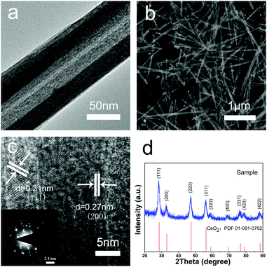
The morphologies and structures of the CeO2 nanotubes were investigated by SEM and TEM (Fig. 1a and b). It was found that the CeO2 samples are hollow tubular in shape with a narrow size distribution, and the average dimension of the CeO2 nanotubes is about 35 ± 5 nm in inner diameter, 70 ± 10 nm in outer diameter, and 2.5 ± 0.5 μm in length. As observed from the XRD analysis, all the diffraction peaks can be assigned to a cubic fluorite-type Fm3m crystal structure of CeO2 (a = 0.5411 nm, JCPDS No. 34-0394 or PDF card No. 01-081-0792) (Fig. 1d), with no other crystalline impurities being detected. Moreover, the high resolution TEM (HRTEM) images indicate that the shell of the tubes is about 15 nm in diameter, and two sets of atomic lattice fringes with the interplanar spacing of 0.27 nm and 0.31 nm correspond to the (200) and (111) crystal planes of the cubic CeO2, respectively (Fig. 1c). Note that the obtained material is highly crystalline, which exhibits a single crystal-like pattern with ordered bright matrix diffraction spots (inset in Fig. 1c). There are two sets of diffraction spots possibly because the electron beam penetrates the thin wall of the tube and projects on the other side of the wall, and the walls at the opposite sides have a small difference in crystal orientation. However, metal oxides with high crystallinity are ideal support materials for a catalytic reaction due to their excellent chemical stability, high-temperature resistivity, and good repeatability. Moreover, good crystallinity means fewer defects and traps for electron transfer, which is also favourable for the catalytic reaction.Note that this synthesis method is simple, effective, and controllable. Impressively, the product was obtained in high yield (about 80% of the product was in tubular morphology) and had good reproducibility. These advantages are critical for practical application of advanced materials.
3.2 Study of the CeO2 nanotube formation process
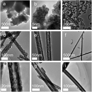
A complete understanding of the CeO2 nanotube formation and growth in solution is essential for the optimization of the synthesis method and provides guidance for the design and fabrication of CeO2 and other nanocrystals of well-defined morphologies. Therefore, the crystal growth mechanism of the CeO2 nanotube was elucidated according to the analysis of the crystal structures and morphologies obtained after reaction for different time periods.As shown in Fig. 2, the product at the initial stage of reaction demonstrates an amorphous state (Fig. 2a). Subsequently, the synthesized nanocrystals changed to the regular hexagon sheets with an average size of about 5 nm. HRTEM images show that most particles are uniform, with a (111) crystal face and a (100) crystal face exposed (Fig. 2b). The following growth process reveals severe agglomeration of the sheets. The most crystals appear to have the irregular stereo shapes, with an average size of around 10–20 nm. These particles tend to further agglomerate together. The TEM image shows that elongated nanocrystals originate from the fusion of some neighbouring nuclei via sharing of the common crystallographic orientation, resulting in the elongated or assembled structure (Fig. 2c). After this, the CeO2 nanorods with a rather rough surface were formed, and a close observation of these nanorods disclosed that they were assemblies and composed of small NPs29 (Fig. 2d). After this, the inner structure of the rods tended to be loosened (Fig. 2e), leading to the occurrence of some cavities with rapidly increasing diameter (Fig. 2f). Simultaneously, gain boundaries began to coalesce and disappear (Fig. 2h and g). Finally, nanotubes with uniform and smooth walls were formed (Fig. 2i). Note that the phase of the samples did not change with the prolongation of the reaction time (Fig. S1, ESI†). The samples that reacted in a very short time (about 5 min) already displayed highly crystalline structures, and the crystal pattern was retained regardless of the changes in the morphology and size.
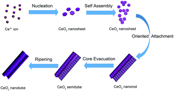
Unlike the most common nanotube synthesis via micelle templating of the self-assembled surfactant molecules, the product obtained herein exhibited a transformation from ceria nanoparticles to nanorods and finally to nanotubes. According to the study on the intermediate state of CeO2 nanotubes, we proposed an oriented attachment-Ostwald ripening mechanism (shown in Scheme 1). At the beginning, CeO2 nucleated, which involved precipitation of Ce3+ cations by OH− ions to form Ce(OH)328 and transition from Ce(OH)3 to CeO2 nuclei (hexagon sheets, 4–5 nm) through an oxidation and dehydration process. The oxidation and dehydration process rapidly and simultaneously occurred because no crystalline Ce(OH)3 or Ce(OH)4 phase was found in the product. After the initial formation of CeO2 nanosheets was finished, the oriented CeO2 attachment nanosheets were formed. Under the alkaline conditions (pH ≈ 9–10), the dehydration process occurred among hydroxyl groups on the surface of CeO2 to form Ce–O–Ce bonds, giving rise to aggregation between adjacent CeO2 nanosheets. As the CeO2 nanosheets possess both low energy facets (mainly (111)) and relatively higher energy facets (the edges of nanosheets, probably (100) and (110)),21 they tend to orientedly aggregate by sharing the high energy facets at the edges of the nanosheets through coalescing and fusion. Instead of separately growing larger laterally, the sheets cylindrically curved into a closed surface to reduce the energy of the system further (taking the kinetic speed factors into consideration as well). Then, the subsequent nanosheets tended to settle down on the established cylinder surface, and the radius dimension of the nanostructure gradually increased. Finally, the nanosheets stacked to form a 1D elongated nanorod morphology with the low energy facets exposed. The following stage of nanocrystal growth was dominated by the Ostwald ripening process. When the energetically unstable structure made of many small nanocrystals was formed, it tended to form a more energetically favoured regular well-defined larger crystalline structure at the expense of small crystallites to minimize the total surface area. Thus, the Ostwald ripening process occurred, and the cavity was generated in a location where crystallites were smaller and/or less compact.27 The smaller CeO2 grains dissolved and left cavities at the center of the rods. The cavity within the nanorods became bigger and bigger as the ripening process proceeded further. Finally, the dissolution and precipitation occurred and converted the oriented aggregated assemblies into regular crystalline nanotubes. In this specific case, we can observe that the rough rod-like aggregates consisting of small CeO2 nanocrystals finally turned into uniform single-crystalline-like nanotubes. Note that the surfactant P123 plays an important role in the hollow cavity formation process, and the control experiments indicate that there is barely any transformation from nanorods to nanotubes without the addition of P123 (Fig. S2, ESI†). We conjectured that the roles of P123 were as follows: (1) P123 hindered the growth and recrystallization of the inner crystallites via partially blocking the initial CeO2 nuclei to restrain small size or loose morphology; (2) P123 weakened the aggregation and oriented attachment of the nanosheets by capping the surfaces of the primary crystals, such that the fusion between adjacent crystals via elimination of surface hydroxyls and formation of the Ce–O–Ce bond was hindered as well. Apparently, an appropriate amount of P123 that could provide an ideal concentration gradient from the center to the outer part of the nanorods is the key factor for formation of highly qualified nanotubes.
3.3 Synthesis and characterization of the Au/CeO2 nanotubes
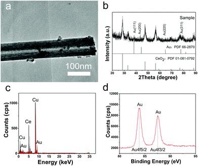
Different from previous reports, in this study, Au NPs could be formed on CeO2 nanotubes by simply adjusting pH of the reaction system without the addition of any other reductant. As shown in the TEM image (Fig. 3a), the Au NPs of less than 5 nm with darker contrast were deposited on the surface of the CeO2 nanotubes, and the composite can be confirmed by the EDS analysis. The XRD pattern further shows that the product is composed of fluorite-type CeO2, and some diffraction peaks of Au can be discerned although they are very weak, owing to the low loading amount and small particle size. Moreover, the XPS spectrum of Au 4f displays typical duplet peaks with the binding energy of 87.6 and 83.9 eV, revealing that Au existed in the elementary metallic form.22,24 Moreover, the O 1s XPS spectrum shows an apparent difference between CeO2 and Au/CeO2 nanotubes (Fig. S3, ESI†), which is another indication of the successful loading of Au NPs.With respect to the loading process of the Au NPs, we proposed that its reduction mechanism is as follows. Under aqueous conditions, chloroauric acid ionized into protons and chloroauric ions. Chloroauric ions are known to be extremely unstable and tend to decompose. At higher pH (about 10.0), the bound chlorine ions are partially released and replaced by the hydroxyl groups, and the reaction results in the formation of [Au(OH)xCl4−x]− anions.29 After the CeO2 nanotube slurry is added into the solution, many active sites are provided for the gold precursors. For instance, the surrounded hydroxyl groups on CeO2 would absorb Au3+ to form Ce–O–Au bonds. By maintaining the pH value of the system at 10, abundant OH− would act as reductant and donate the electrons to [Au(OH)xCl4−x]− anions, promoting the reduction of Au(III). In addition to the abovementioned favourable kinetic conditions, the semiconductor property of CeO2 may contribute to the thermodynamic driving force for Au NP formation.30
3.4 Catalytic test of Au/CeO2 nanotubes
To evaluate the performance of Au/CeO2 nanotubes for catalytic oxidation of CO, Au/CeO2 nanotubes with different Au loading amounts and different particle sizes were investigated along with a contrast sample of bare CeO2 nanotubes. Fig. 4 summarizes the typical conversion ratio of CO as a function of reaction temperature over five catalysts under the same conditions. It can be seen that the Au/CeO2 samples are already active at room temperature and the CO conversion ratio is about 20%. By comparison, pure CeO2 nanotubes only show activity above 200 °C. With the increasing reaction temperature, the complete CO conversion for the Au/CeO2 sample was achieved at about 73 °C. As for the CO oxidation over pure CeO2, a temperature of 338 °C was needed to reach a conversion ratio of 100%. Note that to date, only slight improvement in the catalytic activity over other CeO2-based materials has been reported in the literature.31 Evidently, the presence of Au NPs, regardless of the fact that whether they are inside or outside the CeO2 tubes, could efficiently enhance the catalytic activity of CeO2, demonstrating the synergetic effect of Au and CeO2 during the catalytic processes. On the one hand, when Au was present, more oxygen vacancies formed and the oxygen species nearby were activated.32 On the other hand, CeO2 contributed to the dispersion and anchoring of Au nanoparticles, prevented them from sintering together and maintained the high activity during the catalytic reaction process.33 Thus, the catalytic performance showed strong mutual reinforcement.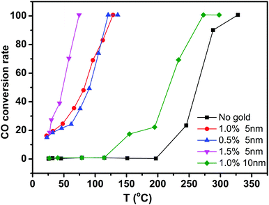 | ||
| Fig. 4 Catalytic activities of CeO2 nanotubes with different gold loading amount and different particle sizes. | ||
Moreover, we compared the catalytic activity of the Au/CeO2 nanotubes with different Au loading contents. As shown in Fig. 4, the order of catalytic activity was obtained as follows: 1.5% Au/CeO2 > 1% Au/CeO2 > 0.5% Au/CeO2 ≫ CeO2. The difference in the catalytic activity mainly originates from different active sites in the samples. The sizes of Au NPs in all the samples were around 3–5 nm (Fig. 3a and Fig. S4a, ESI†), and the increase of Au content was favourable for the improvement of the catalytic activity. This is because the Au species, which activated and enriched the CO and O2 molecules and greatly decreased the absorption energy of both reactants, were the active sites for CO oxidation in Au/CeO2 systems. Increase in the number of active sites with the increasing Au content was favorable for catalysis. The investigation on Au particle size demonstrates that the sample of 1% Au/CeO2 with the Au NP sizes of about 5 nm (Fig. S4b, ESI†) possesses much higher catalytic activity than that with Au NPs of 10 nm diameter. We attributed this to the increase of low coordination Au sites and the stronger interaction between the Au NPs and supports for smaller Au NPs compared with those for larger Au NPs.
Stability is another important index to assess the performance of the catalysts. We set the temperature of the catalytic reaction at 100 °C, at which the CO conversion ratio was 100%. As displayed in Fig. S5 (ESI†), no deactivation occurred even when the catalytic reaction was performed for as long as 100 h. The XPS spectrum further reveals that there are no obvious changes in the chemical state of the active sites (Fig. S6, ESI†) after the catalytic reaction. Evidently, encapsulation of Au NPs inside the CeO2 matrix or the strong attachment of Au NPs on the CeO2 surface can effectively improve their stability during the catalytic process.
4. Conclusions
In summary, by developing a precisely controlled surfactant-assisted solvothermal method, CeO2 nanotubes with high quality and yield were constructed. Compared with the previously reported results, the CeO2 nanotubes could be obtained in much higher yield, better uniformity, and higher crystallinity. Detailed analysis of the synthetic procedure discloses that the formation of the CeO2 nanotubes follows the oriented attachment-Ostwald ripening mechanism. After the loading of Au NPs, the Au/CeO2 nanotubes show excellent performance in the CO oxidation reaction with the full CO conversion temperature as low as 73 °C. Furthermore, these Au/CeO2 nanotubes exhibit a high stability, and no deactivation happens after 100 h of reaction. This solvothermal strategy is expected to open the avenue towards the synthesis of nanomaterials with different morphologies as well as rational design and fabrication of the structure-controlled catalysts.Acknowledgements
We are grateful for the financial support received from the National Natural Science Foundation of China (No. 21271021, 51472025, 51572261) and Youth Innovation Promotion Association of CAS (No. 2017070).Notes and references
- M. Haruta, N. Yamada, T. Kobayashi and S. Iijima, J. Catal., 1989, 115, 301–309 CrossRef CAS.
- G. X. Chen, Y. Zhao, G. Fu, P. N. Duchesne, L. Gu, Y. P. Zheng, X. F. Weng, M. S. Chen, P. Zhang, C. W. Pao, J. F. Lee and N. F. Zheng, Science, 2014, 344, 495–499 CrossRef CAS PubMed.
- H. Y. Kim and G. Henkelman, J. Phys. Chem. Lett., 2012, 4, 216–221 CrossRef PubMed.
- H. J. Freund, G. Meijer, M. Scheffler, R. Schlogl and M. Wolf, Angew. Chem., Int. Ed., 2011, 50, 10064–10094 CrossRef CAS PubMed.
- W. L. Deng and M. Flytzani-Stephanopoulos, Angew. Chem., Int. Ed., 2006, 45, 2285–2289 CrossRef CAS PubMed.
- J. Li, Z. Zhang, W. Gao, S. Zhang, Y. Ma and Y. Qu, ACS Appl. Mater. Interfaces, 2016, 8, 22988–22996 CAS.
- C. W. Sun, H. Li and L. Q. Chen, Energy Environ. Sci., 2012, 5, 8475–8505 CAS.
- S. Zhang, C. R. Chang, Z. Q. Huang, J. Li, Z. Wu, Y. Ma, Z. Zhang, Y. Wang and Y. Qu, J. Am. Chem. Soc., 2016, 138, 2629–2637 CrossRef CAS PubMed.
- Y. Liu, H. Li, J. Yu, D. Mao and G. Lu, Phys. Chem. Chem. Phys., 2015, 17, 27758–27768 RSC.
- M. M. Branda, C. Loschen, K. M. Neyman and F. Illas, J. Phys. Chem. C, 2008, 112, 17643–17651 CAS.
- W. X. Huang, Top. Catal., 2013, 56, 1363–1376 CrossRef CAS.
- L. S. Zhong, J. S. Hu, A. M. Cao, Q. Liu, W. G. Song and L. J. Wan, Chem. Mater., 2007, 19, 1648–1655 CrossRef CAS.
- J. Qi, K. Zhao, G. Li, Y. Gao, H. Zhao, R. Yu and Z. Tang, Nanoscale, 2014, 6, 4072–4077 RSC.
- L. Yan, X. R. Xing, R. B. Yu, J. X. Deng, J. Chen and G. R. Liu, Phys. B, 2007, 390, 59–64 CrossRef CAS.
- P. Xu, R. Yu, C. Wang, X. Yan, D. Wang, J. Deng, J. Chen and X. Xing, J. Nanosci. Nanotechnol., 2013, 13, 1498–1502 CrossRef CAS PubMed.
- L. Yan, X. R. Xing, R. B. Yu, L. J. Qiao, J. Chen, J. X. Deng and G. R. Liu, Scr. Mater., 2007, 56, 301–304 CrossRef CAS.
- L. Yan, R. Yu, J. Chen and X. Xing, Cryst. Growth Des., 2008, 8, 1474–1477 CAS.
- R. Yu, L. Yan, P. Zheng, J. Chen and X. R. Xing, J. Phys. Chem. C, 2008, 112, 19896–19900 CAS.
- X. Yao, X. Yang, R. Yu, P. Xu, J. Chen and X. Xing, Mater. Res. Bull., 2015, 61, 22–25 CrossRef CAS.
- K. Zhao, J. Qi, S. Zhao, H. Tang, H. Yin, L. Zong, L. Chang, Y. Gao, R. Yu and Z. Tang, Chin. J. Catal., 2015, 36, 261–267 CrossRef CAS.
- J. Qi, X. Y. Lai, J. Y. Wang, H. J. Tang, H. Ren, Y. Yang, Q. Jin, L. J. Zhang, R. B. Yu, G. H. Ma, Z. G. Su, H. J. Zhao and D. Wang, Chem. Soc. Rev., 2015, 44, 6749–6773 RSC.
- X. Y. Lai, J. E. Halperta and D. Wang, Energy Environ. Sci., 2012, 5, 5604–5618 CAS.
- K. Yoon, Y. Yang, P. Lu, D. H. Wan, H. C. Peng, K. S. Masias, P. T. Fanson, C. T. Campbell and Y. N. Xia, Angew. Chem., Int. Ed., 2012, 51, 9543–9546 CrossRef CAS PubMed.
- Z. Tang, X. Yin, Y. Zhang, N. Zhang and Y. Xu, Chin. J. Catal., 2013, 34, 1123–1127 CrossRef CAS.
- W. Q. Han, L. J. Wu and Y. M. Zhu, J. Am. Chem. Soc., 2005, 127, 12814–12815 CrossRef CAS PubMed.
- S. Carrettin, P. Concepción, A. Corma, J. M. López Nieto and V. F. Puntes, Angew. Chem., Int. Ed., 2004, 43, 2538–2540 CrossRef CAS PubMed.
- H. C. Zeng, Curr. Nanosci., 2007, 3, 177–181 CrossRef CAS.
- M. Lin, Z. Y. Fu, H. R. Tan, J. P. Y. Tan, S. C. Ng and E. Teo, Cryst. Growth Des., 2012, 12, 3296–3303 CAS.
- S. Wang, K. Qian, X. Z. Bi and W. X. Huang, J. Phys. Chem. C, 2009, 113, 6505–6510 CAS.
- B. Schumacher, V. Plzak, M. Kinne and R. J. Behm, Catal. Lett., 2003, 89, 109–114 CrossRef CAS.
- J. Qi, J. Chen, G. Li, S. Li, Y. Gao and Z. Tang, Energy Environ. Sci., 2012, 5, 8937–8941 CAS.
- V. Shapovalov and H. Metiu, J. Catal., 2007, 245, 205–214 CrossRef CAS.
- J. Shi, Chem. Rev., 2012, 113, 2139–2181 CrossRef PubMed.
Footnotes |
| † Electronic supplementary information (ESI) available: Fig. S1–S6. See DOI: 10.1039/c7qm00134g |
| ‡ These authors contributed equally to this work. |
| This journal is © the Partner Organisations 2017 |

