DOI:
10.1039/C6QM00248J
(Chemistry Frontiers)
Mater. Chem. Front., 2017,
1, 802-806
Low-temperature aqueous solution processed ZnO as an electron transporting layer for efficient perovskite solar cells†
Received
30th September 2016
, Accepted 29th November 2016
First published on 23rd December 2016
Abstract
Lead halide perovskite solar cells (PSCs) typically use high-temperature processed TiO2 as electron transporting layers (ETLs). Here, we report a low temperature and aqueous solution processed route to prepare ZnO ETLs for perovskite solar cells. The ZnO ETL was prepared by spin coating a stable aqueous solution of an ammine–hydroxo zinc complex, [Zn(NH3)x](OH)2, followed by thermal annealing at a relatively low temperature of 150 °C. The as-prepared ZnO film was highly transparent and uniform. Moreover, the relatively low work function of the ZnO film led to a high open circuit voltage (1.07 V), indicating its promise as the electron transporting layer. To further improve the photovoltaic performance, urea was introduced between the ZnO layer and the perovskite layer to improve the perovskite crystal growth. As a result, the PCE surged to 14.6%. We further exploited the low-temperature processed ZnO film for flexible PSCs, which have shown good mechanical stability with a respectable PCE of 11.9%.
Introduction
Organic–inorganic lead halide perovskite solar cells (PSCs) have drawn broad attention in recent years.1–8 The power conversion efficiency of PSCs has reached over 22%,9,10 which is largely attributed to the superior photovoltaic properties of lead halide perovskites, such as a broad absorption band with a high extinction coefficient,11 high electron and hole mobility,12 and long electron–hole diffusion length.13 Highly efficient PSCs mainly use TiO2 as the electron transporting layer (ETL). Typically, the TiO2 layer is prepared by spin-coating or spray pyrolysis of a solution of a TiO2 precursor followed by annealing at 500 °C in order to transform the amorphous oxide layer into the crystalline form, which prevents the use of flexible plastic substrates as they are unstable at high temperature. Hence, a low-temperature processed ETL material should be explored.14,15 Among the ETL materials, ZnO is the most promising owing to its high transparency, low work function and high electron mobility.16–18 A number of techniques, such as electro-deposition, sol–gel and solution-processing of nanoparticles, were demonstrated to prepare ZnO ETLs for perovskite solar cells. The electro-deposition method is complex,19 and the solution method is attractive in order to take advantage of the high throughput fabrication techniques. The most widely used solution processed ZnO sol–gel method20 requires thermal annealing at a high temperature, typically above 200 °C, due to the high decomposition temperature of the precursor (zinc acetate), which prevents the fabrication of flexible solar cells. For flexible solar cells, a lower processing temperature is always preferred. Recently, Liu et al.21 reported that perovskite solar cells using low-temperature solution-processed ZnO colloidal nanoparticles as the ETL material could achieve a high power conversion efficiency (PCE) of 15.7%. But the stock solution containing ZnO colloidal nanoparticles was not stable due to the aggregation of the nanoparticles in solution.
In this study, we demonstrated a low temperature and solution processed route, based on an ammine–hydroxo zinc complex solution instead of the ZnO nanoparticle suspension, to prepare the ZnO ETLs for perovskite solar cells at a relatively low temperature of 150 °C, which exhibited a PCE of 10.6% with a high open circuit voltage of 1.07 V. To further improve the photovoltaic performance, urea was introduced between the ZnO layer and the perovskite layer to tune the perovskite crystal growth. The PCE surged to 14.6% with the modification of urea on ZnO, which is one of the highest values obtained for ZnO based planar n–i–p PSCs. Moreover, using the prepared ZnO as ETLs, efficient flexible PSCs with good mechanical stability can also be achieved. The PCE can reach a promising value of 11.9% for flexible PSCs. This renders the prepared ZnO a promising ETL for highly efficient PSCs.
Results and discussion
Aqueous solution processed ZnO film
The aqueous [Zn(NH3)x](OH)2 solution was prepared according to previous report.22 The Zn(OH)2 precipitate was firstly produced by the reaction of Zn(NO3)2 and NaOH. Then, the precipitate was suspended in water, followed by centrifugation and supernatant removal. Rinse and separation steps were repeated three times to remove Na+ and NO3−. After the final centrifugation, the Zn(OH)2 precipitate was dissolved in aqueous ammonia to form a stock solution. The Zn concentration in the stock solution was about 0.12 M. The stock solution was stable under ambient conditions for over three months. The ZnO thin films were prepared by spin coating the aqueous solution onto the substrates, followed by annealing at 150 °C for 10 min. Precipitation, dissolution, and ammonia dissociation schemes are expressed as
| Zn(NO3)2(aq) + 2NaOH(aq) → Zn(OH)2(s) + 2NaNO3(aq) |
| Zn(OH)2(s) + xNH3(aq) → [Zn(NH3)x](OH)2(aq) |
| [Zn(NH3)x](OH)2(aq) → ZnO(s) + xNH3(g) + H2O(g) |
Physical properties of the ZnO film
Fig. 1a shows the optical transmittance spectra of the ZnO film. The prepared ZnO demonstrates a slightly higher transmittance compared to the ITO substrate in the visible region. Fig. 1b shows scanning electron microscopy (SEM) images of the ZnO film. The ZnO film appears dense and continuous. These results reveal that the low-temperature, aqueous solution processed ZnO film is highly transparent and uniform, which is an ideal ETL material for perovskite solar cells.
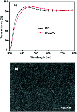 |
| | Fig. 1 (a) Transmission spectra and (b) SEM image of the as-prepared ZnO films. | |
For the ETL material, a lower work function is desirable for the reduction in a charge extraction barrier. According to the UPS measurements (Fig. 2), the work function of the ZnO film prepared in this report is determined to be 3.71 eV, which is lower than the work function of the ZnO film prepared using the widely used sol–gel method (4.15 eV).20 The lower work function of the prepared ZnO film improves the energy level alignment between ZnO and perovskite, which increases the carrier extraction and charge generation. Moreover, the lower cathode work function provides a larger built-in potential to facilitate the charge transport. These effects would increase Voc of PSCs.
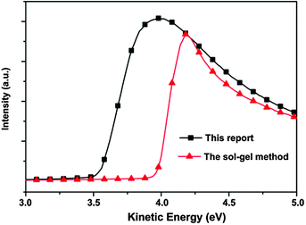 |
| | Fig. 2 UPS spectra of the ZnO films prepared using the aqueous solution method (this report) and the sol–gel method. | |
Device performance of ZnO based PSCs
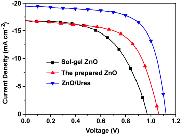
We fabricated PSCs using the prepared ZnO film as ETL based on the planar n–i–p device structure of glass/ITO/ZnO/ CH3NH3PbI3/spiro-OMeTAD/Ag. As shown in Fig. 3 and Table 1, the PSC with the prepared ZnO as ETL showed the best PCE of 10.6% with the high open circuit voltage (Voc) of 1.07 V, which is higher than the Voc of the sol–gel ZnO based PSCs (0.97 V). The higher Voc should be ascribed to the lower work function of the prepared ZnO, indicating that the prepared ZnO film is an excellent ETL material for high performance PSCs. To further improve the photovoltaic performance, urea was introduced between the prepared ZnO film and perovskite to tune the perovskite crystal growth. The device based on the planar n–i–p device structure of glass/ITO/ZnO/urea/ CH3NH3PbI3/spiro-OMeTAD/Ag was fabricated. After the modification of urea on ZnO, the PCE surged to 14.6%. For the CH3NH3PbI3 perovskite film, the substrates covered with an amino group would favor the growth of smooth and high crystalline perovskite films. The introduction of urea with two amino groups resulted in about 38% enhancement of PCE and the simultaneous improvement of all the device parameters. We attributed the improved device performance to the evolved morphology of CH3NH3PbI3 film on the urea surface. It should be noted that the hysteresis was observed for the PSC device (Fig. S5, ESI†), which is always shown in the PSCs with the planar n–i–p structure.
 |
| | Fig. 3
J–V curves of the perovskite CH3NH3PbI3-based solar cells using the ZnO ETL with the reverse scan. | |
Table 1 Device parameters of the PSCs with the reverse scan
| |
V
oc [V] |
J
sc [mA cm−2] |
FF [%] |
PCE [%] |
| Best |
Average |
| Sol–gel ZnO |
0.97 |
16.79 |
57 |
9.3 |
8.5 |
| Bare ZnO |
1.07 |
16.81 |
59 |
10.6 |
9.1 |
| ZnO/urea |
1.12 |
19.94 |
66 |
14.6 |
13.4 |
Urea modification
To investigate the effects of urea on the morphology of CH3NH3PbI3 perovskite film, Fig. 4 shows the scanning electron microscopy (SEM) images of perovskite film surface morphology on different substrates. The SEM images of the CH3NH3PbI3 film directly showed that the number of pin-holes was reduced with the deposition of urea on the ZnO. The amino groups of urea would act as the nucleation center for CH3NH3PbI3 deposition and crystal growth. The well-covered perovskite on the ZnO/urea substrate can be observed in Fig. 4b. In contrast, the CH3NH3PbI3 perovskite crystals show many pin-holes on the top of bare ZnO in Fig. 4a, which would lead to current leakage.
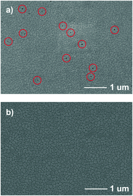 |
| | Fig. 4 SEM images of CH3NH3PbI3 formed on (a) bare ZnO and (b) ZnO/urea (pin-holes are in red circles). | |
In order to further look into the influence of urea modification on the improvement of photovoltaic performance, we investigated charge dynamics by measuring photoluminescence (PL) and time-resolved photoluminescence (TRPL) of the perovskite film on bare ZnO and ZnO/urea. Fig. 5a shows the steady-state PL spectra of perovskite films on bare ZnO and ZnO/urea, which were excited at 450 nm. The PL intensity of the ZnO/urea/perovskite film was reduced compared with that of ZnO/perovskite film, while the absorbance of the two films is essentially the same. This result shows fast electron injection from perovskite into ZnO after the modification of urea. Furthermore, the TRPL was measured by monitoring the peak emission at 768 nm as shown in Fig. 5b. Fitting the data with tri-exponential decay yields three time constants, i.e. τ1, τ2 and τ3, as summarized in Table S1 (ESI†). The decay component of τ1 ∼ 9 ns might come from the bulk recombination in the perovskite bulk film, and the decay component of τ2 ∼ 100 ns could be attributed to the recombination of free carriers in the radiative channel. For ZnO/perovskite, τ1 is 9.6 ns with a 9.25% ratio and τ2 is 142.2 ns with an 80.83% ratio. As for ZnO/urea/perovskite, both τ1 and τ2 were shortened to 8.8 ns and 84.7 ns, respectively. The faster charge transfer rate indicated stronger electronic coupling between the ZnO and CH3NH3PbI3 perovskites with the modification of urea. This is consistent with enhanced Jsc and FF from the urea modified ZnO-based device.
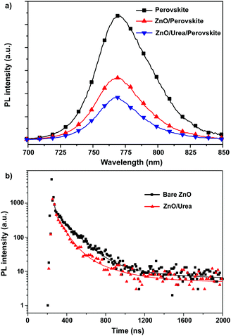 |
| | Fig. 5 (a) The steady-state PL spectra of perovskite film on glass, bare ZnO and ZnO/urea. (b) TRPL decay transient spectra of ITO/ZnO/perovskite and ITO/ZnO/urea/perovskite. | |
Flexible perovskite solar cells
We replaced the rigid glass/ITO substrate with a flexible PET/ITO substrate and fabricated the solar cell devices using the same procedures. Flexible perovskite solar cells based on the structure of PET/ITO/ZnO/urea/perovskite/spiro-OMeTAD/Ag were fabricated. Fig. 6a shows the photocurrent density–voltage (J–V) curve of the ZnO-based flexible PSC. The J–V curve exhibits a short circuit current density (Jsc) of 18.7 mA cm−2, an open circuit voltage (Voc) of 1.12 V, and fill factor (FF) of 0.57, resulting in PCE of 11.9%. In addition, we performed mechanical bending tests over 500 cycles. As shown in Fig. 6b, the performance of the device retains over 80% of its initial efficiency even after 500 bending cycles.
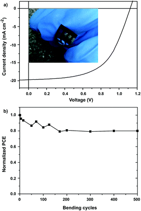 |
| | Fig. 6 (a) J–V curves for the best flexible PSC and the photograph of the ZnO-based flexible PSC (inset). (b) Normalized PCE of ZnO-based flexible PSCs as a function of bending cycles. | |
Conclusions
We reported a low temperature and solution processed route to prepare the ZnO ETLs for perovskite solar cells by spin coating the aqueous solutions of an ammine–hydroxo zinc complex, [Zn(NH3)x](OH)2, followed by thermal annealing at a relatively low temperature of 150 °C. The prepared ZnO shows high transparency and a low work function. Perovskite solar cells with the prepared ZnO as ETLs exhibited a PCE of 10.6% with a high open circuit voltage of 1.07 V. To further improve the photovoltaic performance, urea was introduced between the ZnO layer and the perovskite layer to tune the perovskite crystal growth. The PCE surged to 14.6% with the modification of urea on ZnO. The deposition of urea resulted in the improved morphology of the crystalline perovskite film without pin-holes and the enhanced electronic coupling between the ZnO layer and the perovskite layer. Moreover, using the prepared ZnO as ETLs, efficient flexible PSCs with good mechanical stability can also be achieved. The PCE can reach a promising value of 11.9% for flexible PSCs. These results define a promising approach to the fabrication of a high efficient electron transporting layer of the perovskite solar cell at low temperature.
Acknowledgements
This work was supported by the Natural Science Foundation of China (21503011), the Fundamental Research Funds for the Central Universities (buctrc201516), RGC of Hong Kong (GRF No. 16300915) and HK Innovation and Technology Fund (ITS/004/14).
Notes and references
- A. Kojima, K. Teshima, Y. Shirai and T. Miyasaka, J. Am. Chem. Soc., 2009, 131(17), 6050–6051 CrossRef CAS PubMed.
- J.-H. Im, C.-R. Lee, J.-W. Lee, S.-W. Park and N.-G. Park, Nanoscale, 2011, 3(10), 4088–4093 RSC.
- H.-S. Kim, C.-R. Lee, J.-H. Im, K.-B. Lee, T. Moehl, A. Marchioro, S.-J. Moon, R. Humphry-Baker, J.-H. Yum, J. E. Moser, M. Grätzel and N.-G. Park, Sci. Rep., 2012, 2, 591 Search PubMed.
- M. M. Lee, J. Teuscher, T. Miyasaka, T. N. Murakami and H. J. Snaith, Science, 2012, 338(6107), 643–647 CrossRef CAS PubMed.
- J. Burschka, N. Pellet, S.-J. Moon, R. Humphry-Baker, P. Gao, M. K. Nazeeruddin and M. Gratzel, Nature, 2013, 499(7458), 316–319 CrossRef CAS PubMed.
- M. Liu, M. B. Johnston and H. J. Snaith, Nature, 2013, 501(7467), 395–398 CrossRef CAS PubMed.
- J.-H. Im, I.-H. Jang, N. Pellet, M. Grätzel and N.-G. Park, Nat. Nanotechnol., 2014, 9(11), 927–932 CrossRef CAS PubMed.
- H. Zhou, Q. Chen, G. Li, S. Luo, T.-B. Song, H.-S. Duan, Z. Hong, J. You, Y. Liu and Y. Yang, Science, 2014, 345(6196), 542–546 CrossRef CAS PubMed.
- N. J. Jeon, J. H. Noh, W. S. Yang, Y. C. Kim, S. Ryu, J. Seo and S. I. Seok, Nature, 2015, 517(7535), 476–480 CrossRef CAS PubMed.
- W. S. Yang, J. H. Noh, N. J. Jeon, Y. C. Kim, S. Ryu, J. Seo and S. I. Seok, Science, 2015, 348, 1234 CrossRef CAS PubMed.
- Y. Zhao and K. Zhu, J. Am. Chem. Soc., 2014, 136(35), 12241–12244 CrossRef CAS PubMed.
- C. Wehrenfennig, G. E. Eperon, M. B. Johnston, H. J. Snaith and L. M. Herz, Adv. Mater., 2014, 26(10), 1584–1589 CrossRef CAS PubMed.
- A. Abrusci, S. D. Stranks, P. Docampo, H.-L. Yip, A. K. Y. Jen and H. J. Snaith, Nano Lett., 2013, 13(7), 3124–3128 CrossRef CAS PubMed.
- S. S. Shin, W. S. Yang, J. H. Noh, J. H. Suk, N. J. Jeon, J. H. Park, J. S. Kim, W. M. Seong and S. I. Seok, Nat. Commun., 2015, 6, 7410 CrossRef CAS PubMed.
- W. Ke, G. Fang, Q. Liu, L. Xiong, P. Qin, H. Tao, J. Wang, H. Lei, B. Li, J. Wan, G. Yang and Y. Yan, J. Am. Chem. Soc., 2015, 137(21), 6730–6733 CrossRef CAS PubMed.
- X. Xu, H. Zhang, J. Shi, J. Dong, Y. Luo, D. Li and Q. Meng, J. Mater. Chem. A, 2015, 3(38), 19288–19293 CAS.
- J. Kim, G. Kim, T. K. Kim, S. Kwon, H. Back, J. Lee, S. H. Lee, H. Kang and K. Lee, J. Mater. Chem. A, 2014, 2(41), 17291–17296 CAS.
- C. Huang, W. Fu, C.-Z. Li, Z. Zhang, W. Qiu, M. Shi, P. Heremans, A. K. Y. Jen and H. Chen, J. Am. Chem. Soc., 2016, 138(8), 2528–2531 CrossRef CAS PubMed.
- M. H. Kumar, N. Yantara, S. Dharani, M. Graetzel, S. Mhaisalkar, P. P. Boix and N. Mathews, Chem. Commun., 2013, 49(94), 11089–11091 RSC.
- L. Zuo, Z. Gu, T. Ye, W. Fu, G. Wu, H. Li and H. Chen, J. Am. Chem. Soc., 2015, 137(7), 2674–2679 CrossRef CAS PubMed.
- D. Liu and T. L. Kelly, Nat. Photonics, 2014, 8(2), 133–138 CrossRef CAS.
- S. T. Meyers, J. T. Anderson, C. M. Hung, J. Thompson, J. F. Wager and D. A. Keszler, J. Am. Chem. Soc., 2008, 130(51), 17603–17609 CrossRef CAS PubMed.
Footnote |
| † Electronic supplementary information (ESI) available: Synthesis of ZnO precursor, fabrication and characterization of PSCs, XRD of the perovskite film, EQE spectra of the perovskite CH3NH3PbI3-based solar cell using the ZnO ETL, histograms of PCEs measured for 30 cells using the ZnO ETLs with or without urea modification, the contact angle of water of the ZnO films with or without urea modification. See DOI: 10.1039/c6qm00248j |
|
| This journal is © the Partner Organisations 2017 |
Click here to see how this site uses Cookies. View our privacy policy here. 


